…or the chaos is overwhelming
<intro>
This time I present to you the fourth part of the epic Tesseract project. Links to the previous three posts are below:
Now, let’s get back to work :>

Buddha flash card
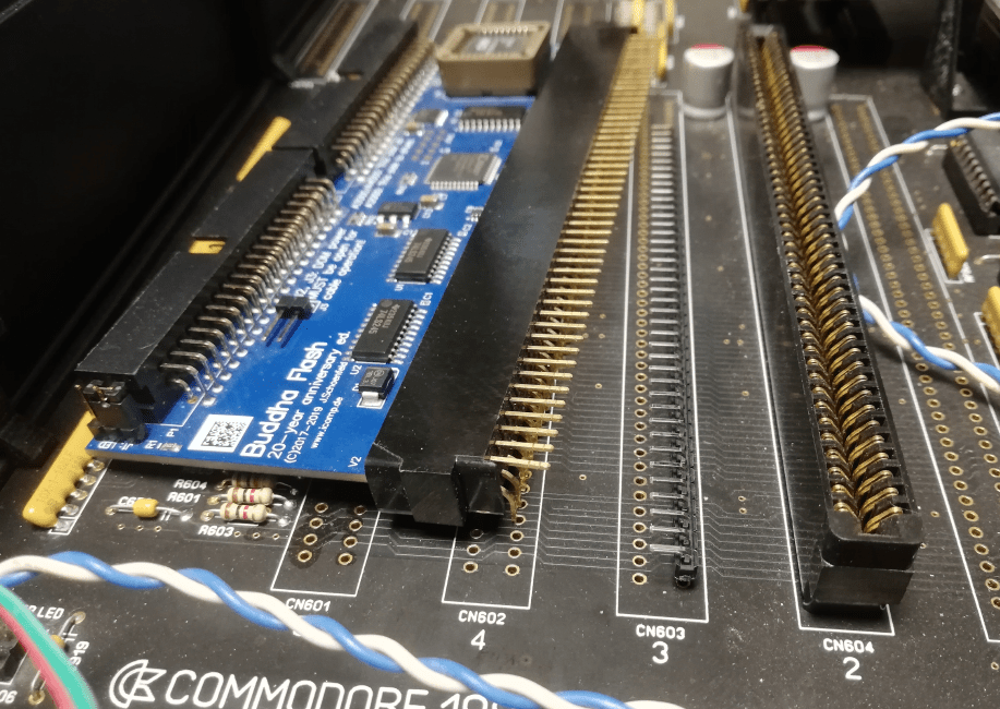
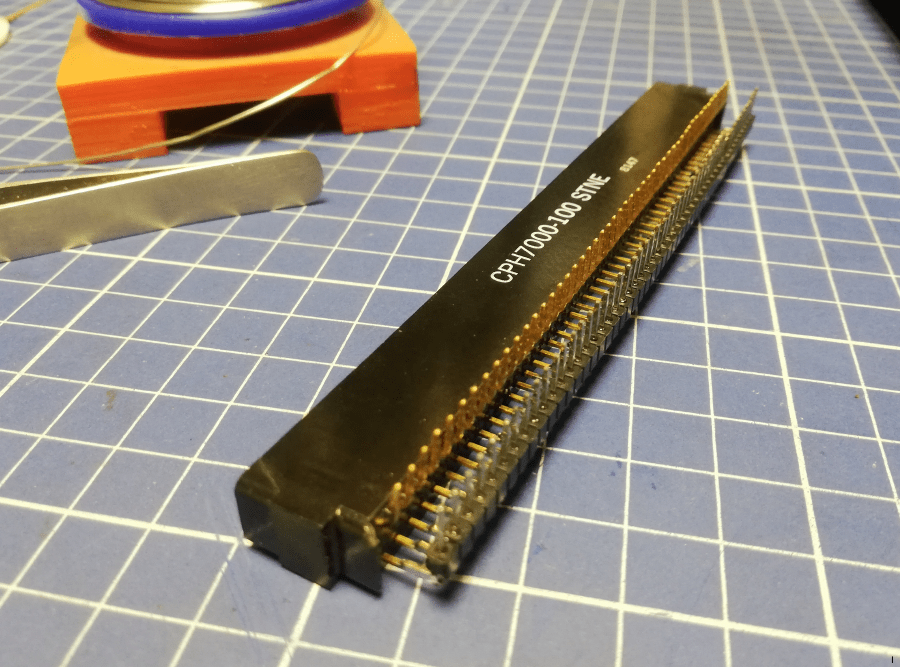
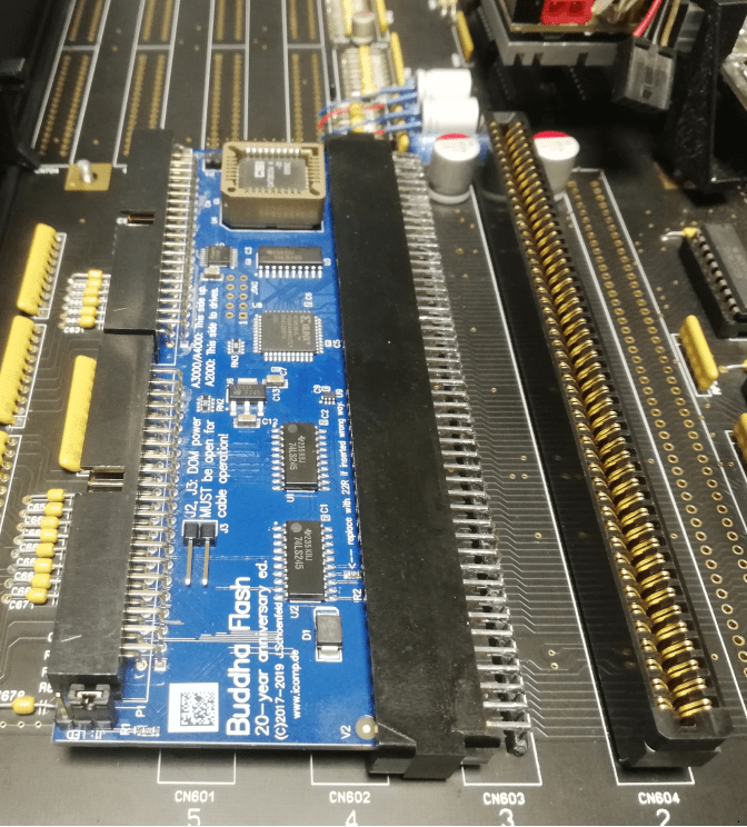
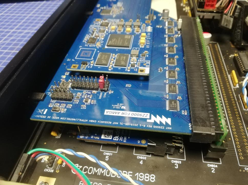
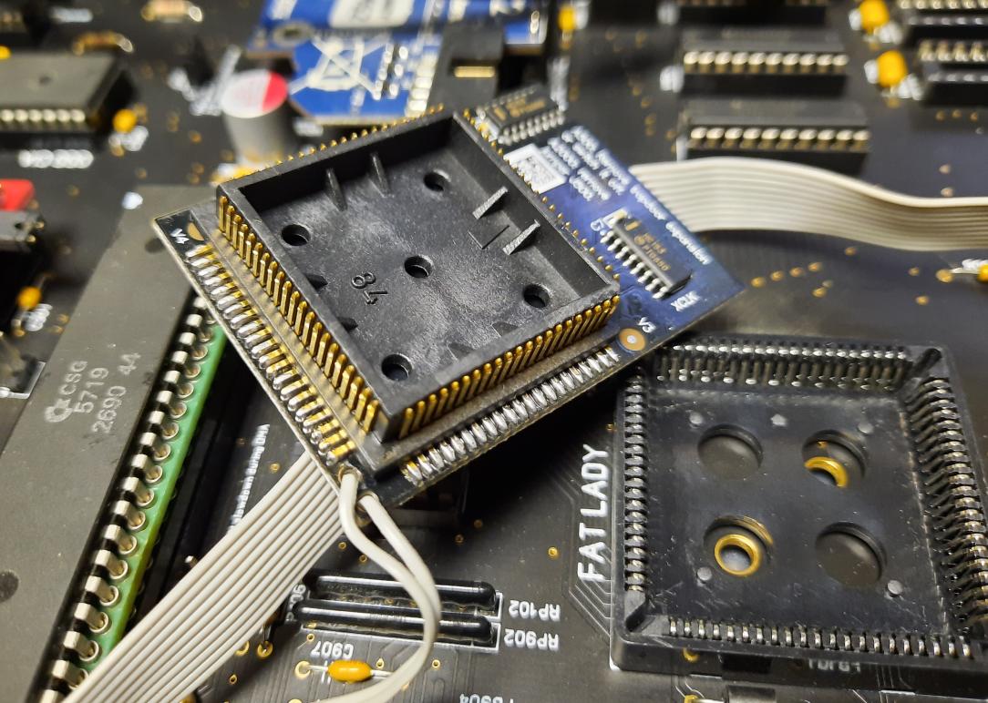
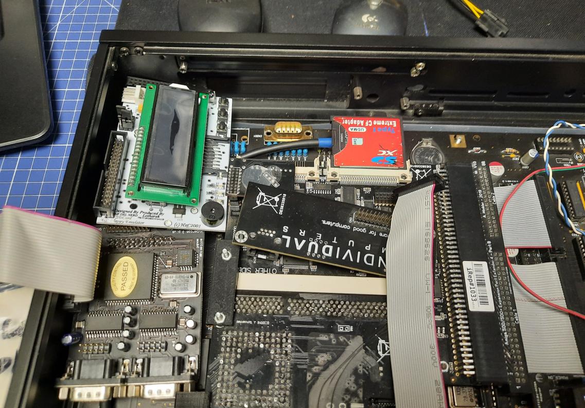
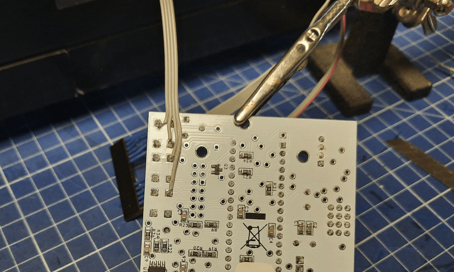
This is the third try to install a Buddha flash card. This time it is the Buddha Flash 20th anniversary edition and this one turned out to be perfect for this project. However, this time I didn’t even try to solder it directly. Instead, I’ve figured out a way to install it parallel to the mobo and still make it fit under ZZ9000. It required a bit of tinkering with a zorro socket.
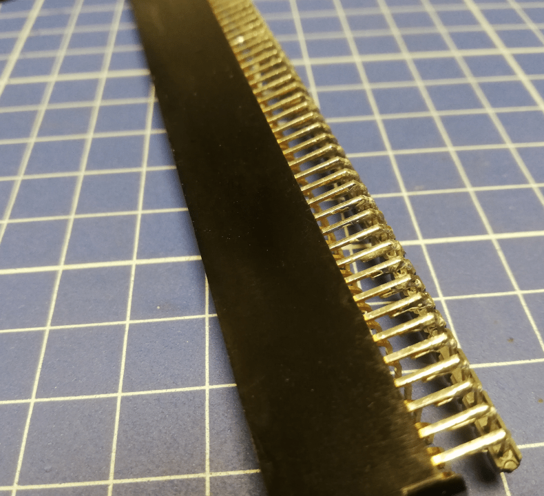
This is how it was done.
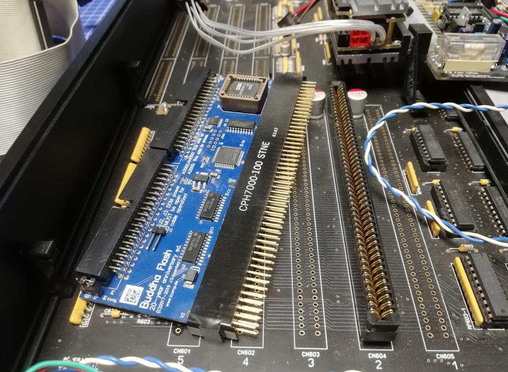
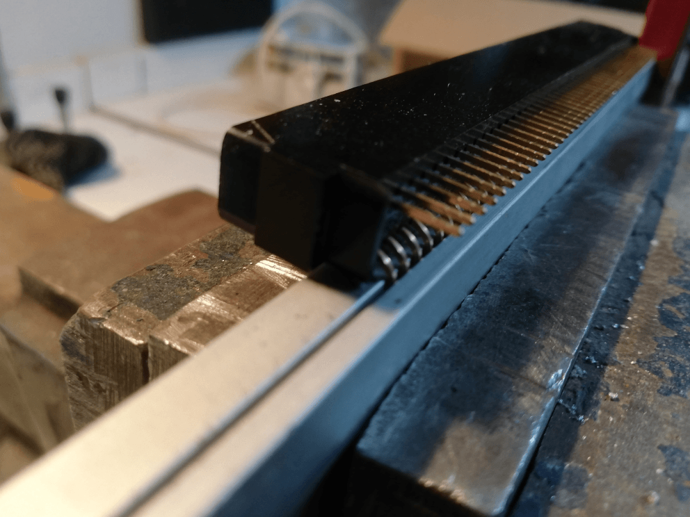
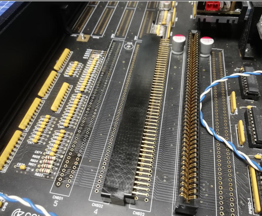
With the first row sorted, I had to find a solution to connect a second row. I installed a curved, single row of gold pins and soldered it to socket pins one by one.
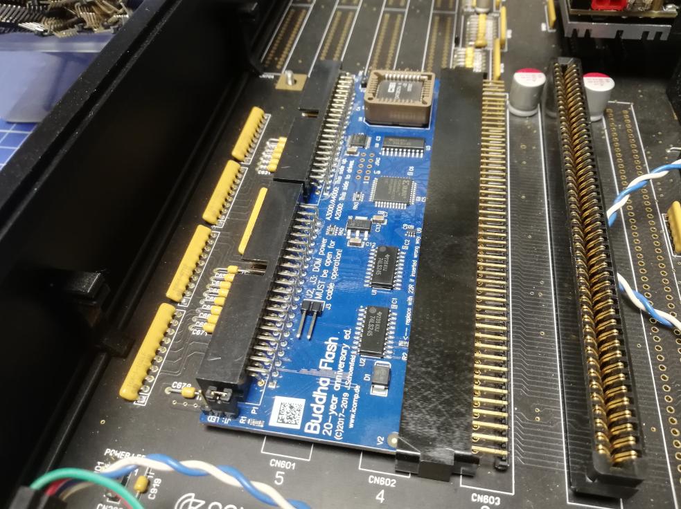
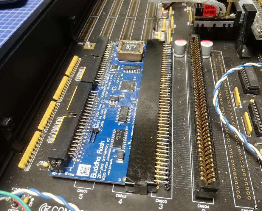
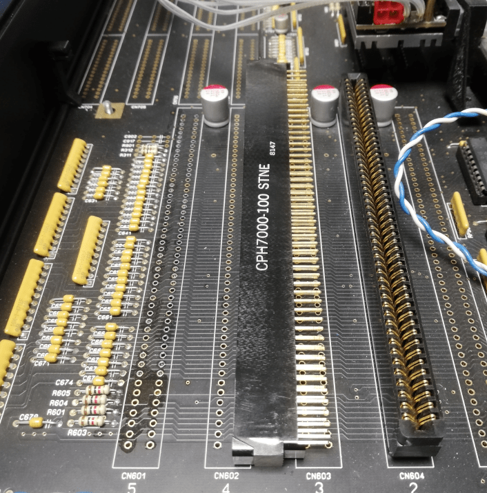
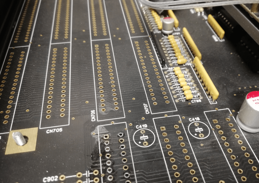
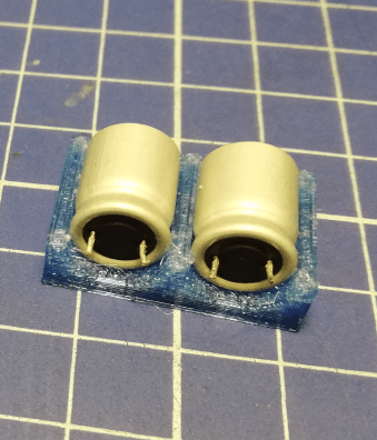
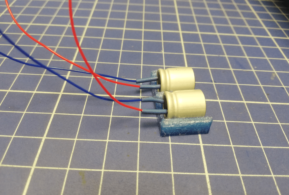
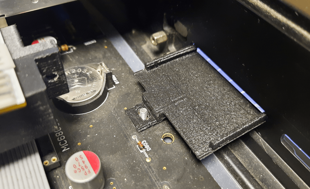
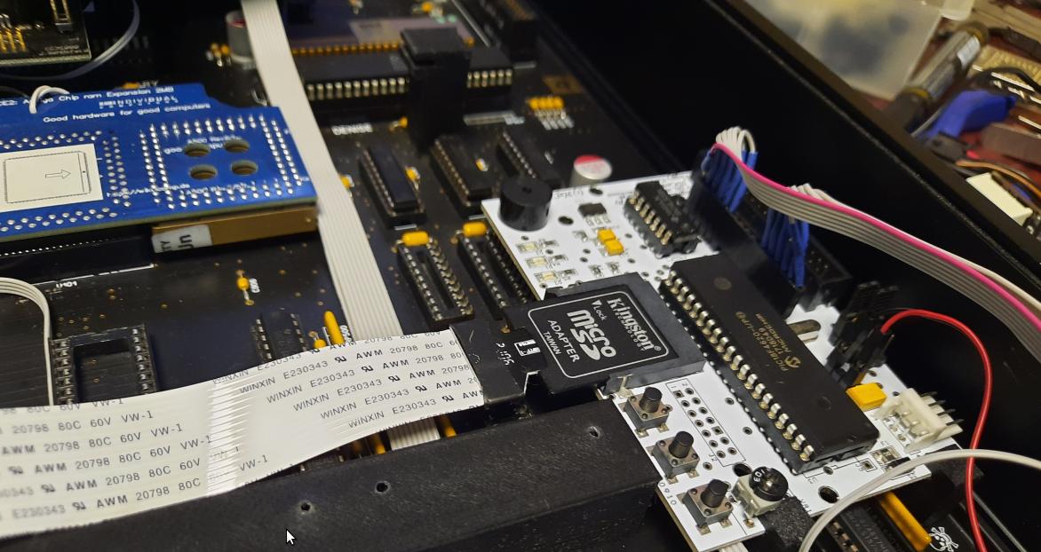
However, I had to remove two caps that collided with the card and find a new place for them. I did that by designing and 3D printing a smallholder.
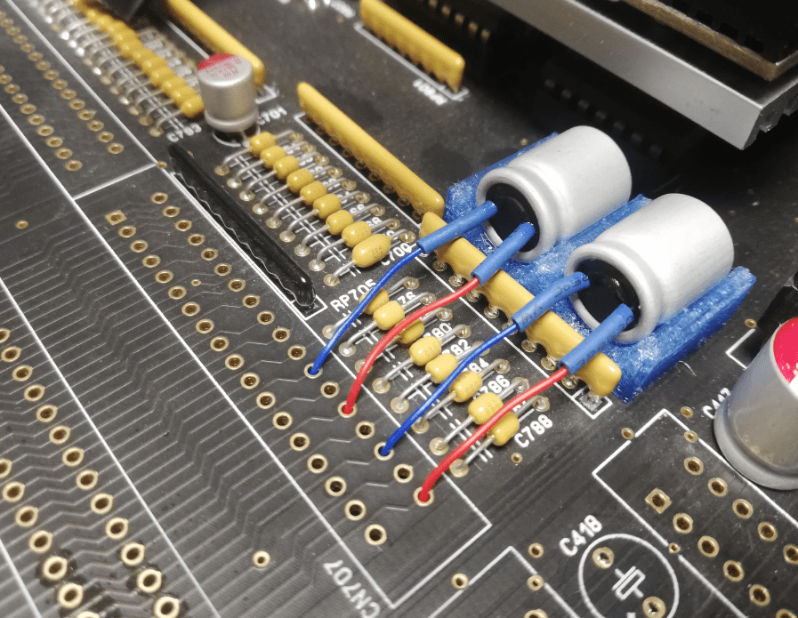
And it fits! Yay!
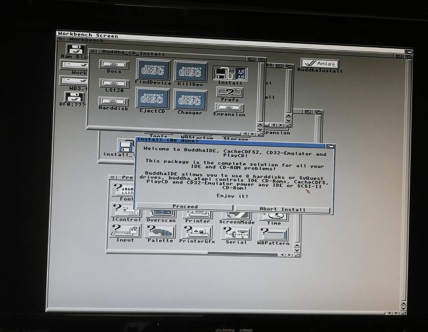
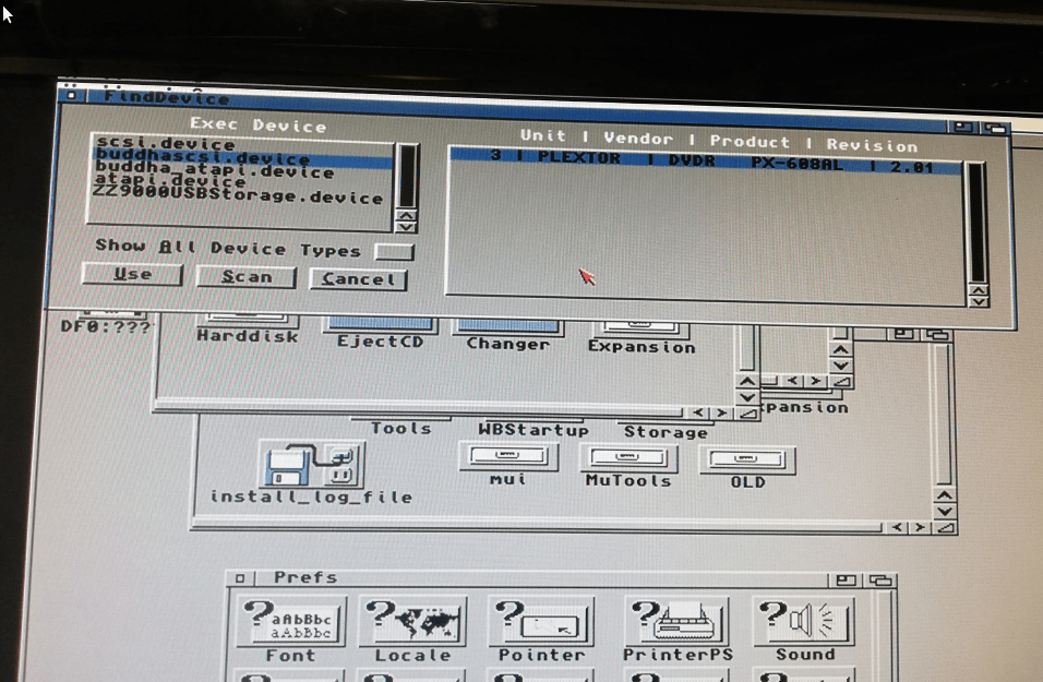
And it works!!! Wooohoo!!
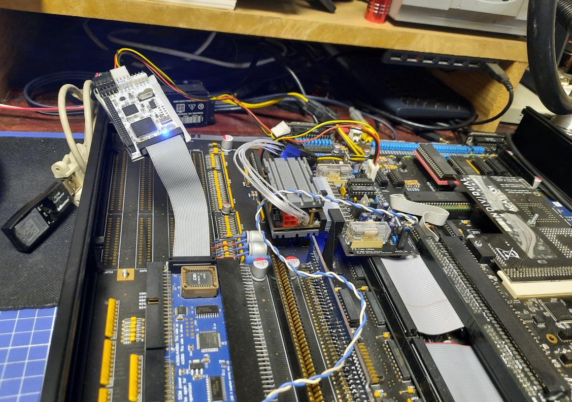
Extreme chaos
From this point on, it is chaos but I think it is necessary to show you how this all goes. I do mistakes that are corrected later but mistakes have to be documented too 😀
I’ll try to comment on some pics a bit more.
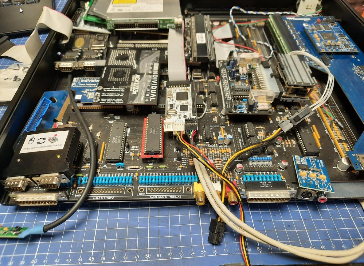
It all happened all of a sudden. The Amiga started to behave weirdly – random hangs or GURUs. I am working on a custom project with lots of mods so it is very hard to control such a situation. It was eventually fixed and I will show how but just have a look at how it all developed 😀
KB and mouse
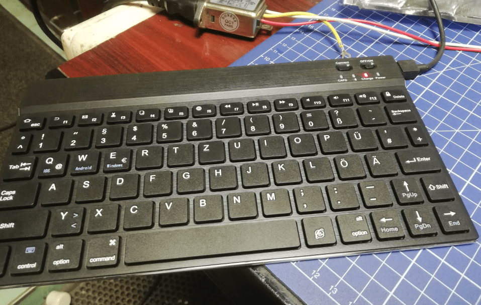
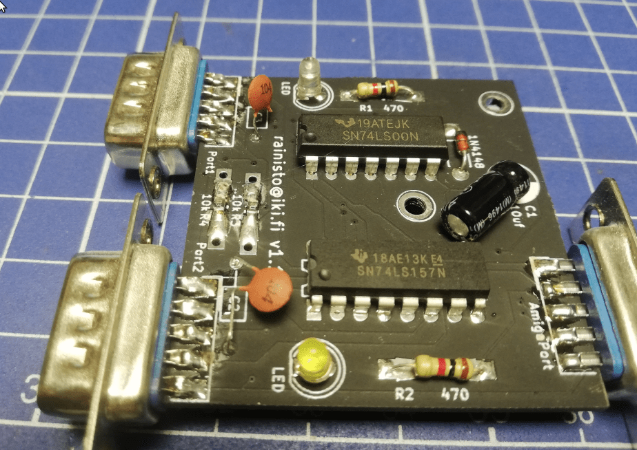
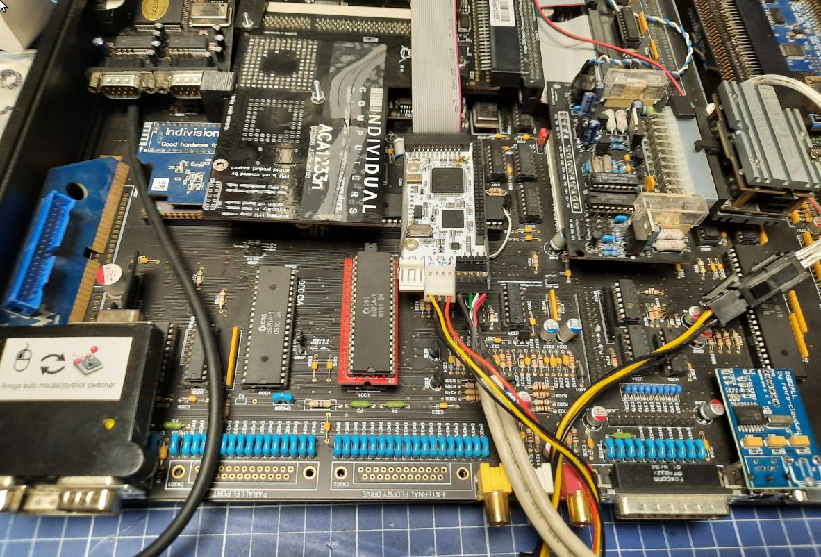
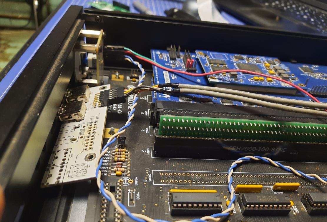
I’ve started working on the keyboard/mouse part. The goal was to somehow connect Bluetooth-driven KB and a wireless mouse but through a mouse/joy auto switcher.
The plan was to use the mouSTer for a wireless mouse connected through a mouse/joy switcher and a SUM 234 adapter for a keyboard.
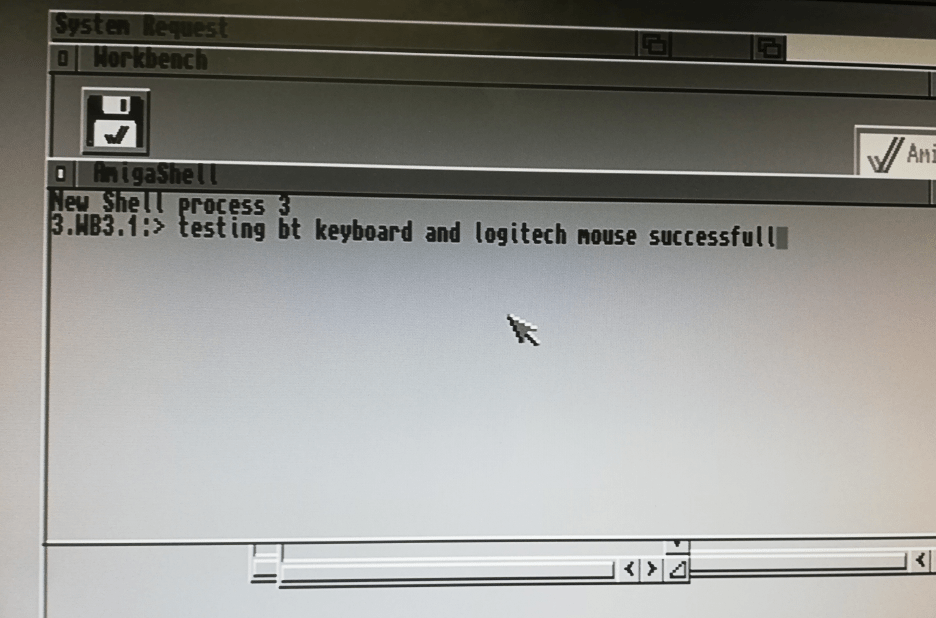
I’ve tested it first without a mouse/joy switcher to see if it works
The BT keyboard was connected through its dongle plugged into a SUM 234. That USB wire is only for charging.
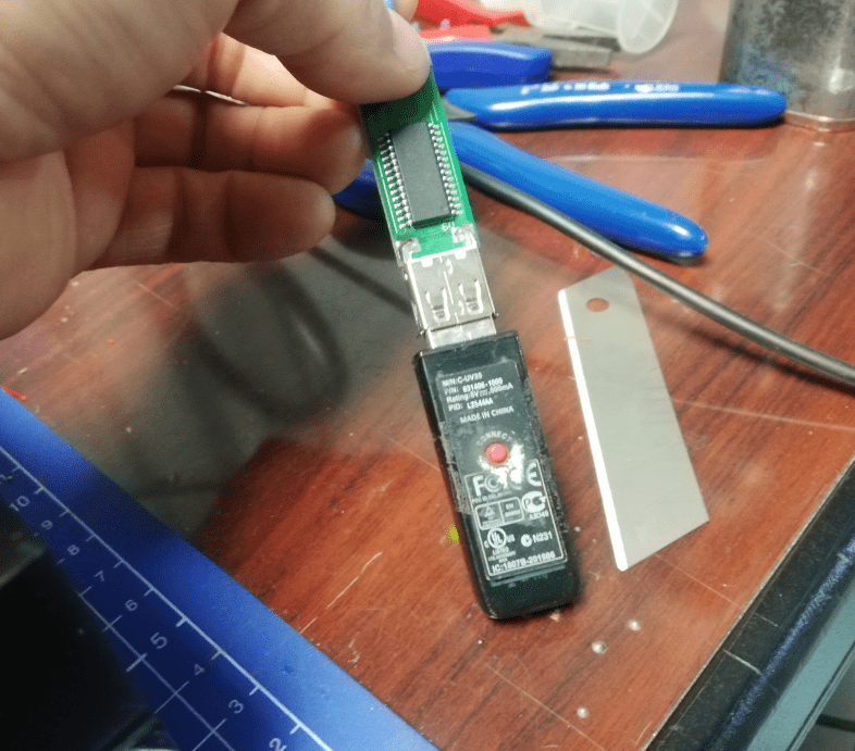
The mouSTer was plugged into a temporarily soldered DB9 socket.
It all worked! 🙂
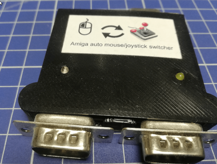
Auto joy/mouse switcher
Then I moved to work on the mouse/joy switcher and things started to become ugly.
GURU meditation … again
The Amiga started to throw GURUs and hung up at random moments. Then, I didn’t know what was wrong, moreover, I didn’t realize how far from problem discovery I was 😀
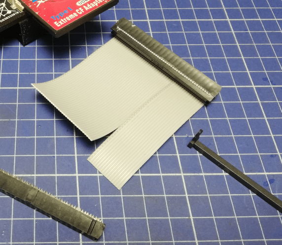
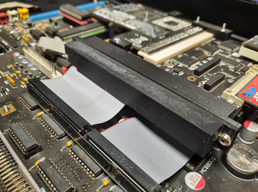
However, I’ve started investigating a ribbon wire connecting ACA500+ and a mobo.
I’ve quickly discovered that there is a problem with one of the wires being slightly off.
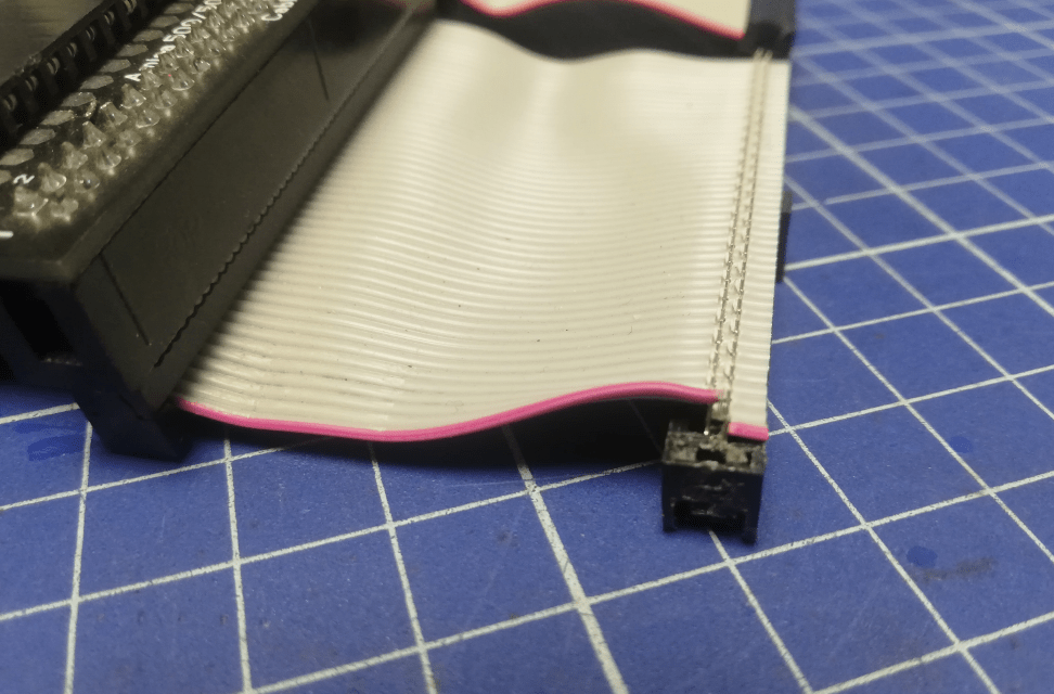
I’ve fixed it by reclamping this IDC connector.
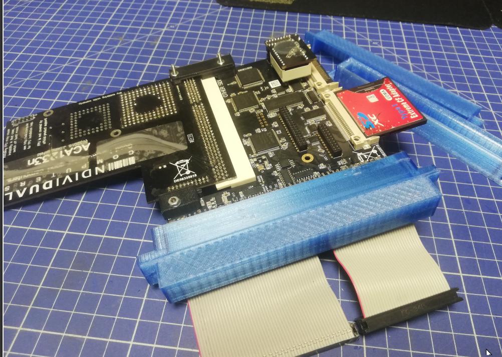
Then I decided to design clamping brackets for this connection to make it more durable. After a few 3D printing sessions, it was done. It was to be reprinted in black plastic later. Obviously, at that point, I didn’t know that I will remove it completely when nearing the end of this issue.
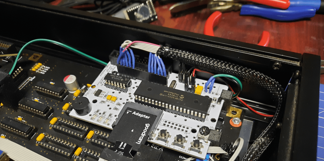
Heatsink
The above work didn’t help so I was like … maybe it is the heat?
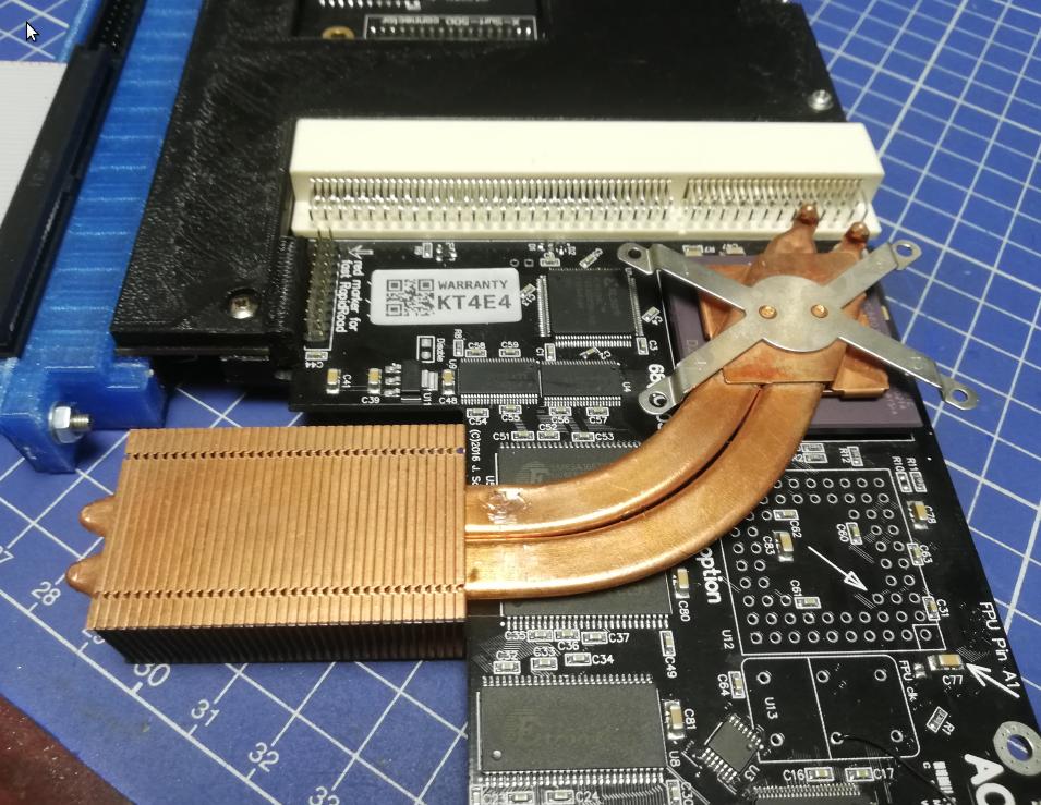
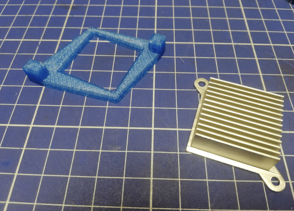
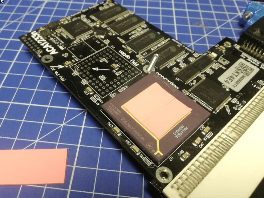
This came to my mind because I started to work with this Amiga a bit longer than quick boot and test if “something” works. I’ve decided that I need to design a cooling solution for a 030 CPU on an ACA1233n.
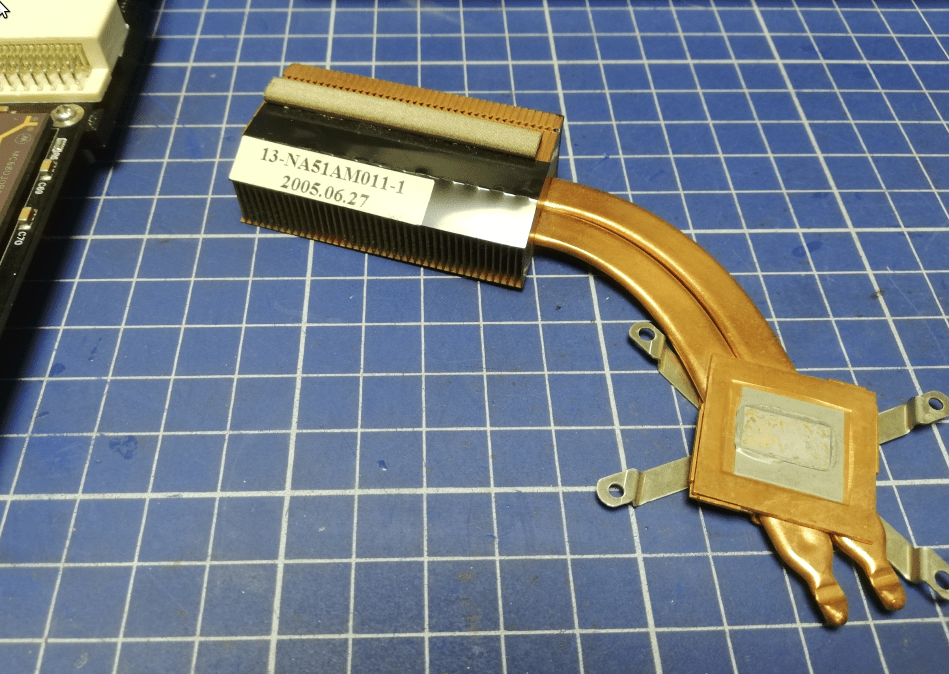
My initial idea was to use a heat pipe stolen from a laptop, but after a few measurements, it turned out to be a dead end.
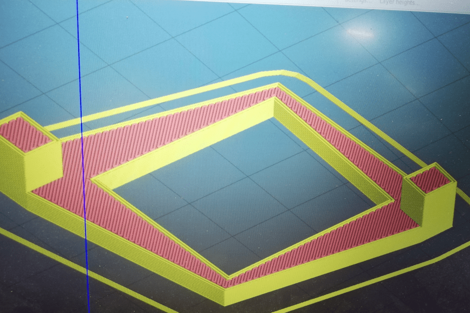
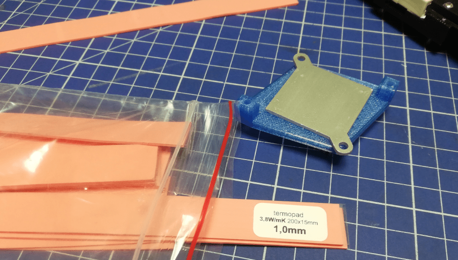
This is when I created a 3D-printed heatsink holder. Obviously (AGAIN!) I didn’t know that I will have to remove it later because of the complexity of this project 😀
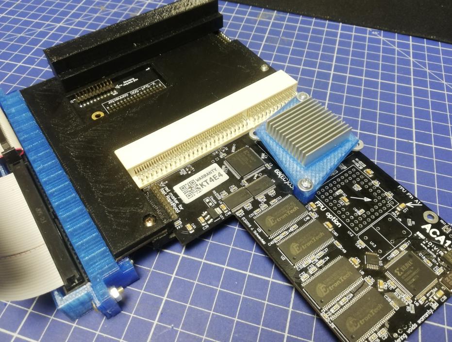
At this point, all came back to normal so I moved to another stage – The clock port adventures!
The clock port adventures
The short story is that while writing this post (and I still have material for another two posts) I am still trying to solve clock port issues. Clock ports are vastly undocumented and the major issue is that devices can be connected in two different ways but … if connected in the wrong way, it results in either a broken clock port or a device …
Let me paint you an idea of what was planned. We wanted to connect several add-ons through the famous Amiga clock port expansion port.
As Wiki describes it “The port is a remnant of an abandoned design feature for the addition of internal RAM and a clock for timekeeping. However, it was later widely used as a general-purpose expansion port by third-party developers for devices, such as I/O cards, sound cards[1], and even a USB controller.[2] Although a real-time clock can be connected to the port, the clock was typically added by other means (usually integrated on CPU or RAM expansions) which leaves the clock port free.[3]“
What’s the plan again?
Amiga 2000 doesn’t have a clock port but we have expansions that have it! Through these expansions, we can and want to connect four devices:
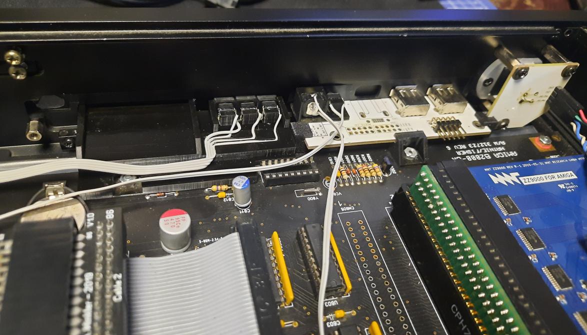
I’ve started working with RapidRoad USB and the best way (for this project) was to connect it to a clock port located on an ACA1233n. However, it didn’t work at all. The expansion was simply not detected. However, it was detected through an ACA500+ clock port. Did I mention that I’ve killed that expansion (RRUSB) twice lol? Fortunately, Jens of iComp designed this one nicely and it was just a matter of replacing fried resistors that were placed there for morons like me 😉
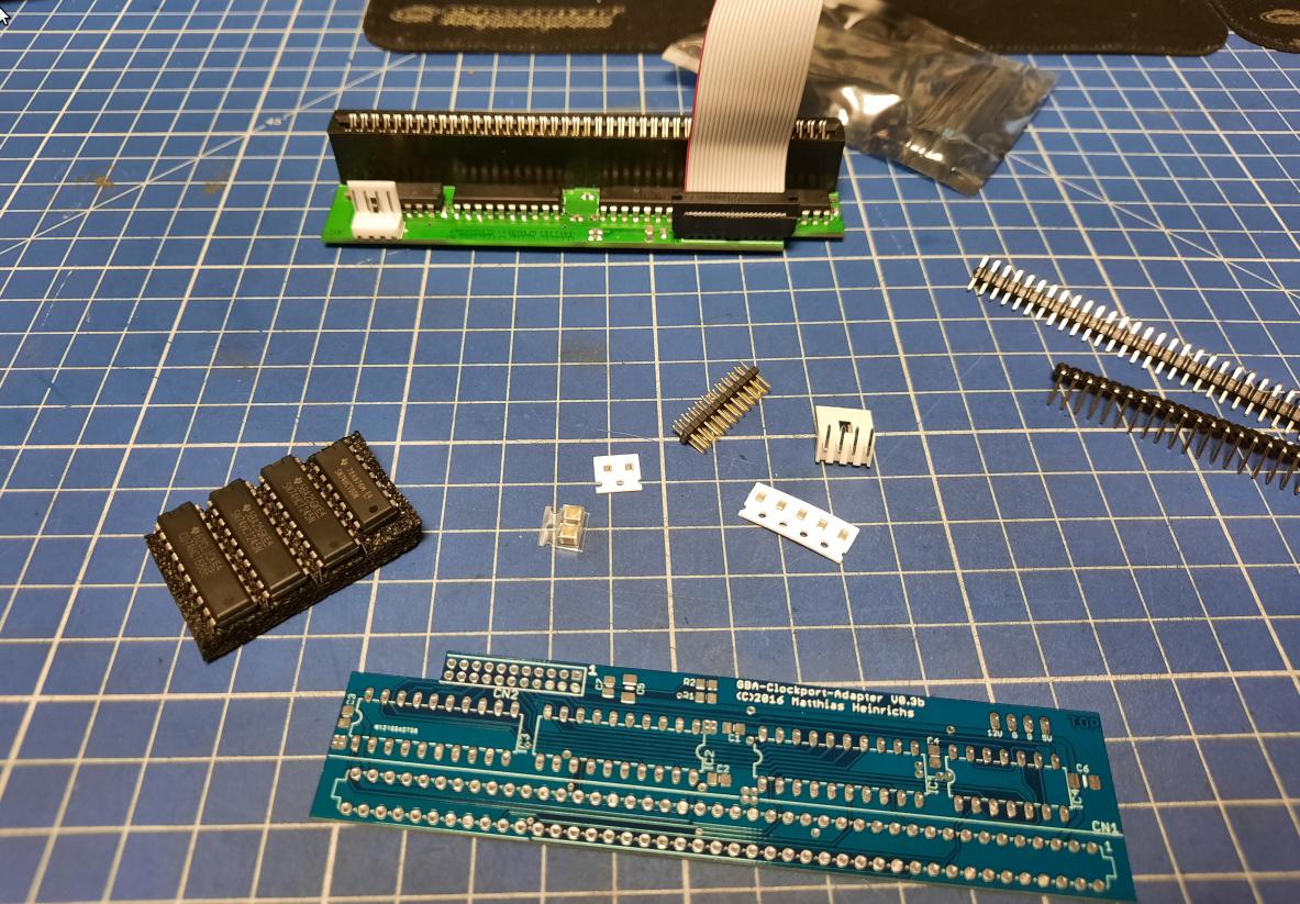
Zorro clockport adapter
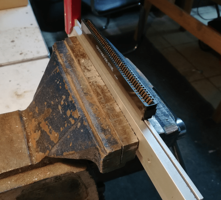
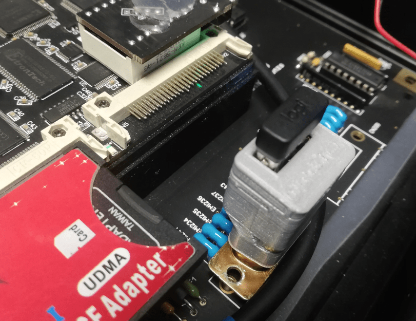
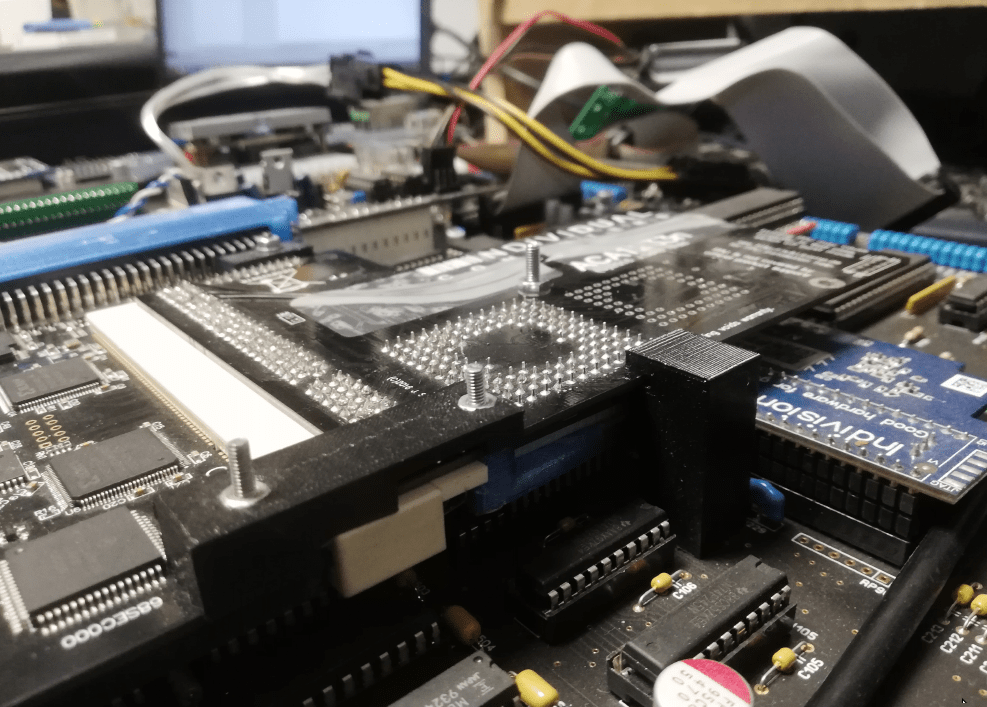
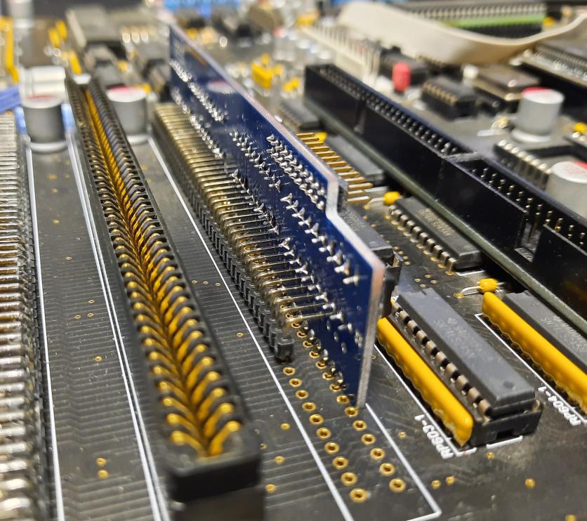
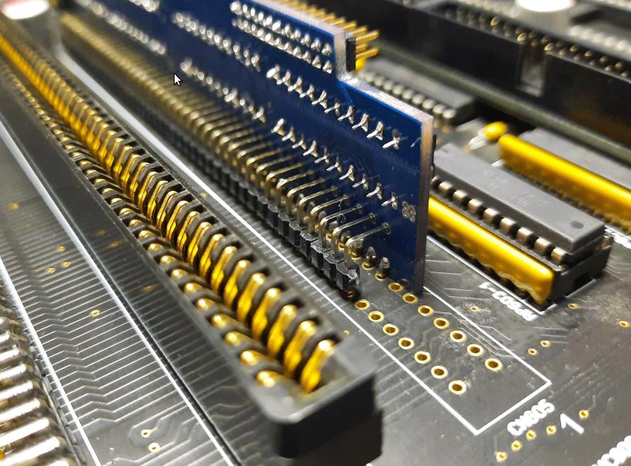
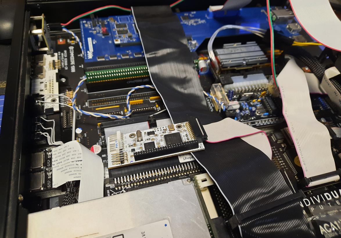
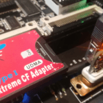
Anyway, MrTrinsic wanted me to test a simple Zorro to clock port adapter and he’d sent it along. It was a bit different solution that we’ve tried to use in an Amiga 1000 Phoenix project but still, it was not designed for an A2000 😀
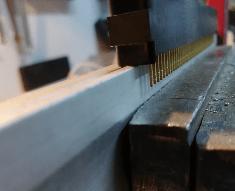
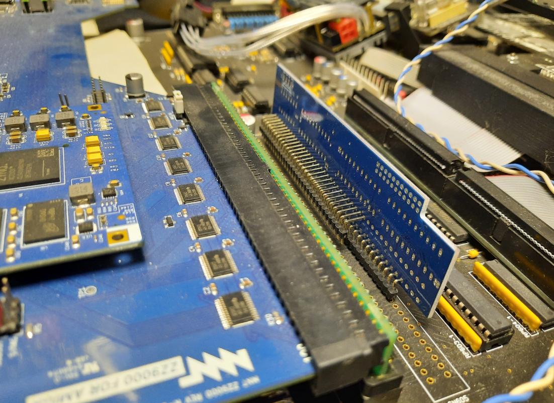
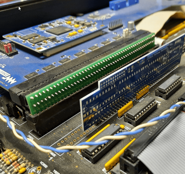
I was a bit against this test because I knew that gold-plated (ENIG) pads on a MoBo will hold these gold pins strongly.
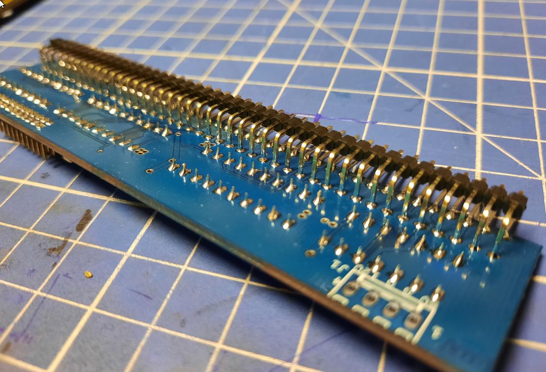
However, I did it! I just had to slightly trim the original angled gold pins to optimize room usage.
In the meantime, I’ve 3D printed fresh and BLACK ACA port covers.
Did I mention CHAOS already?! 😀

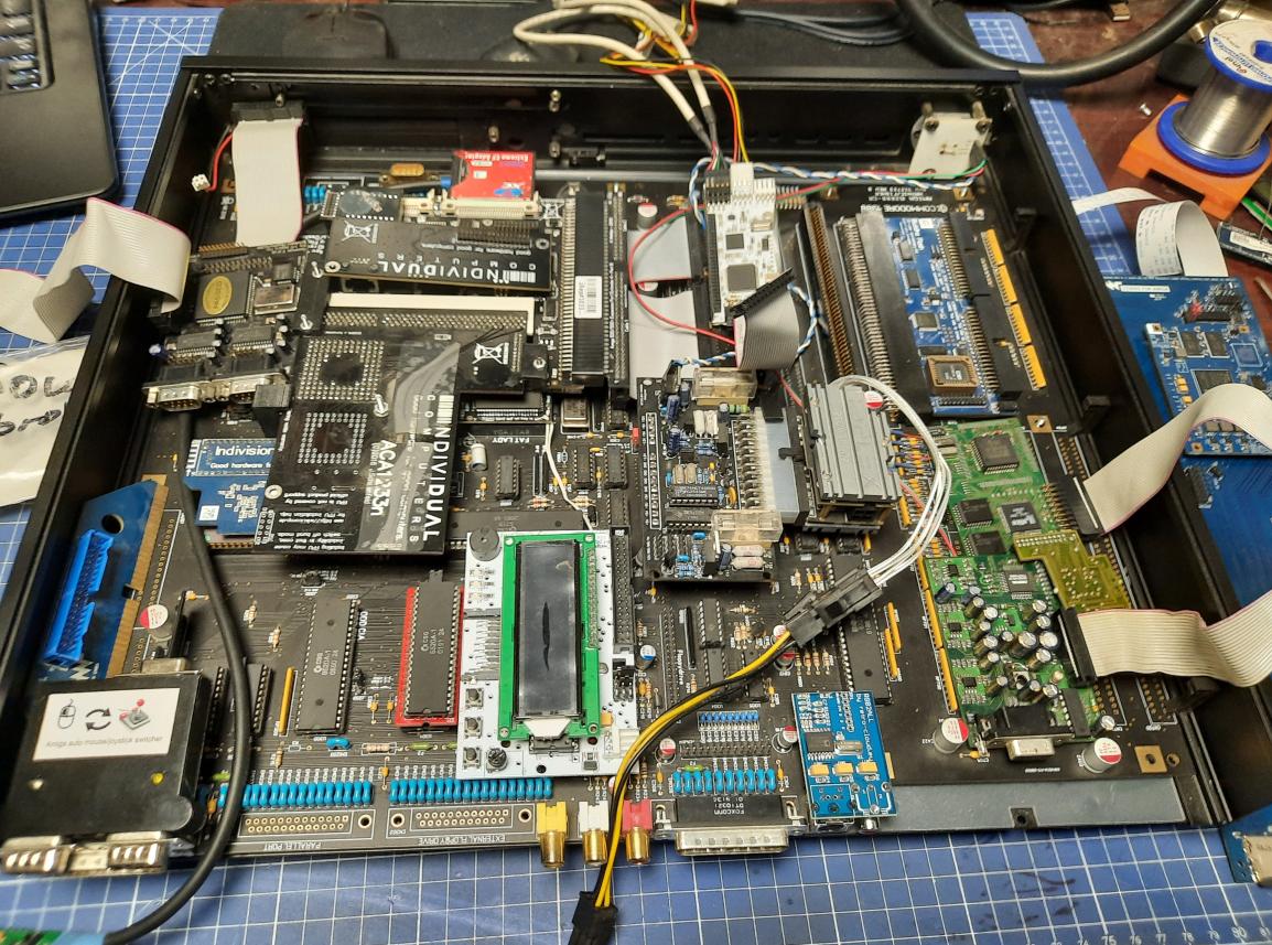
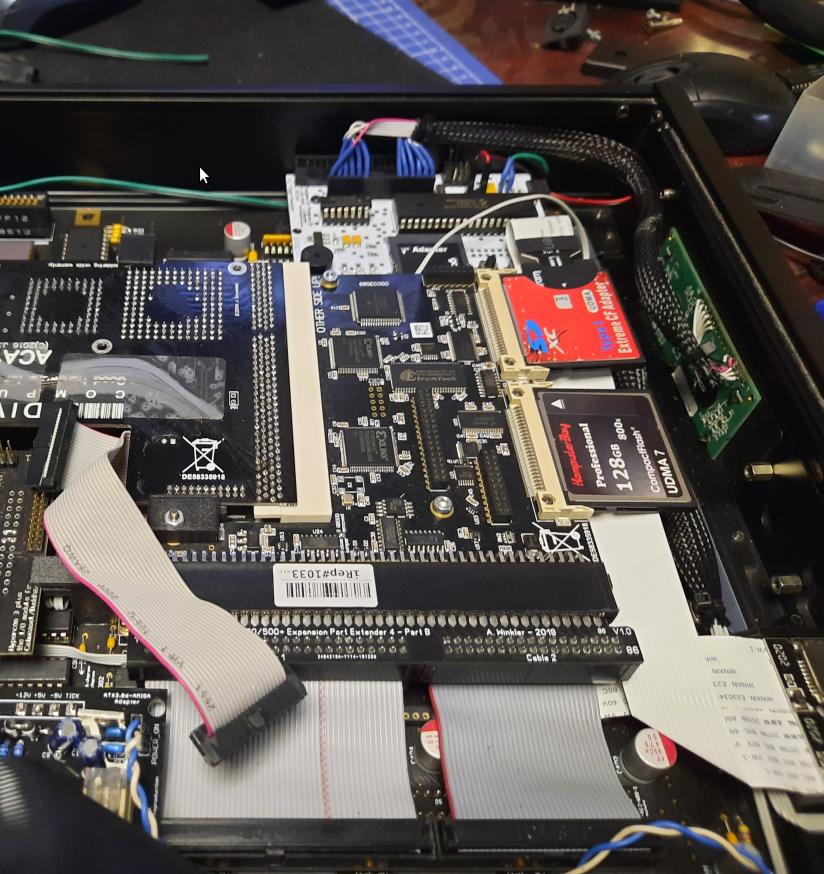
ACE expansion
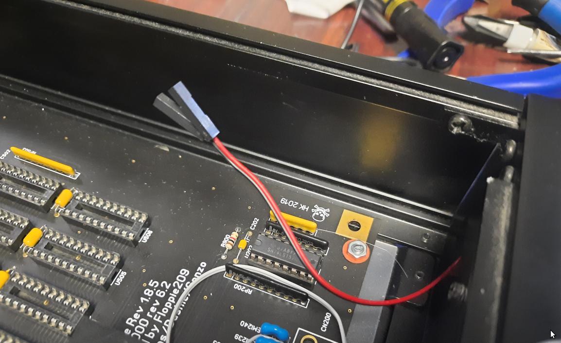
This project is so long and complex that I don’t even remember why we’ve abandoned this expansion, but that is not important since the Amiga started to randomly crash again …
This happened after ANOTHER re-assembly (after soldering and desoldering the clock port card) and this time after a few days of fiddling, I’ve narrowed it down to an ACE expansion – FatAgnus replacement.
However, I didn’t figure out what exactly causes these random crashes, even though it was already visible on the pic below … but more on this later.
After re-seating the ACE, the problem kinda stopped so I could move on to clock port tests again.
The next stop is Buddha Flash which has a clock port. After some tests, it turned out that Rapid Road USB works nicely through it.

Anyway, I’ve left these problems for later because time flies and had a lot to do.
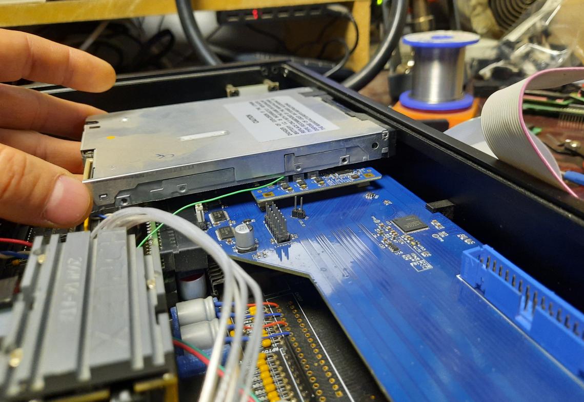
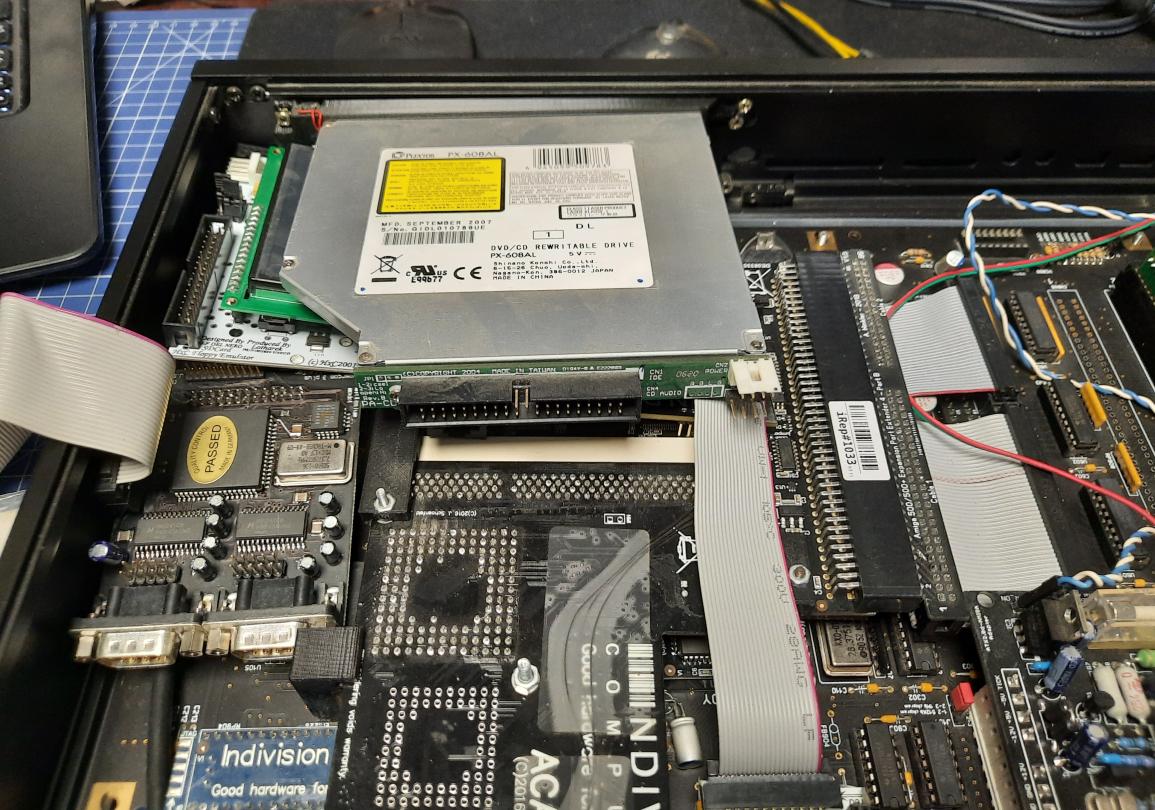
Add-on placement
Next step – add-on location, which means another measuring round.
Various options were considered.
Chaotic front panel job
I’ve started working on a front panel. I’ve divided it into a few parts – The power button(already described in previous posts), LCD, Mool logo, and some more stuff 😀
Let’s start with …. everything lol
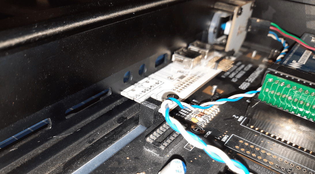
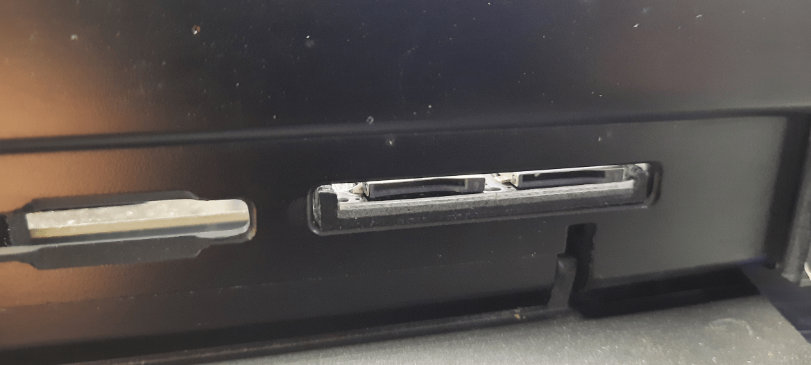
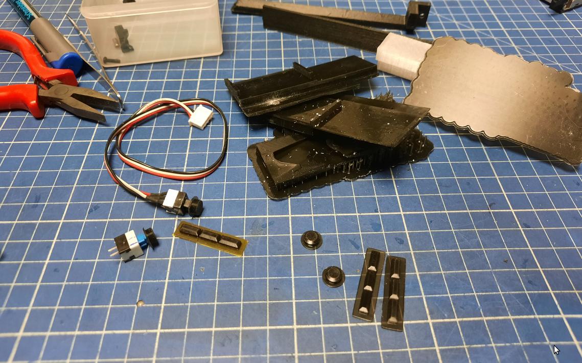
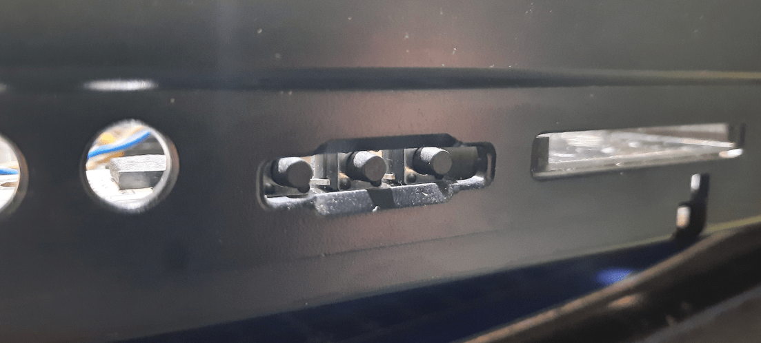
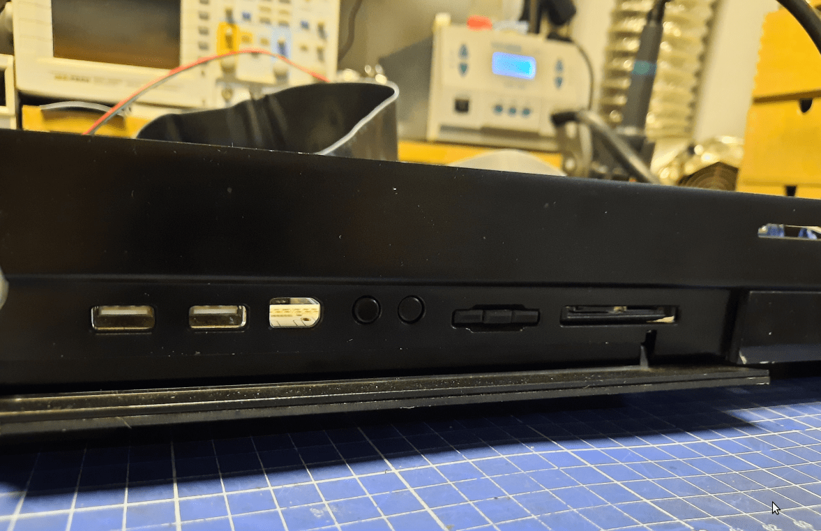
The front panel part hidden under a flap has many proper holes (no pun intended lol). The plan was to re-use almost all of them but I had to figure out how to approach this first.
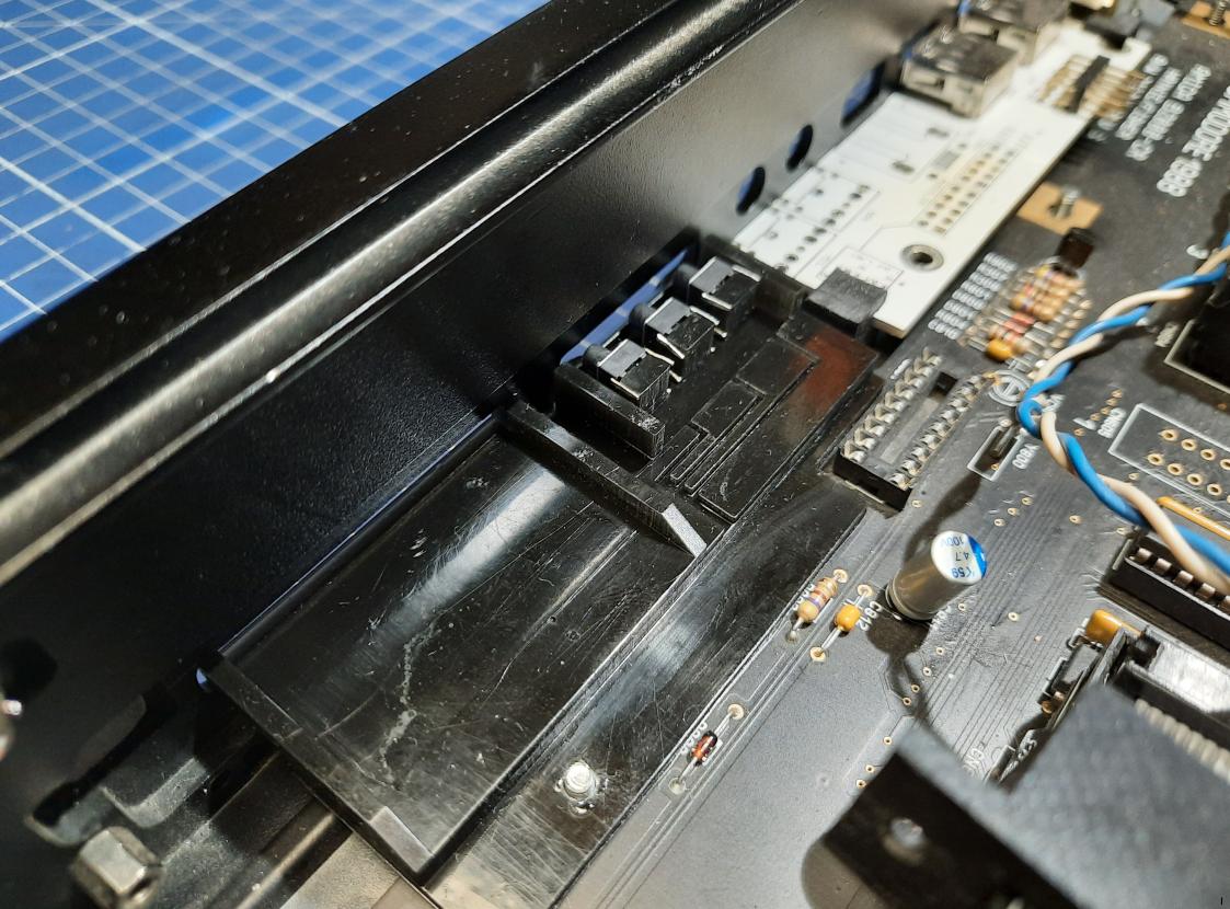
I’ve come up with an idea to use the original PCB that was supplied with this PC/Amiga case but I had to desolder some components, as I don’t need a firewire nor audio jacks, and cut it to a proper size. This is how I did this.
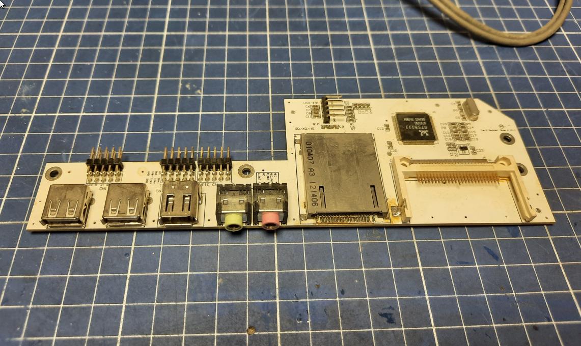
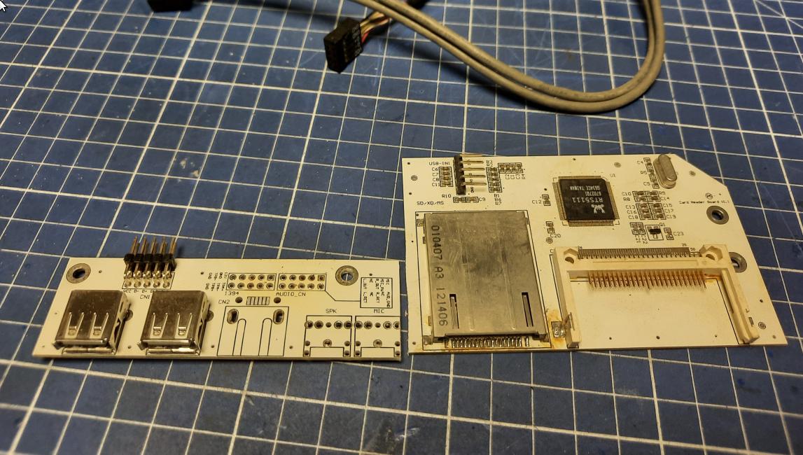
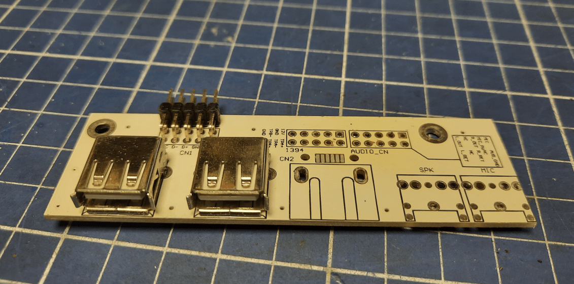
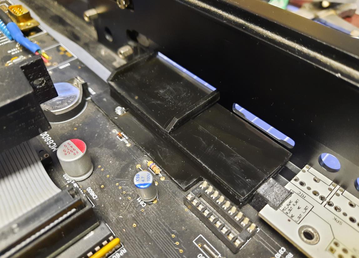
I designed a few studs/brackets to hold it in place
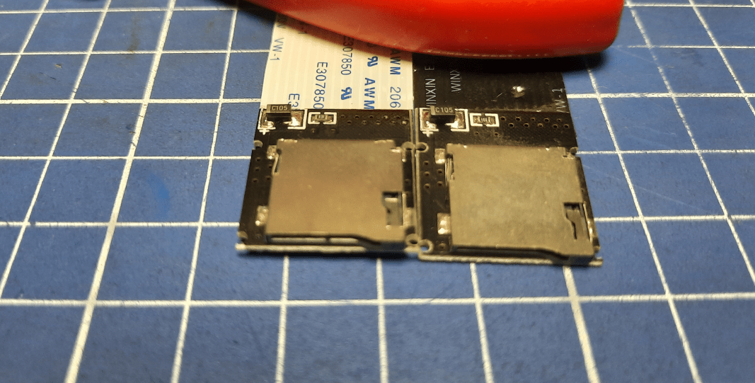
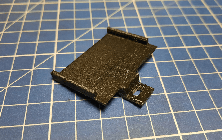
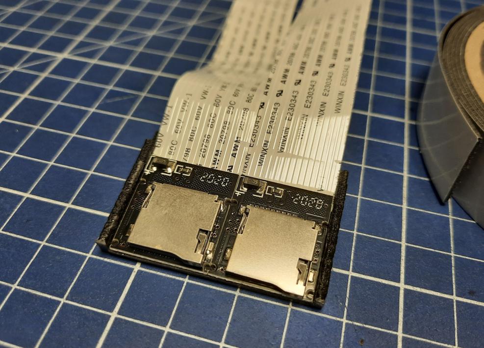
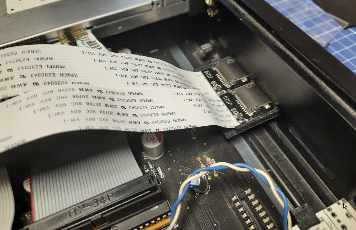
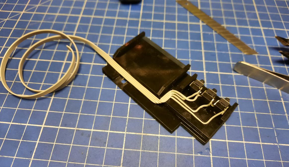
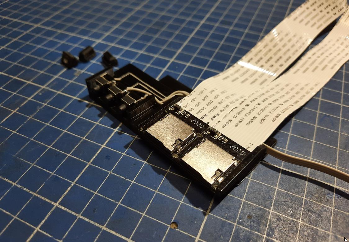
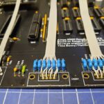
Next, I’ve 3D printed a simple holder for two SD card slots with flex-wire extenders to connect to ACA500+ and HxC.
The idea was to put both PCBs in a CF card slot hole.
Back to a drawing board …
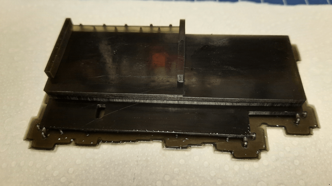
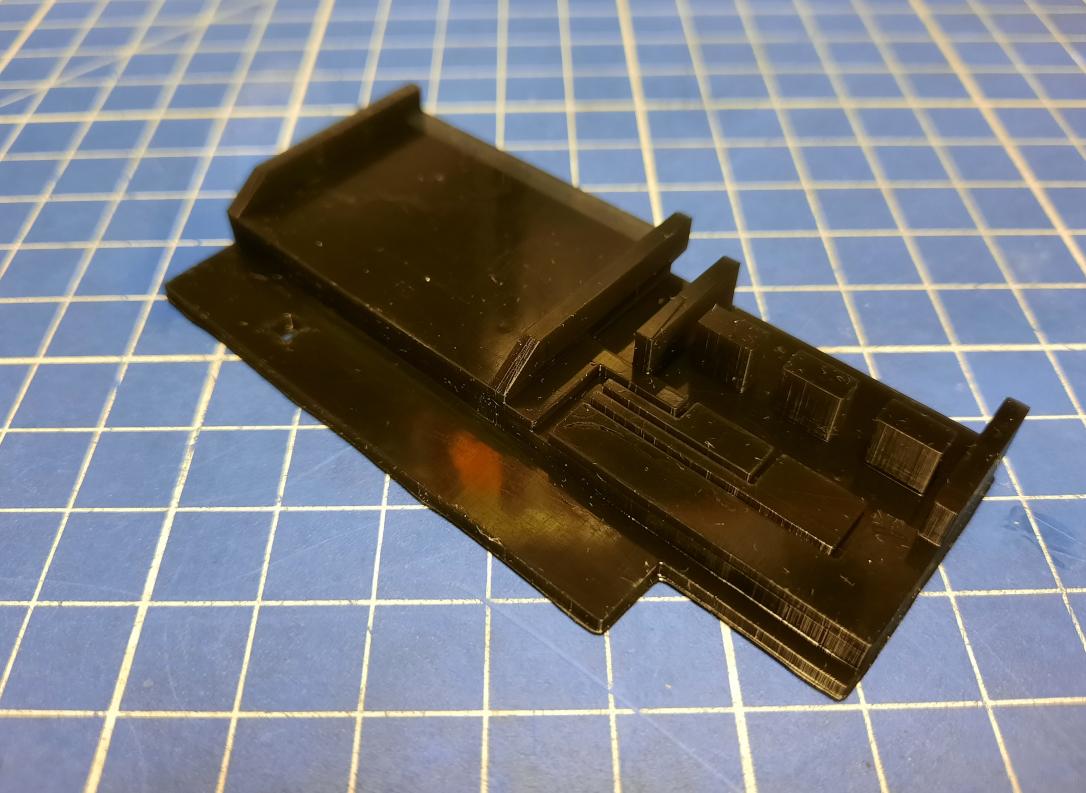
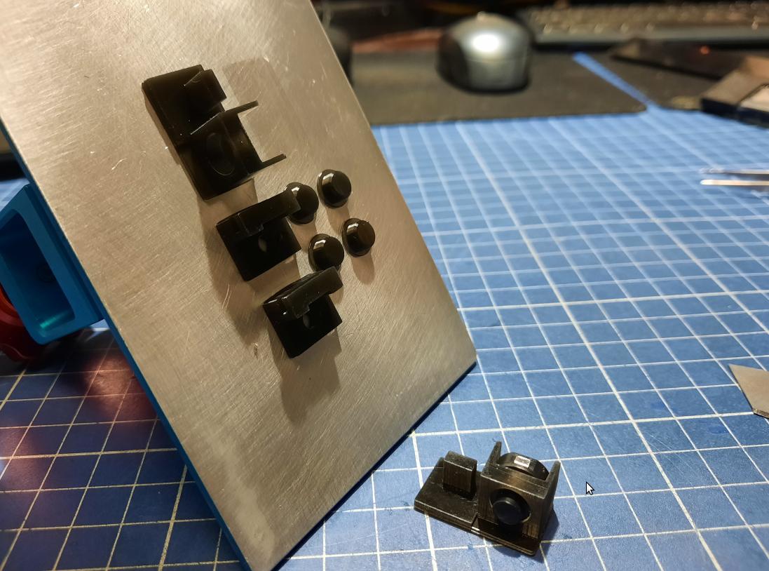
I’ve decided that I’ll rework this panel and 3D print it from UV resin. Below, is the prototype.
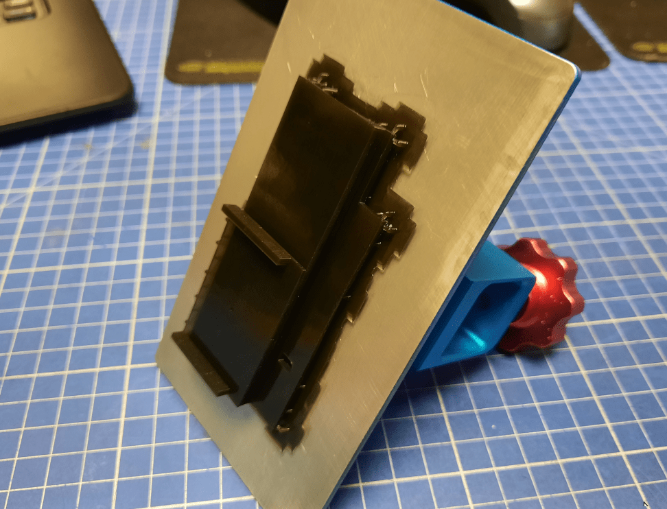
Then, the second, third, and so on 😀
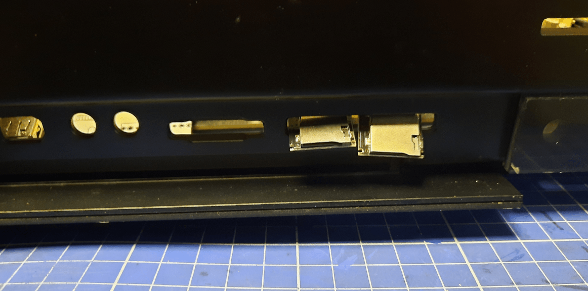
Until I came up with a proper solution.
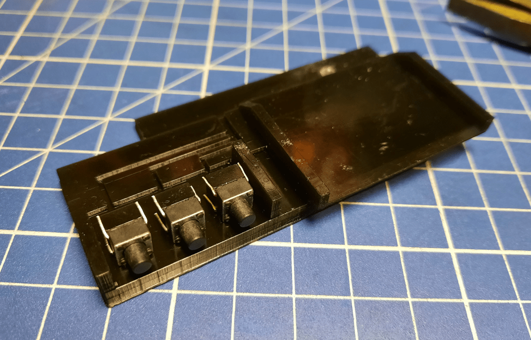
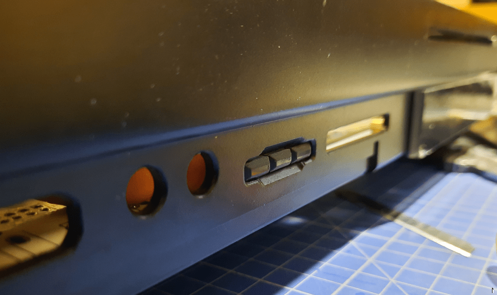
From left to right – USB slot 1, USB slot 2, EMPTY, DiSmo button (AVA500+), Bootselector, three HxC buttons, and two microSD card slots.
Hxc and the Mool logo
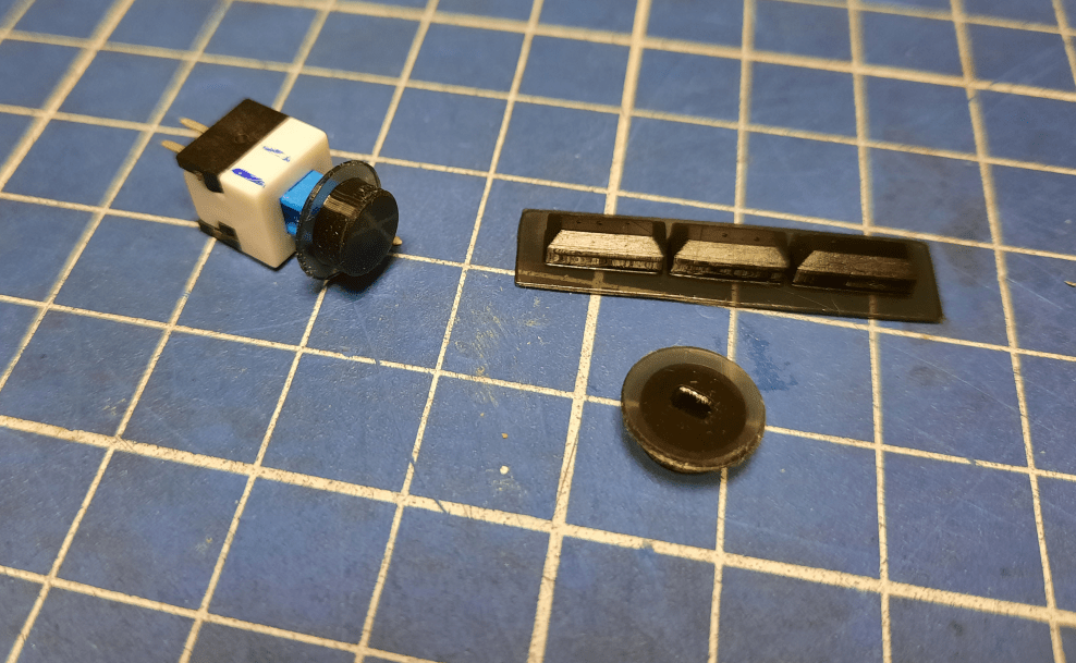
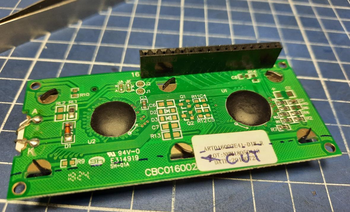
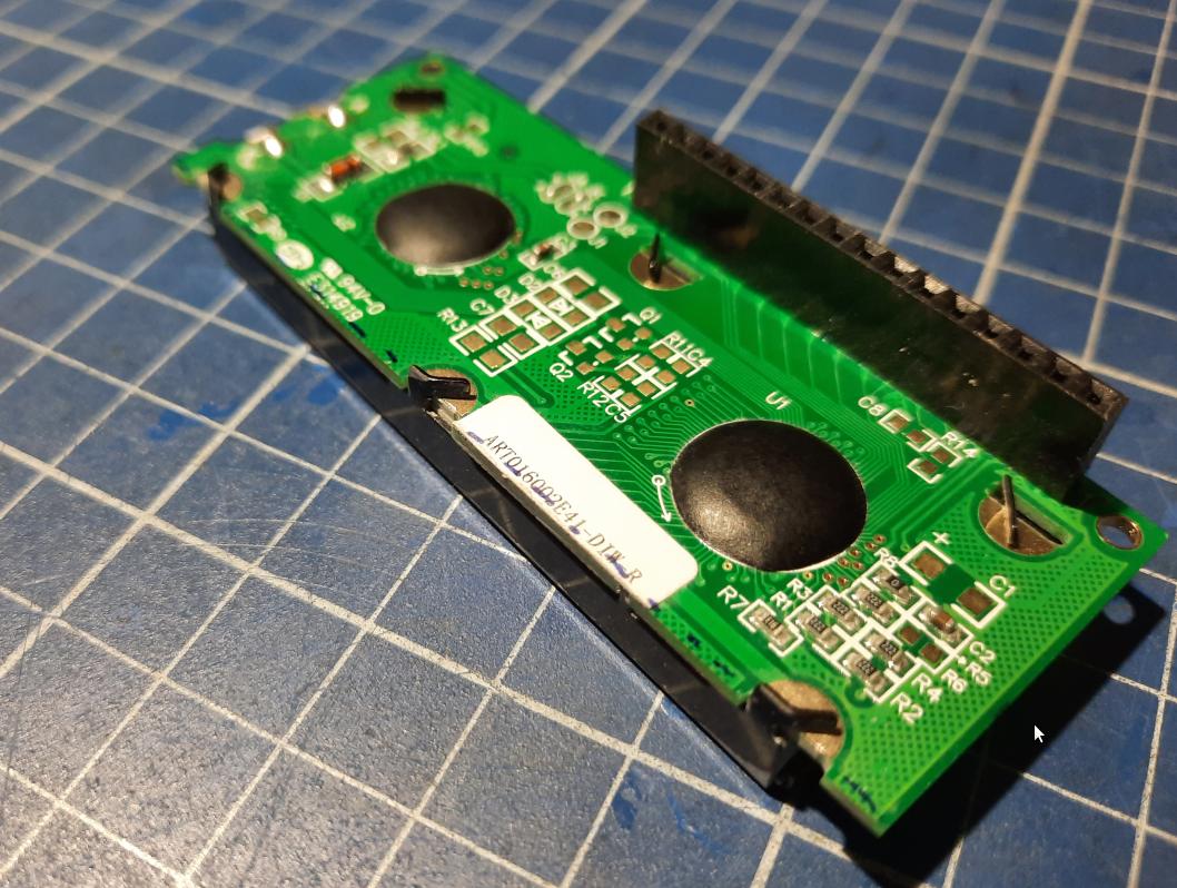
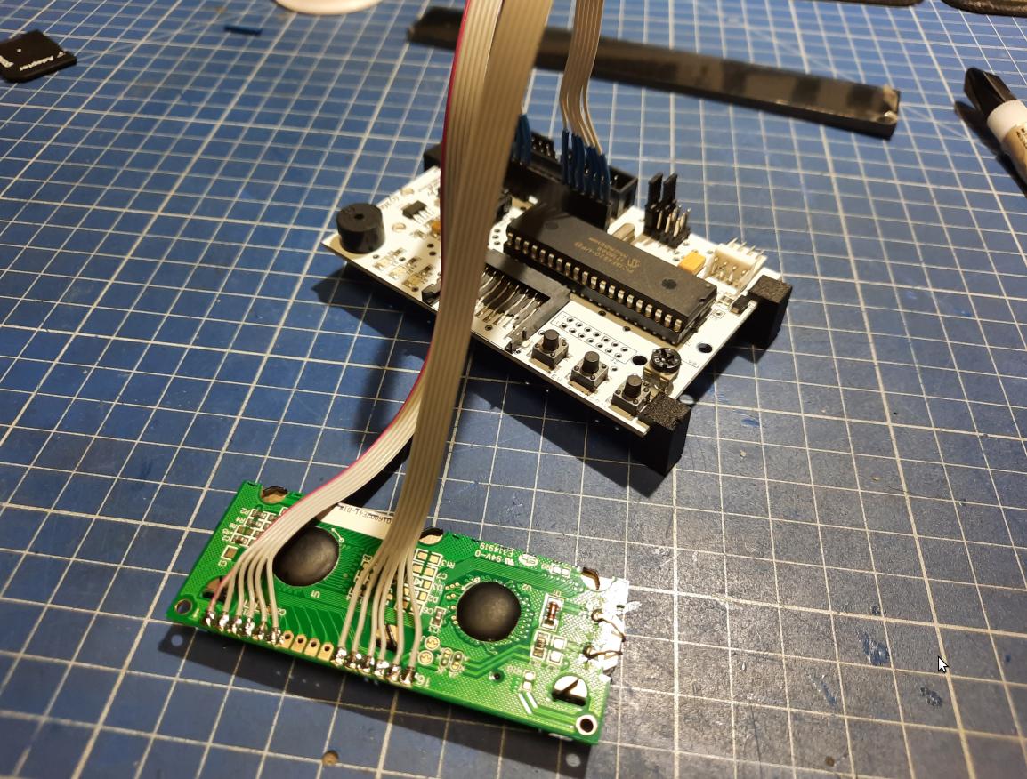
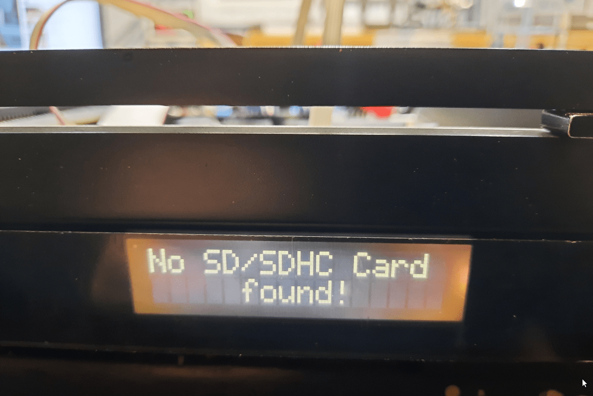
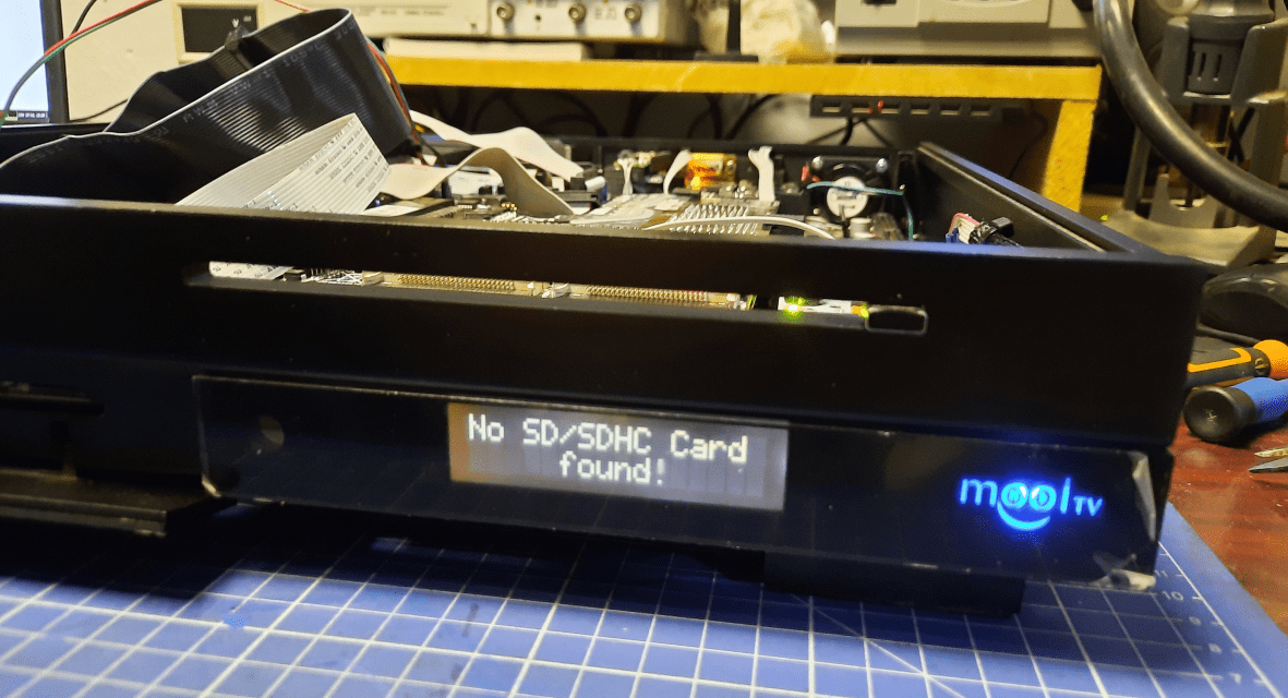
Next in line was a panel on the right. I wanted to put HxC LCD there and decided to work on the Mool logo while it was disassembled.
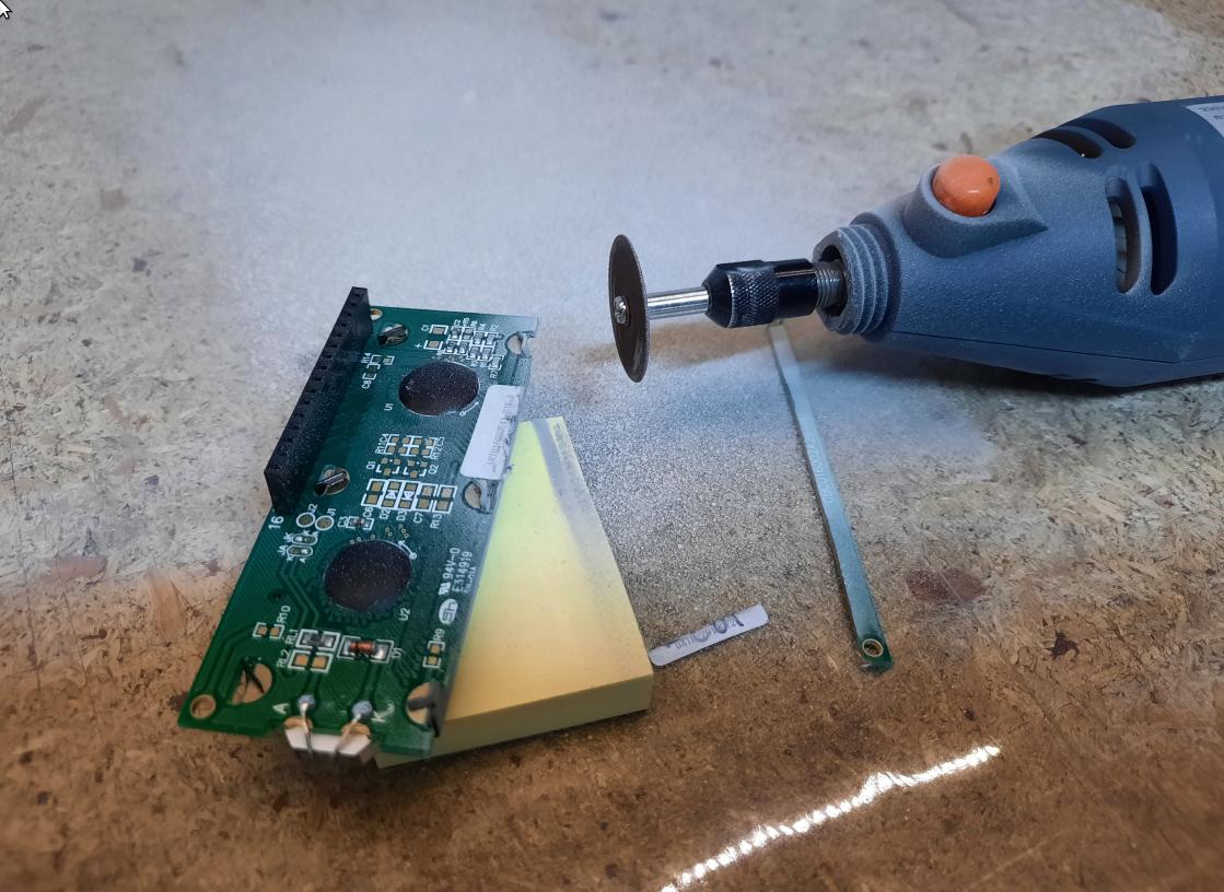
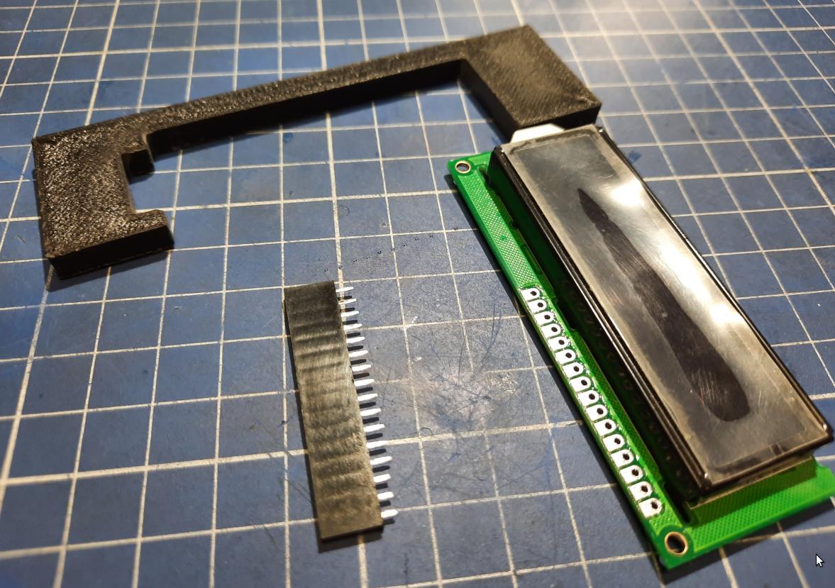
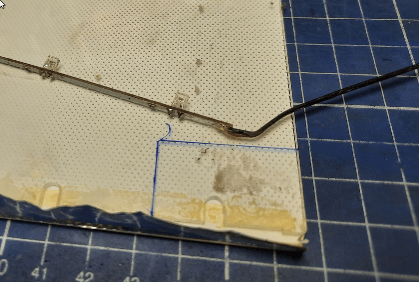
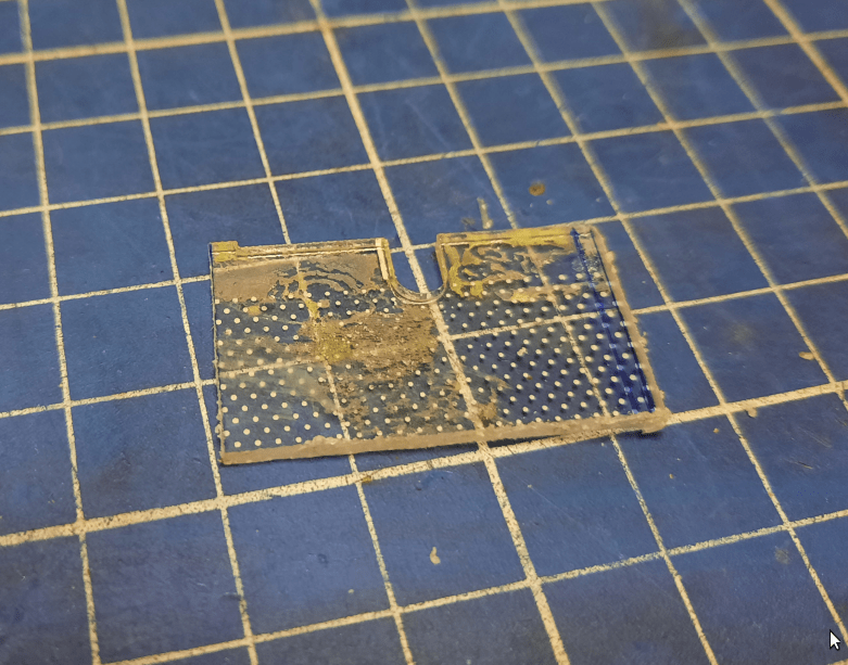
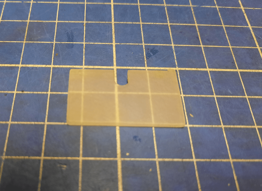
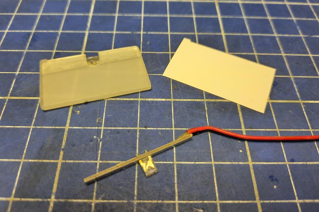
The problem was that the original LCD is a bit too big. Fortunately, I was able to trim it to the proper size. Then it was only a matter of designing and 3D printing a bracket for it.
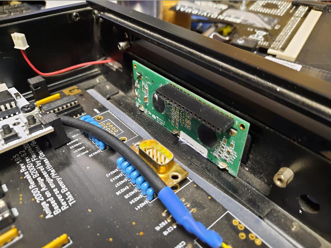
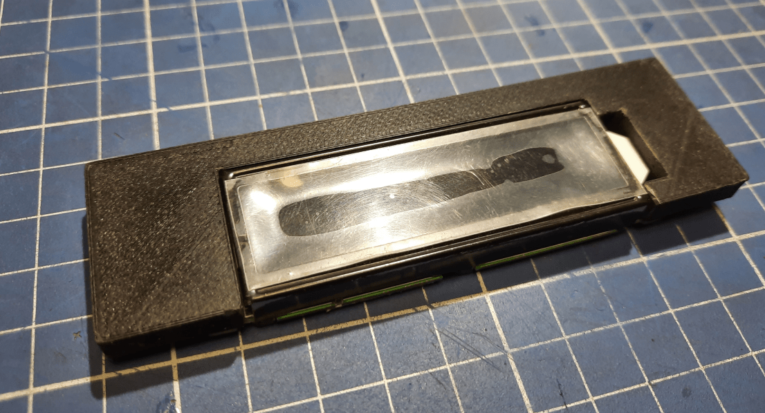
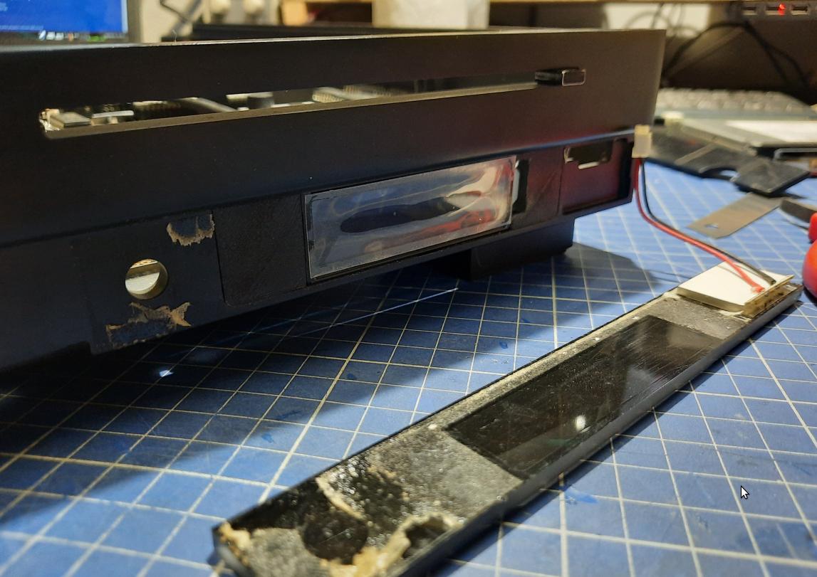
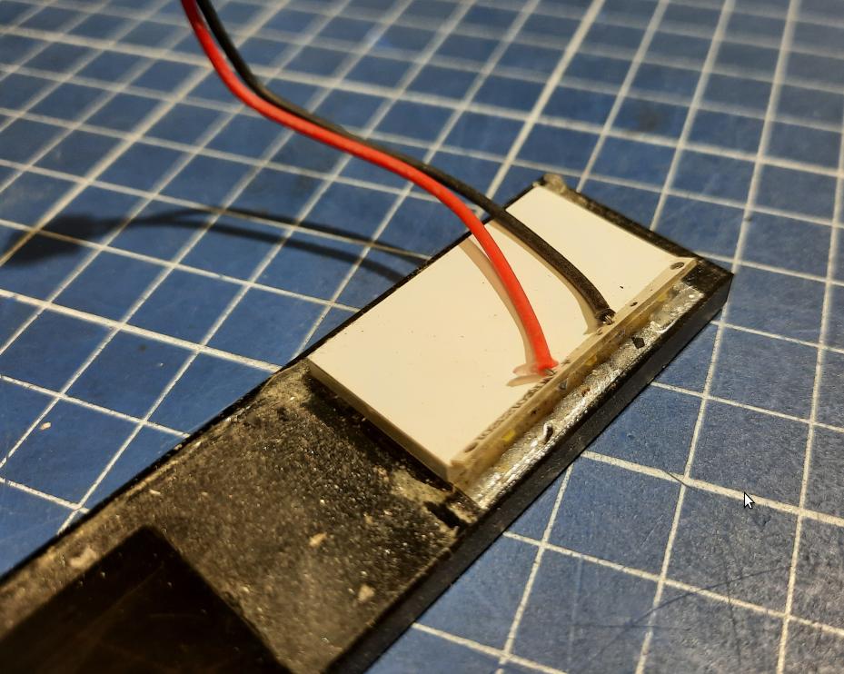
The original backlight had to be changed to blue. I made it from scratch using some parts that I had on the shelf.

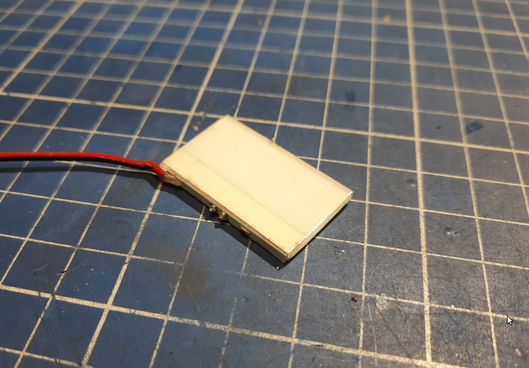
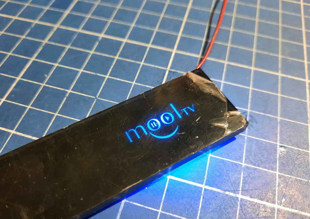
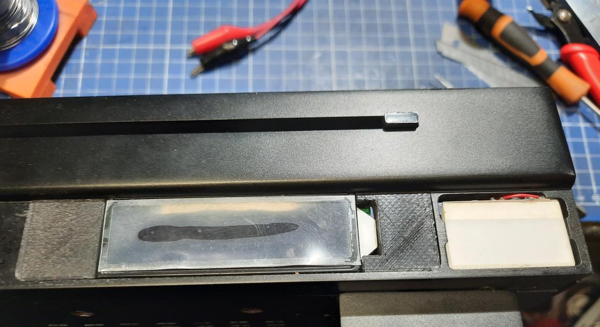
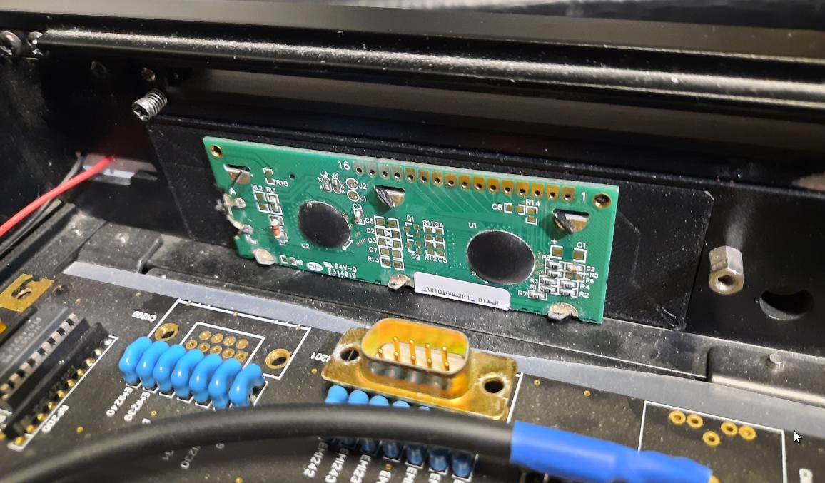
The Mool logo will be powered via a HxC 5V rail to save space. I’ve also placed HxC in its target space using some 3D printed studs, soldered front panel wires of control buttons, and routed a flex microSD ribbon wire to it.
The outcome.
End of PART 4
You’ve reached the end of part 4 of the Amiga Tesseract project. Stay tuned for more episodes of this build as at least two posts are coming 😀
Outro
If you want to get the retro gear I am manufacturing or hardware modules, please visit shop -> https://retrohax.net/shop/
Please support my work by commenting here and on our Facebook or Twitter pages.
Just incredible!!!
:O :O :O