… or still not the end
Intro

Links to the previous posts of this project:
Let me continue with this build. This time it is all about details and bugs 😀
Broken Indivision ECS v2
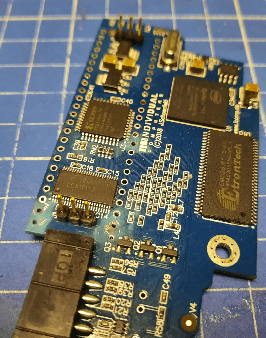
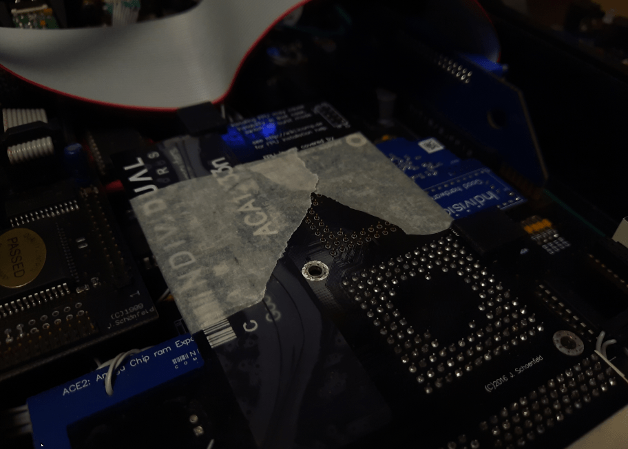
After another round of testing, I started getting issues with video output.
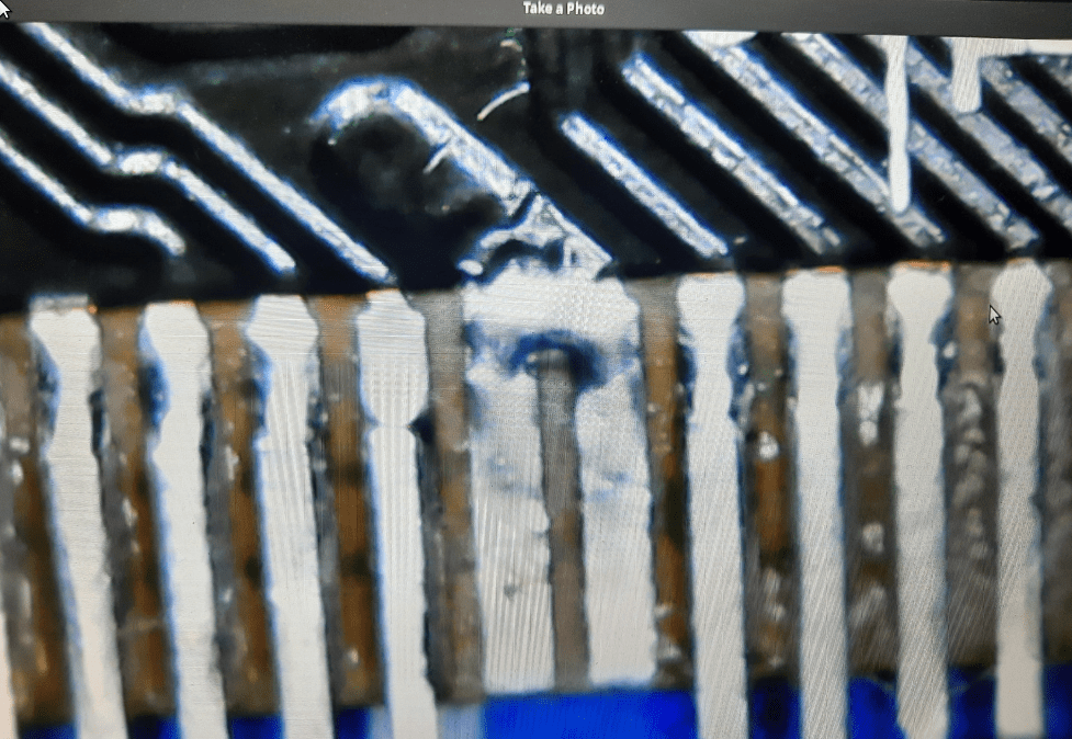
Obviously, I wasn’t aware of what caused it but I quickly narrowed the problem and found out what was it. Yup, Indi v2 started to misbehave. After a while, I found the problem. Turns out that, after intensive testing – removing and inserting it into a socket – some traces and vias on a PCB failed.
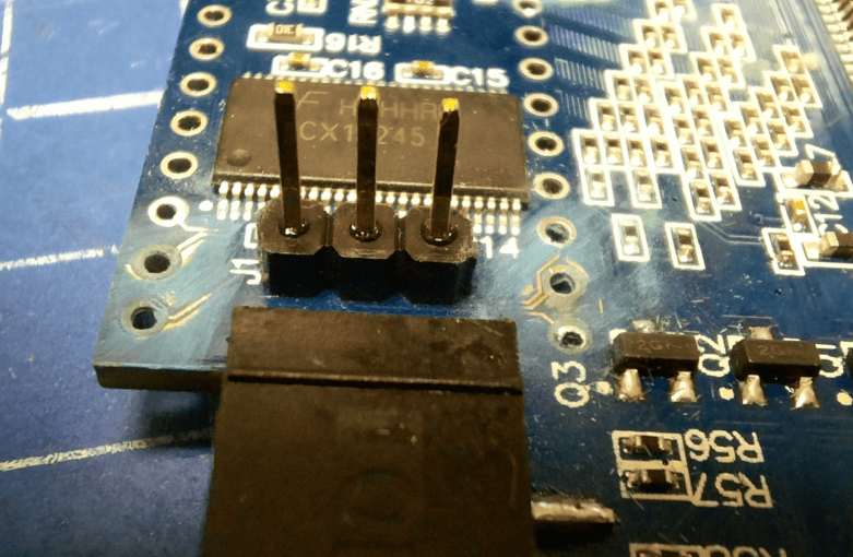
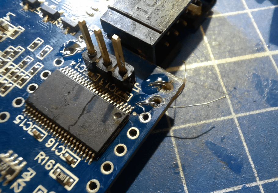
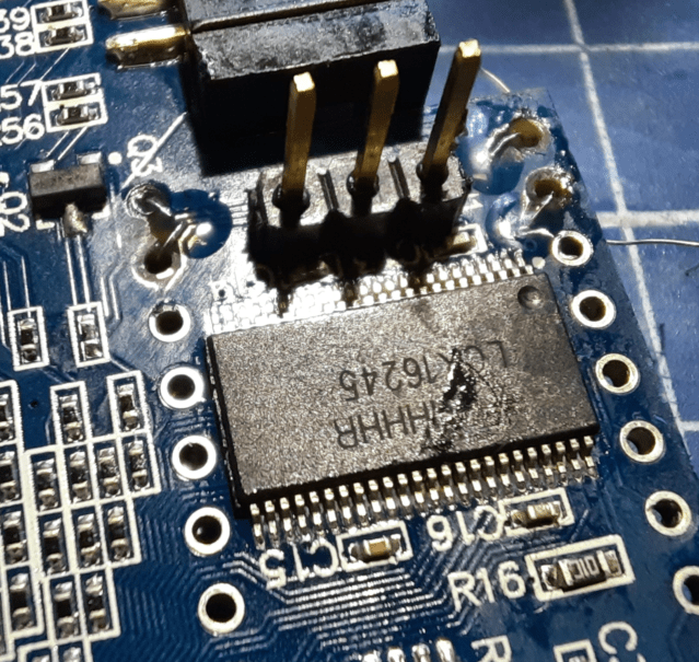
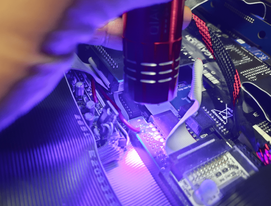
I’ve tried to fix that by soldering a very thin copper wire but it didn’t help on the first attempt.
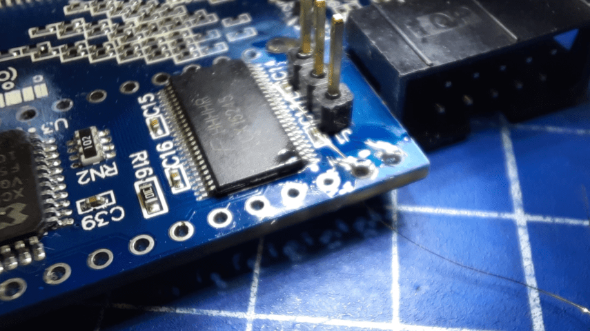
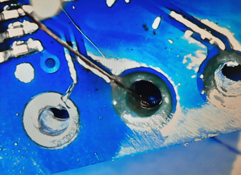
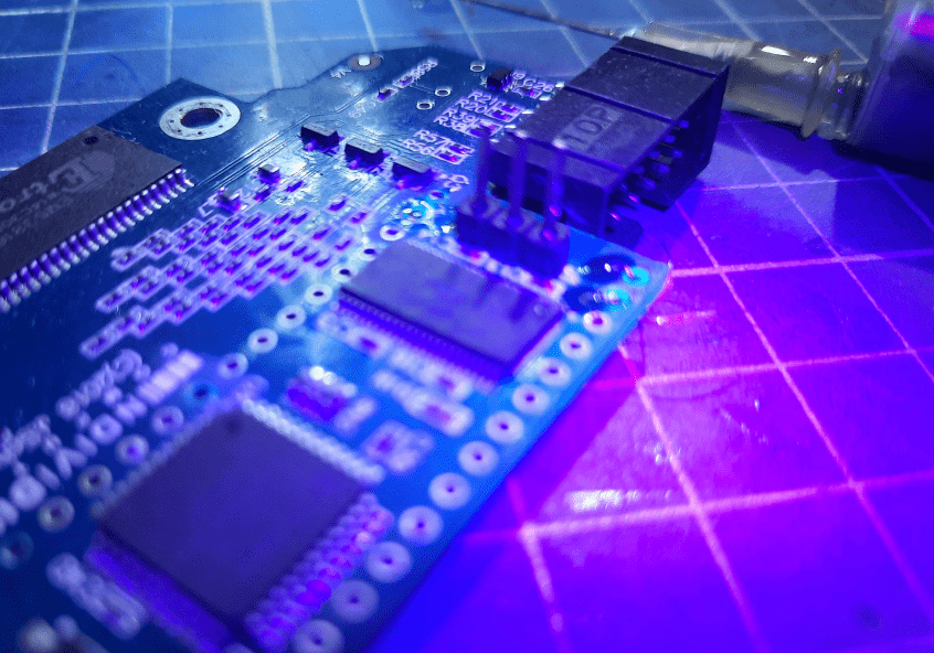
Once all four wires were soldered, I applied some drops of UV resin and cured it to make it secure.
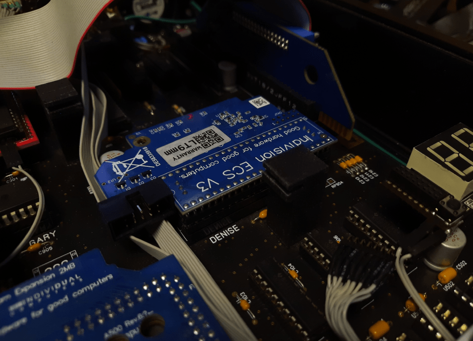
Unfortunately, that didn’t work well and would require more time and tinkering. Mr.Trinsic decided that he doesn’t want to include such a worn-out mod and ordered Indy ECS v3 … which obviously, fixed the issue 😀
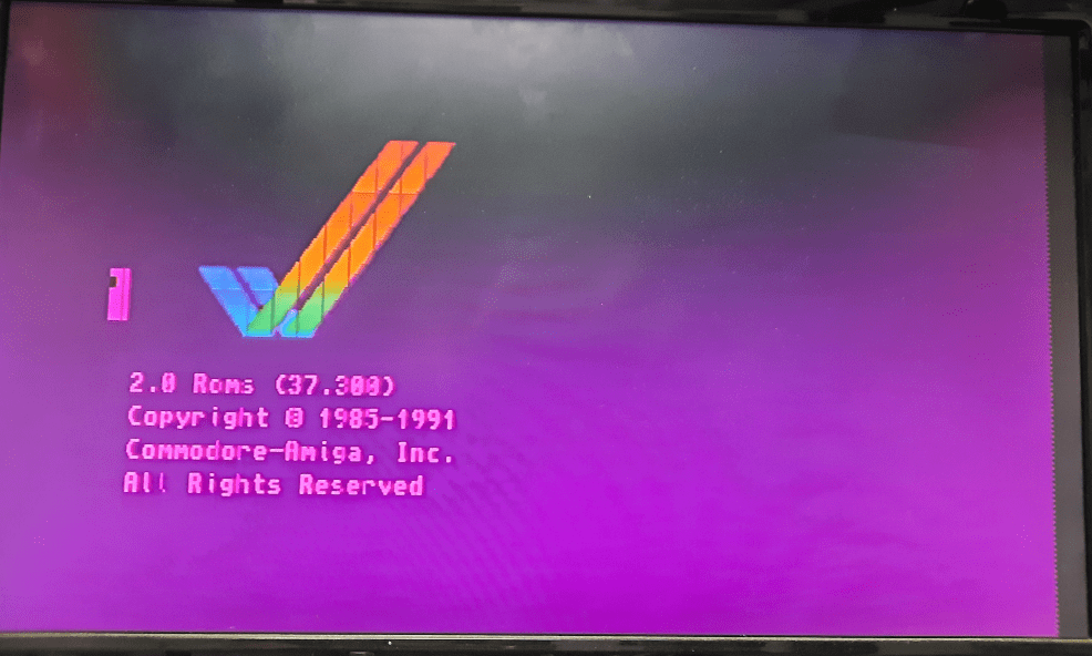
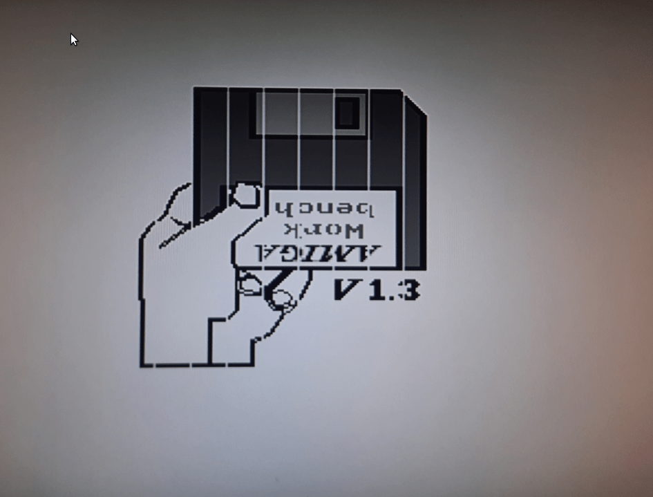
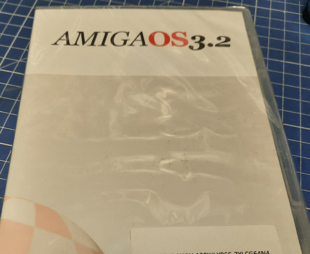
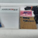
Meanwhile, Amiga OS 3.2 arrived! YAY! 😀
Co-Pro
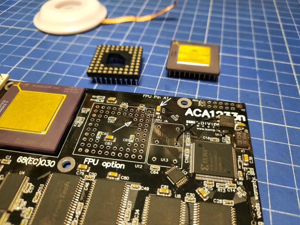
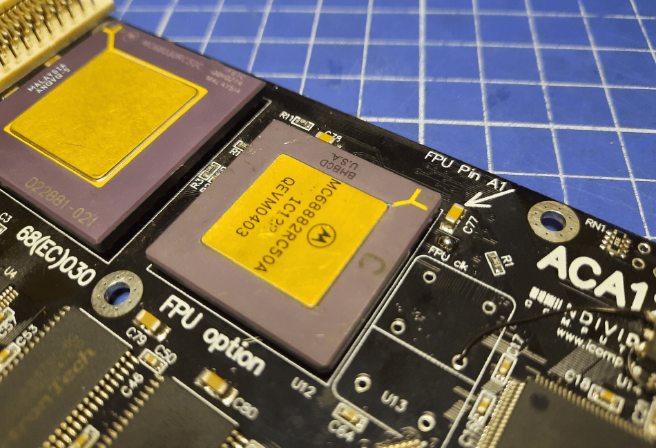
The next mod was all about fitting an FPU into ACA1233n. This is not a supported option and is not recommended by the Individual computers, but we were like, let’s just install it and see what happens lol 😀 Typical YOLO move 😀
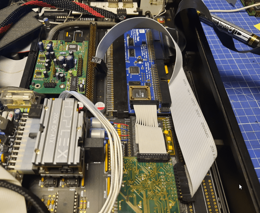
The major issue here was with space and clearance because Indivision ECS v3 is very close and right under ACA1233n.
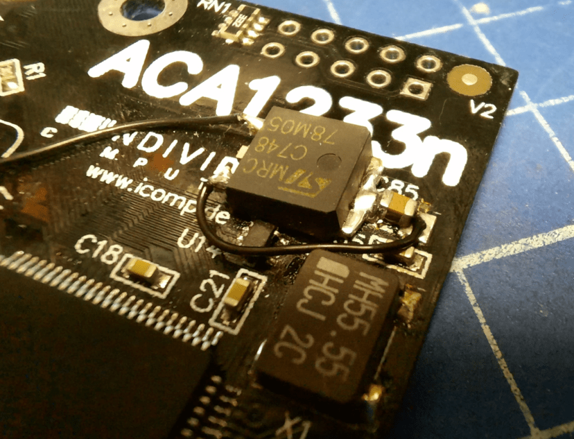
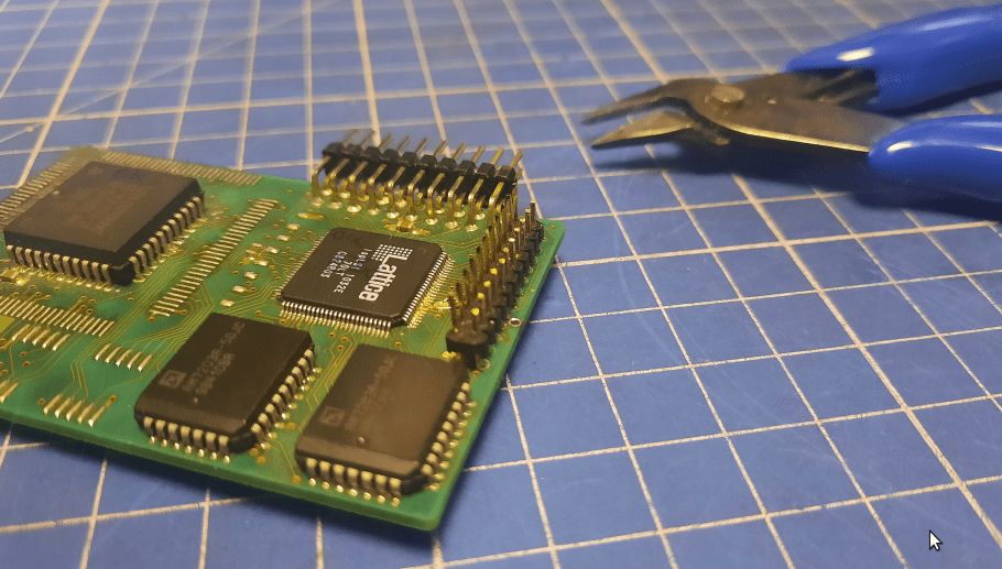
Originally, I wanted to put the MC68882 Co-Pro into a socket but because of lack of space, I had to solder it directly to the ACA card.
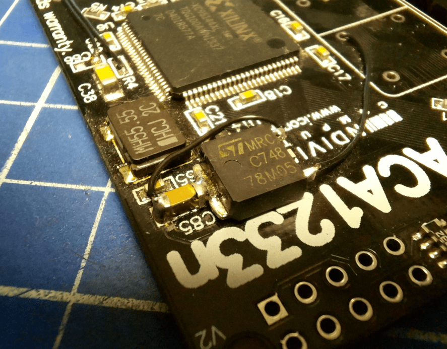
As usual in this project, it didn’t come without losses. This time it was a ceramic SMD capacitor that didn’t want to be tough enough lol 😀 I had to replace it. By the way, such a fault is a perfect example of why this project took so long. It tookYouagnose and find what causes weird issues. Basically, you see a single pic below, but it took me a few days to find it as it sometimes worked and sometimes did not – unstable. Just to be clear, I didn’t install that Vreg and wires, the original fix/hack is made by the manufacturer.
Clockport add-ons – The Melody 1200, Twister1200
This one is heavy. First of all, I was super scared to touch it because The Melody 1200 is a rather rare card and as we all know, there are always problems when connecting stuff through clockports.
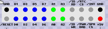
Here is some info about the clockport itself for those of you who are not familiar with it.
The major issue with clockports is that you have to be super careful and connect it properly because if you mess up things here, it will result in burnt cards and sometimes magic blue smoke 😀
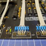
The best way to test the wire orientation is to look for two GNDs in a row and connect add-ons by matching GNDs.
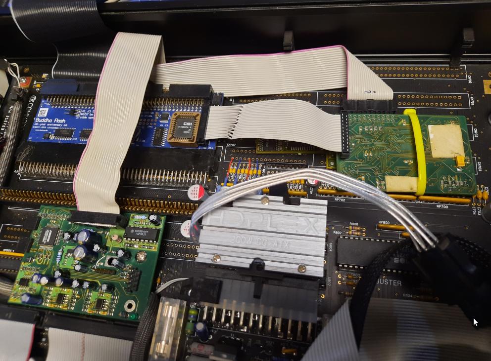
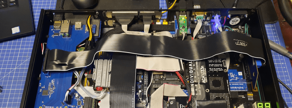
In this project, we have three separate clockports. One is served by ACA500+, another is served by ACA1233n and the last one is served by BuddhaFlash. Here is the idea that Mr.Trinsic figured out.
ACA500+ will communicate with HyperCOM3+. ACA1233N takes care of RapidRoad USB. BuddhaFlash will sort out communication with The Melody 1200 along with Twister 1200 as these two work in tandem.
I’ll spare you tons of wiring combination pics but honestly, it took a while to figure this out.
GND matching pic 😀
It also required ordering and making custom clockport wires such as the one below.
The Melody1200 hax
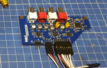
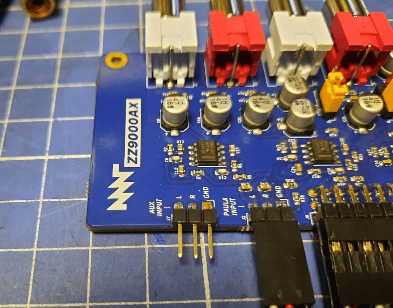
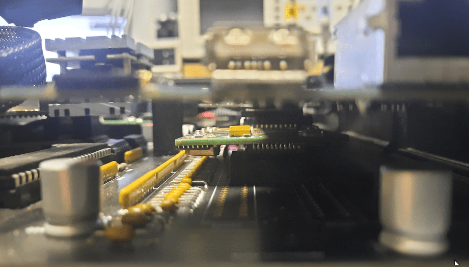
To complicate it even further, Mr.Trinsic acquired a ZZ9000AX module for ZZ9k which has an AUX line.
He’d decided that output from The Melody 1200 will go straight to the AUX line of the ZZ9000AX module.
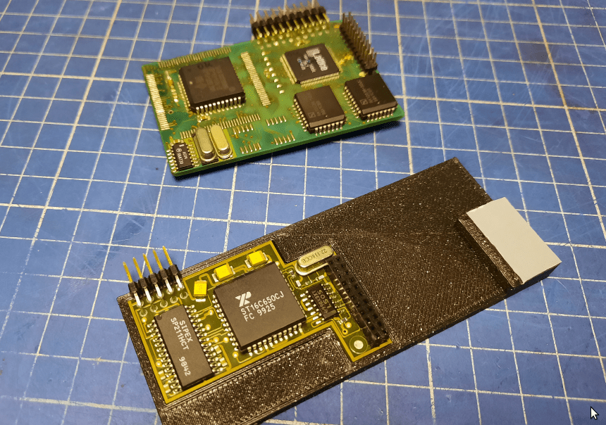
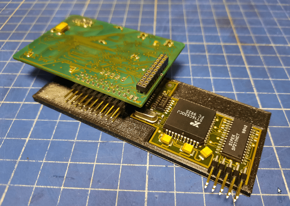
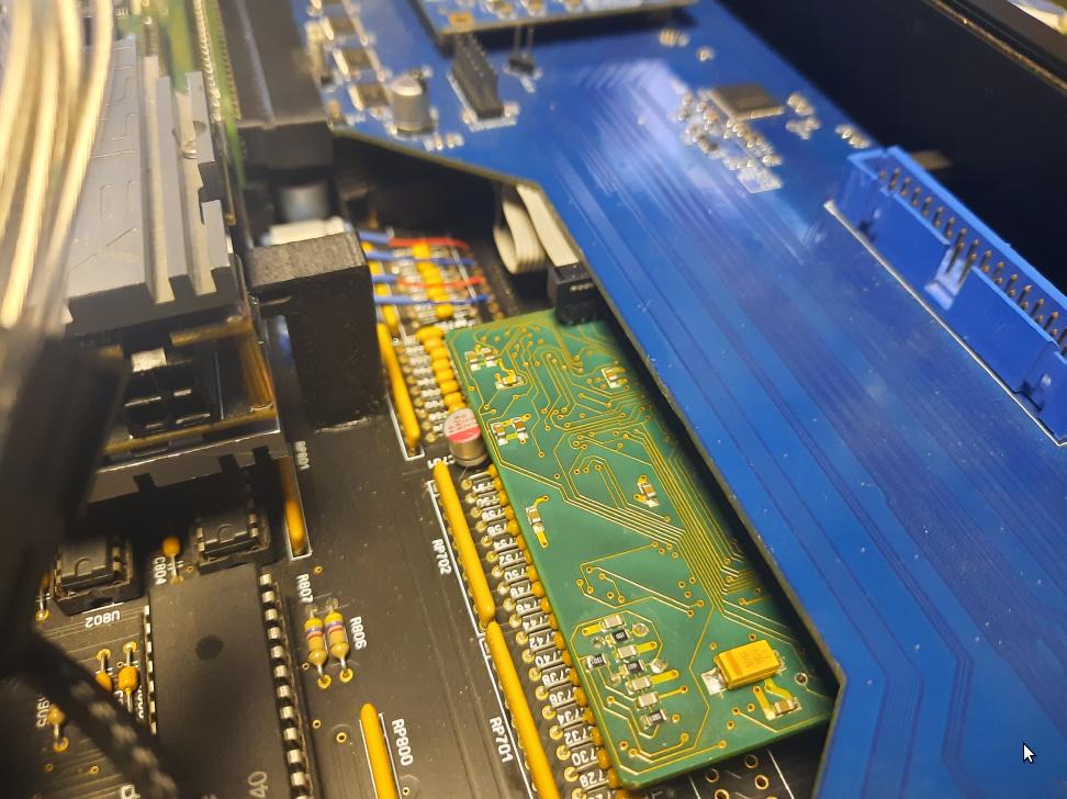
The Melody 1200 card consists of two parts connected through a ribbon wire. My idea (after days of thinking) was to put one part of it under ZZ9000 and the second part between the Zorro port and CPU slot.
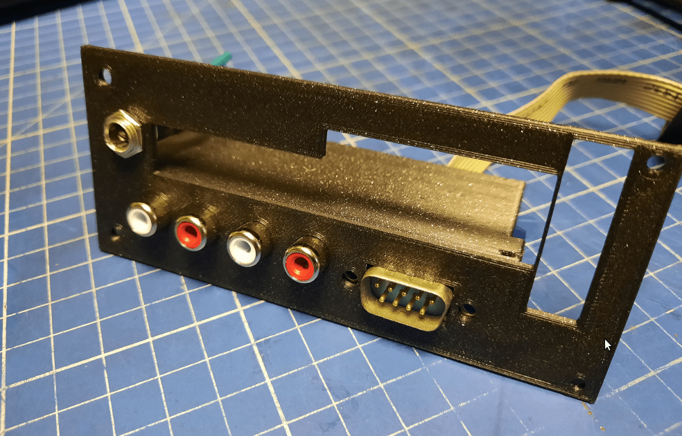
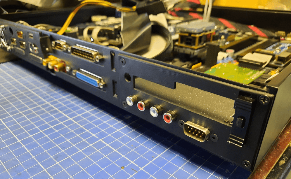
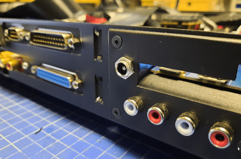
Also, there is a space limit for the back panel so I had to address it too. There are a few ports to put on the back panel – ZZ9000, ZZ9000AX, Twister 1200, and The Melody 1200 ports. I also had to fit a PSU port there but that is for left for later 😉
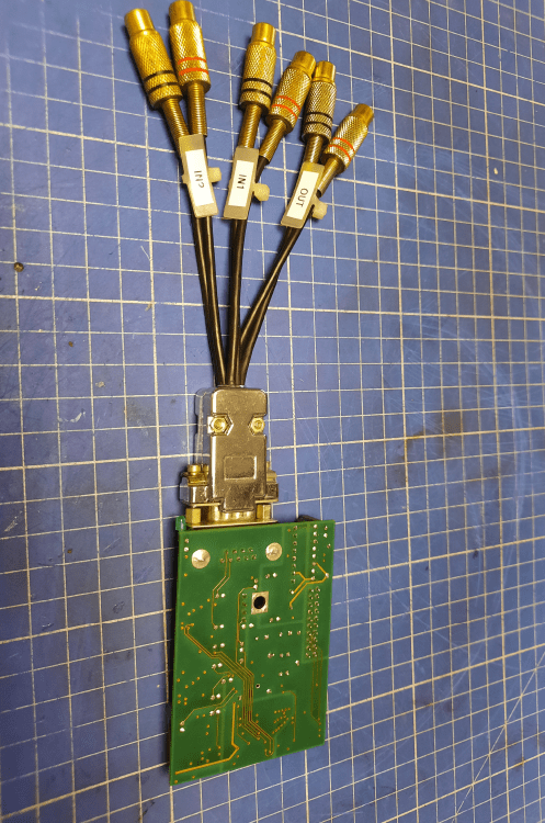
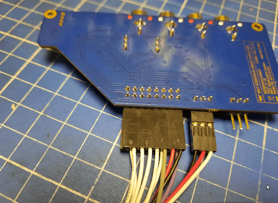
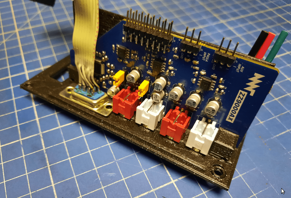
First, I had to desolder the DB9 socket from The Melody 1200 daughter board.
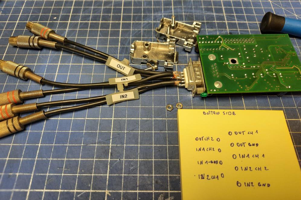
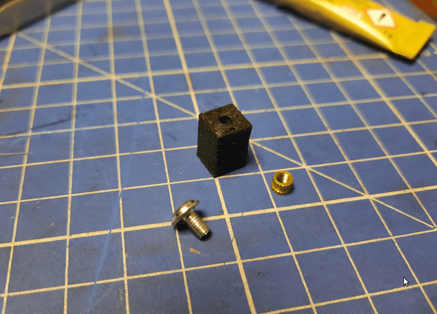
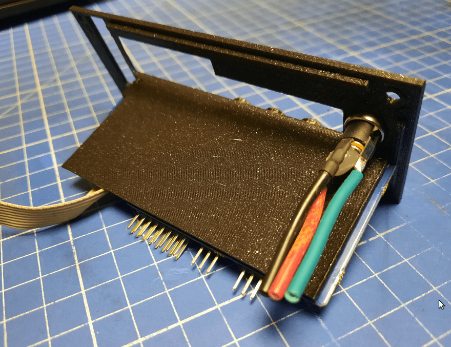
I then 3D printed some studs to hold this board in place and mounted it afterward.
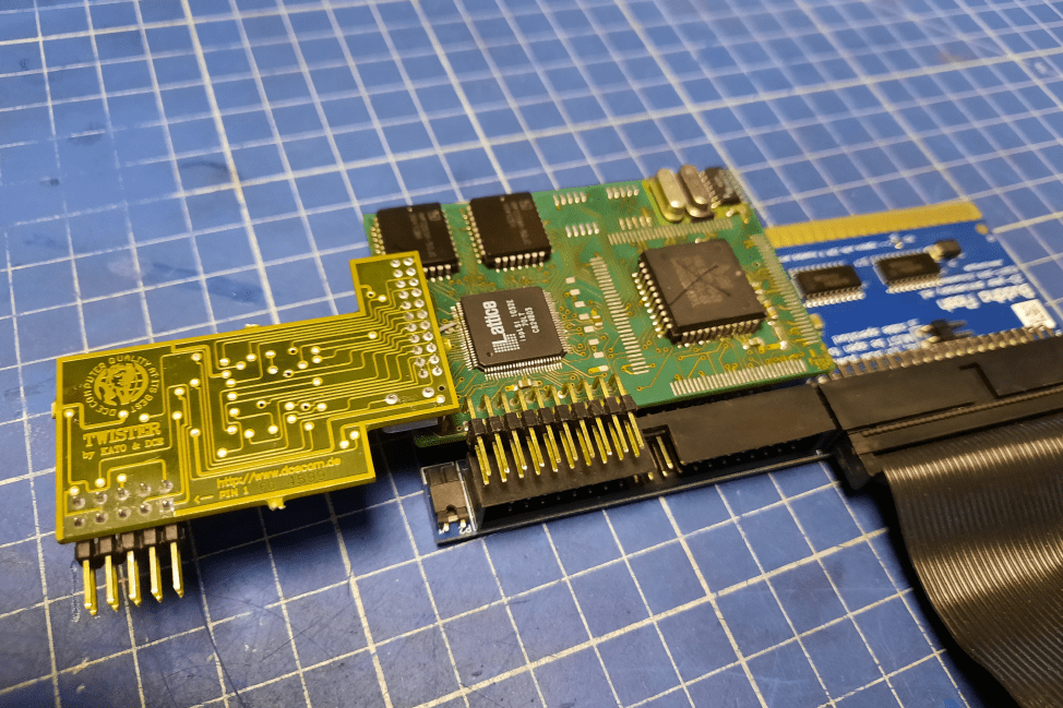
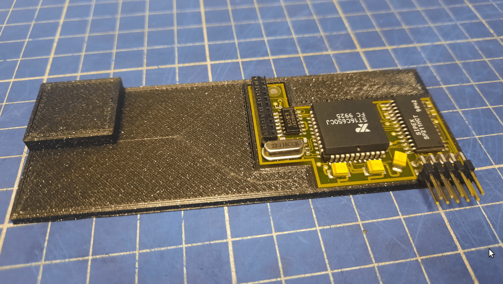
With the daughterboard fixed in place, I could start working on the main board and Twister1200 mounting bracket. It was 3D printed as usual. Here is how it looked.
I also made a custom-length ribbon wire to connect two boards.
Unfortunately, that wasn’t good enough and the whole set – Twister, Melody, and a bracket didn’t fit under ZZ9000.
I had to try harder 😀
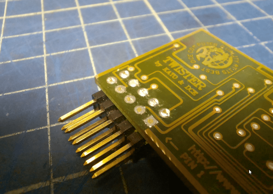
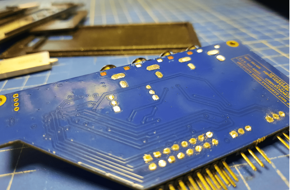
The first trick was to shorten the gold pins on the Melody1200 a bit.
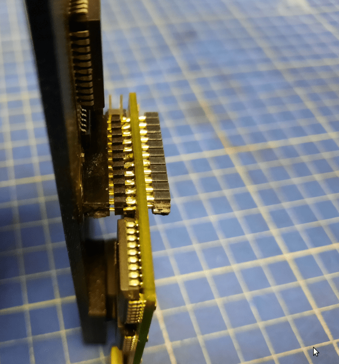
1mm of room saved 😀
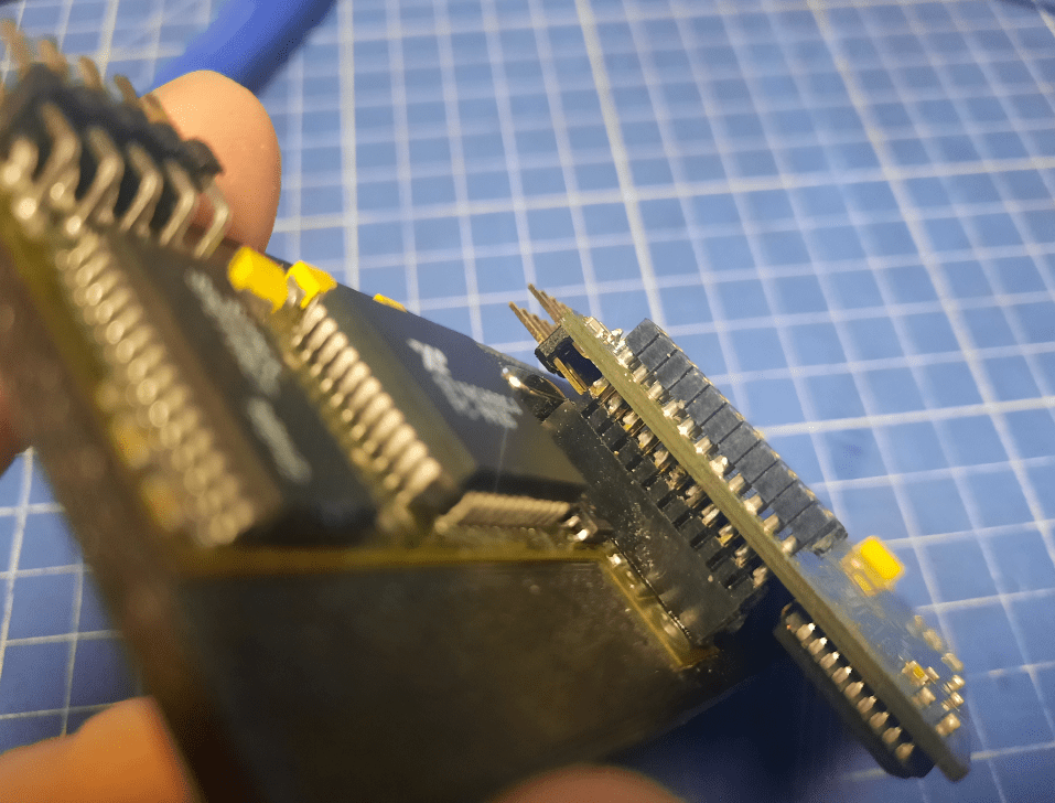
The other trick was to redesign a bracket and trim everything on the underside of Twister 1200. That saved at least two millimeters more.
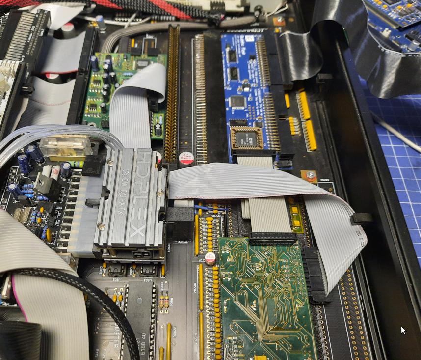
Now it finally fits under ZZ9000 without putting pressure on it! Success!!
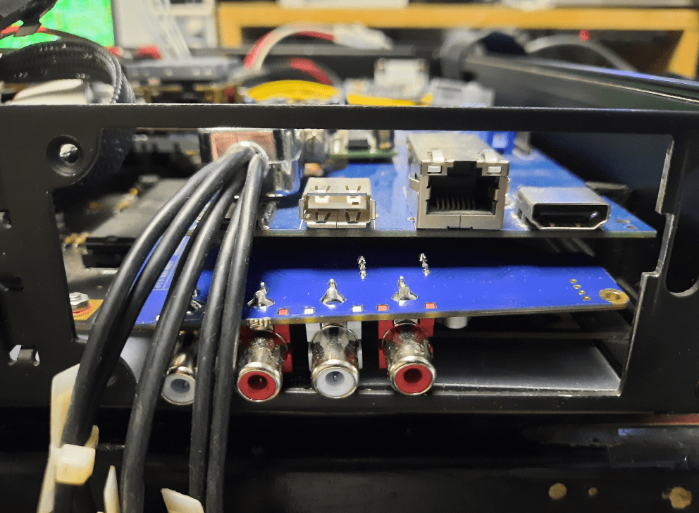
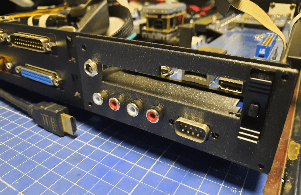
ZZ9000AX and the back panel
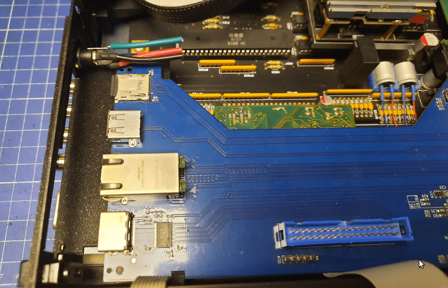
With the cards fixed, I could start working on the last piece of the back panel.
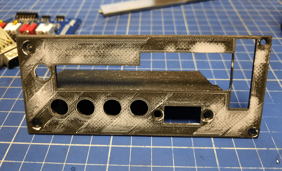
As usual, I had to go through several iterations.
ZZ9000AX module also had to be trimmed to fit the panel. Here is how the process looked.
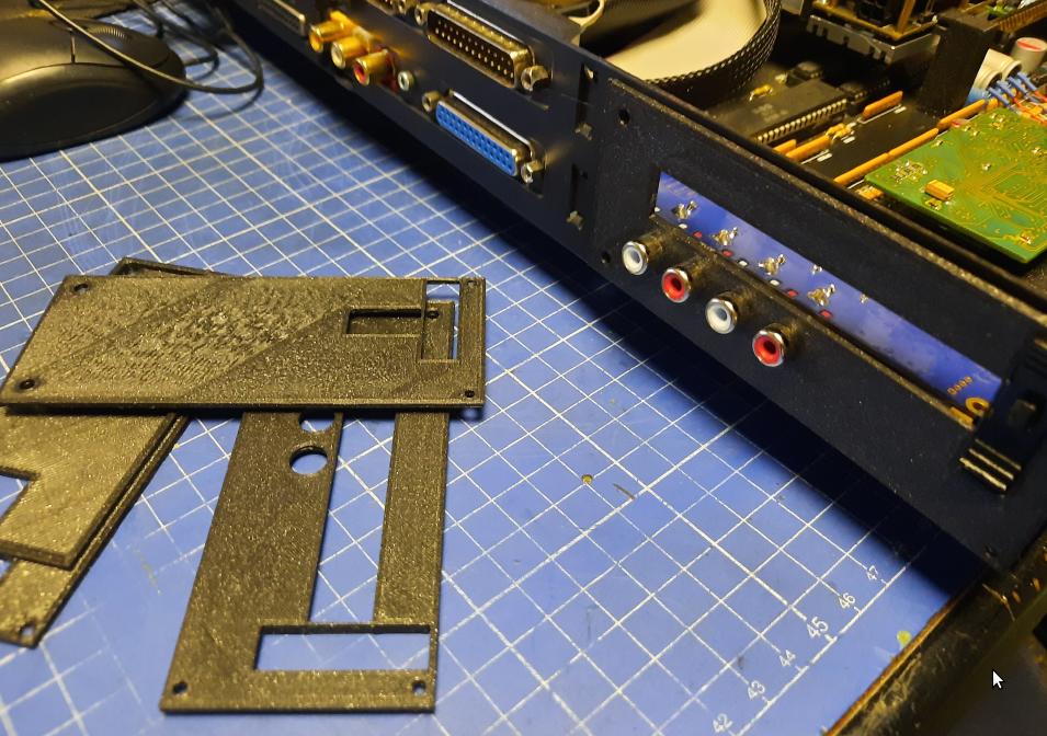
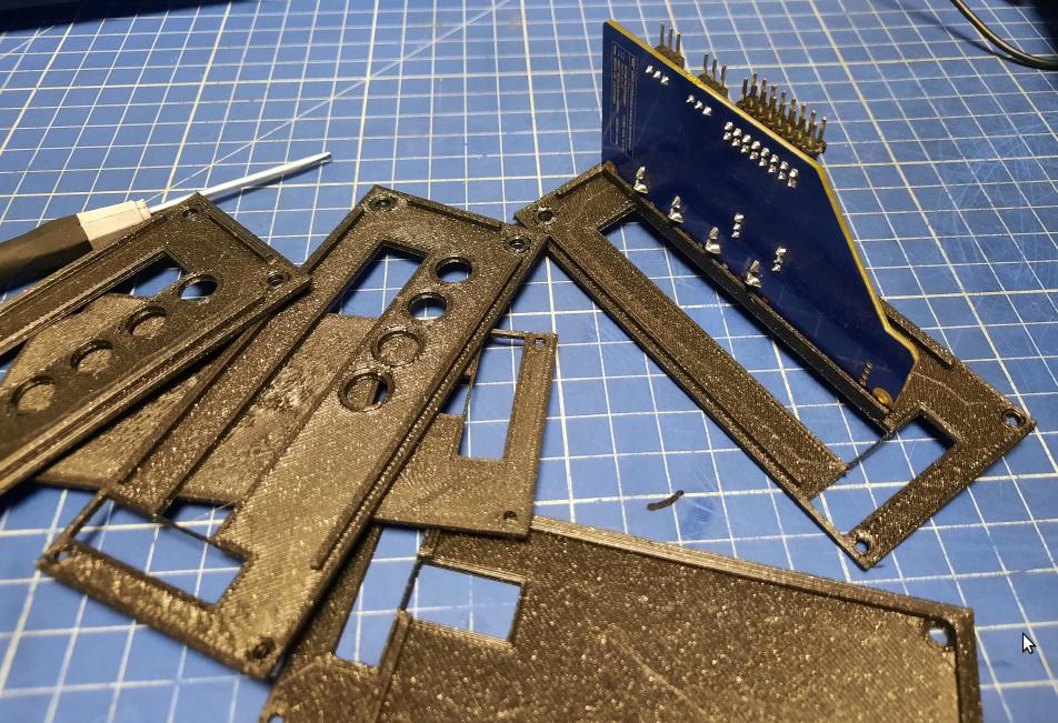
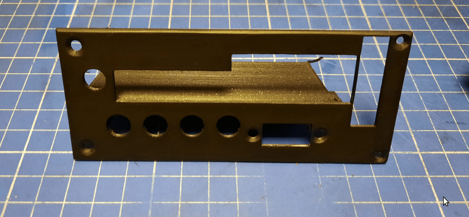
The final printout had to be post-processed with a putty layer and spray paint to match the rest of the back panels.
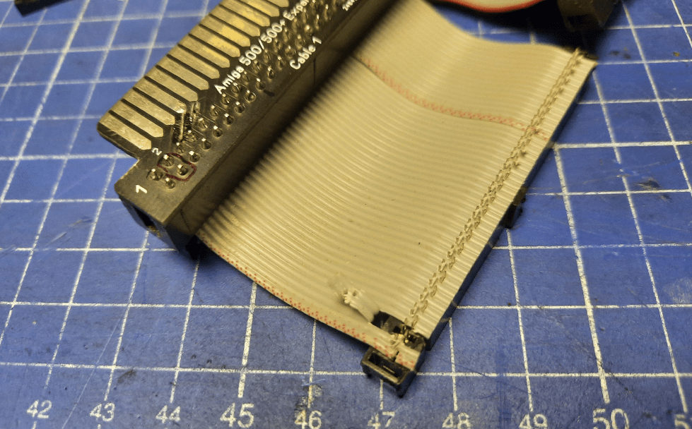
Custom clockport wire
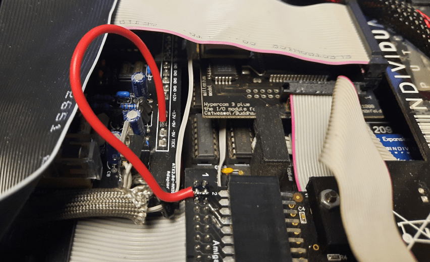
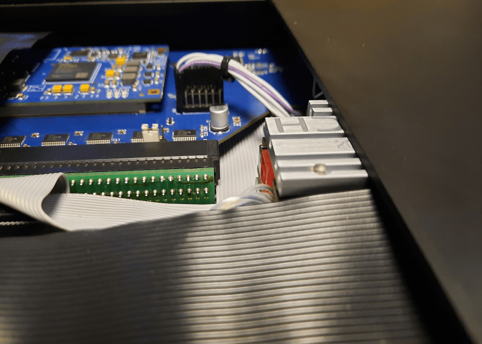
One of the issues that had to be addressed, was a custom clockport wire that goes from ACA500+ to HyperCOM3+.
I needed to make it a bit longer and twisted 😉
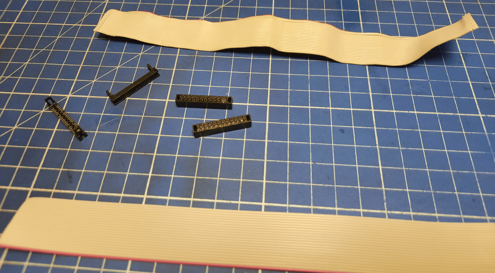
That was a bit time-consuming process. I didn’t have brand new IDC plugs but I had a wire that was burnt and couldn’t be used anyway. I’ve disassembled it and re-used its connectors.
ZZ9000 adapter wire
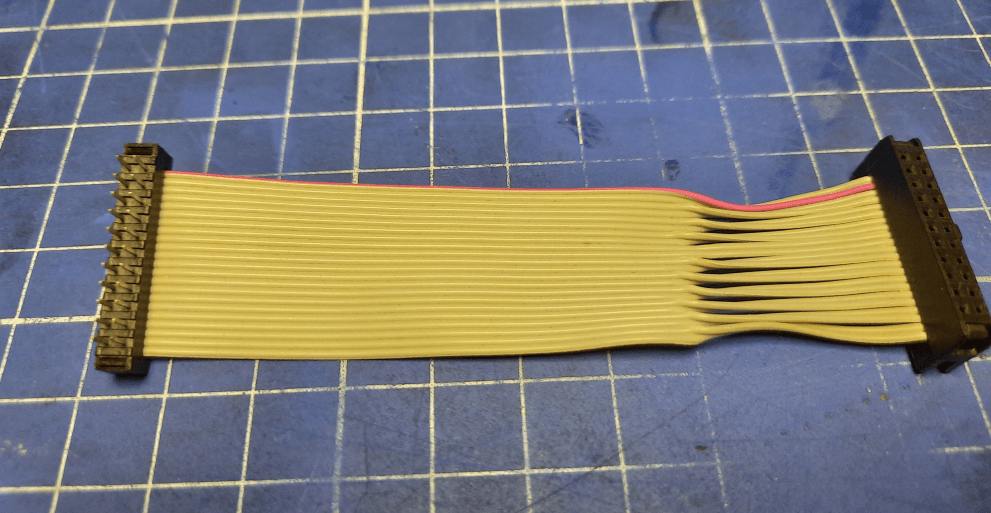
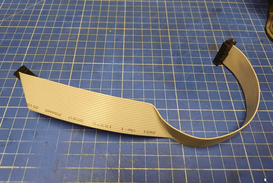
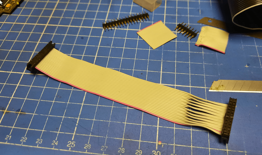
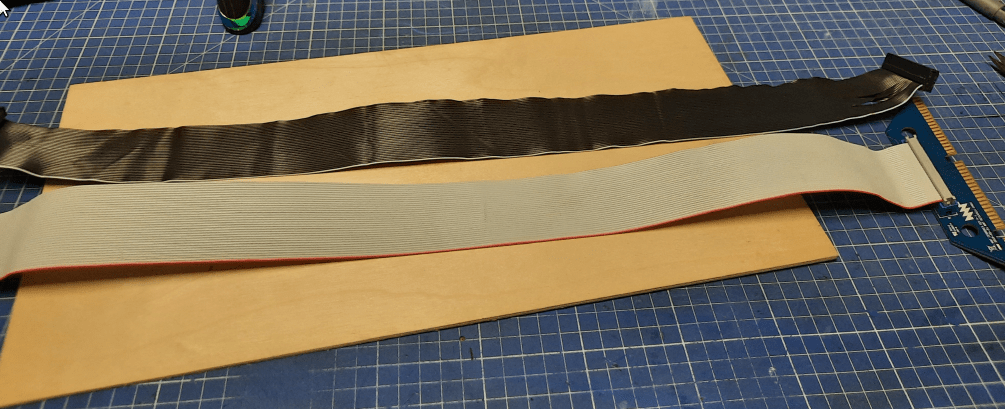
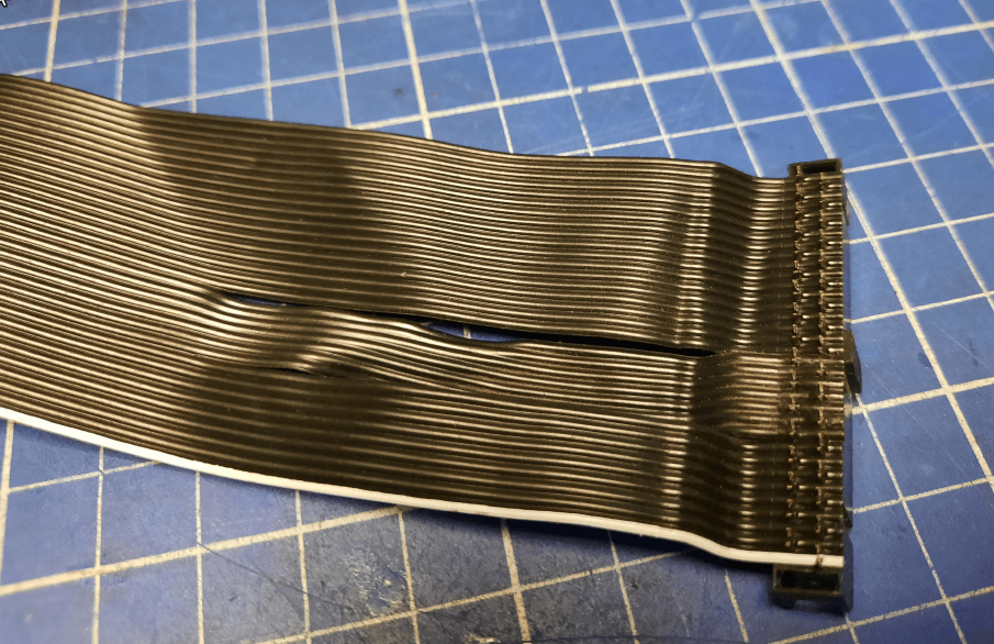
The next piece that required attention was a ribbon wire connecting ZZ9000 and its adapter for A2000.
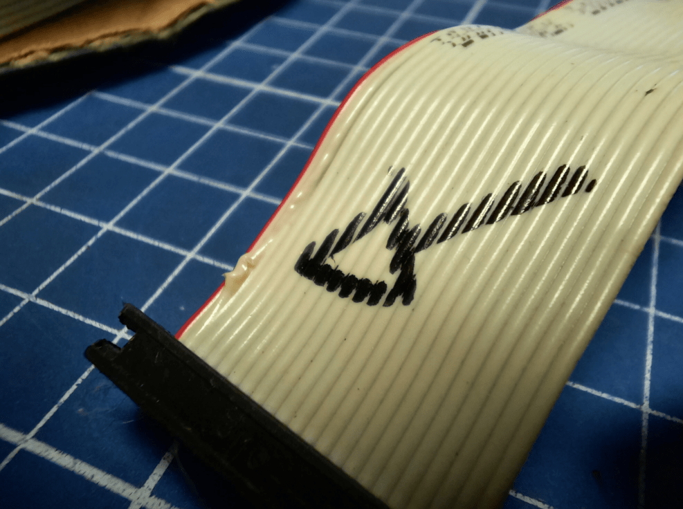
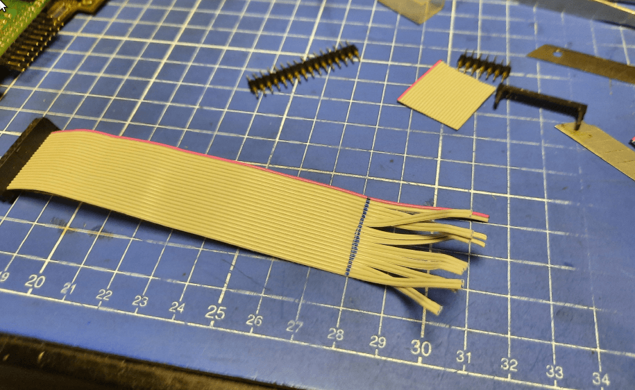
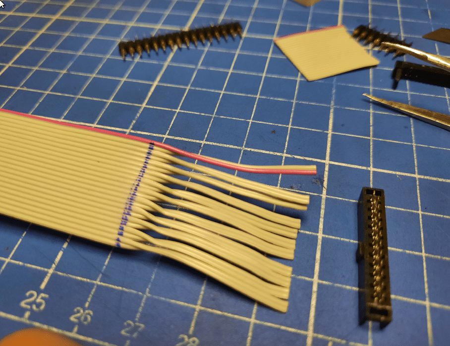
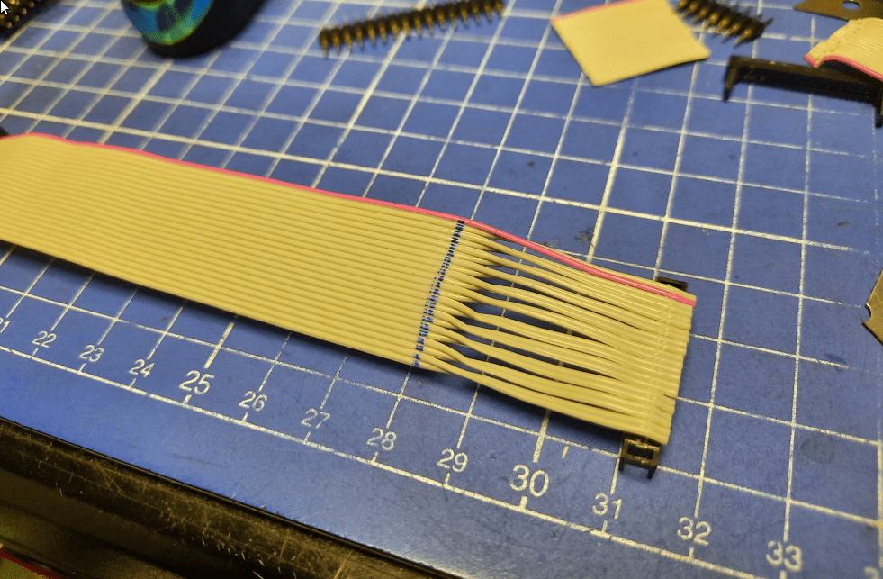
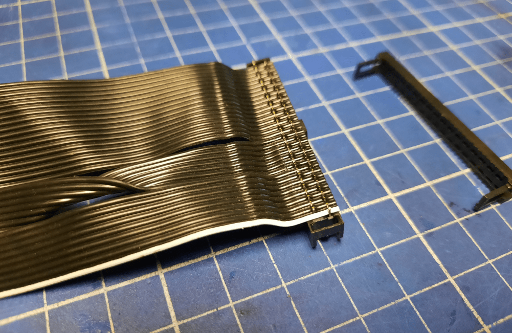
This is the usual 34PIN wire but I needed a black one so it matched the rest of the build. I’ve decided to use a floppy wire that I had but this one needed untwisting for a change 😉
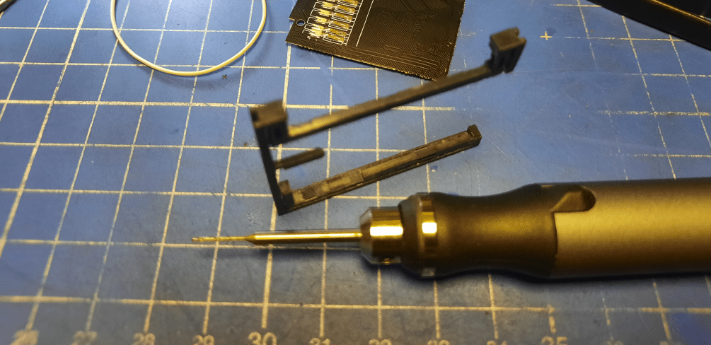
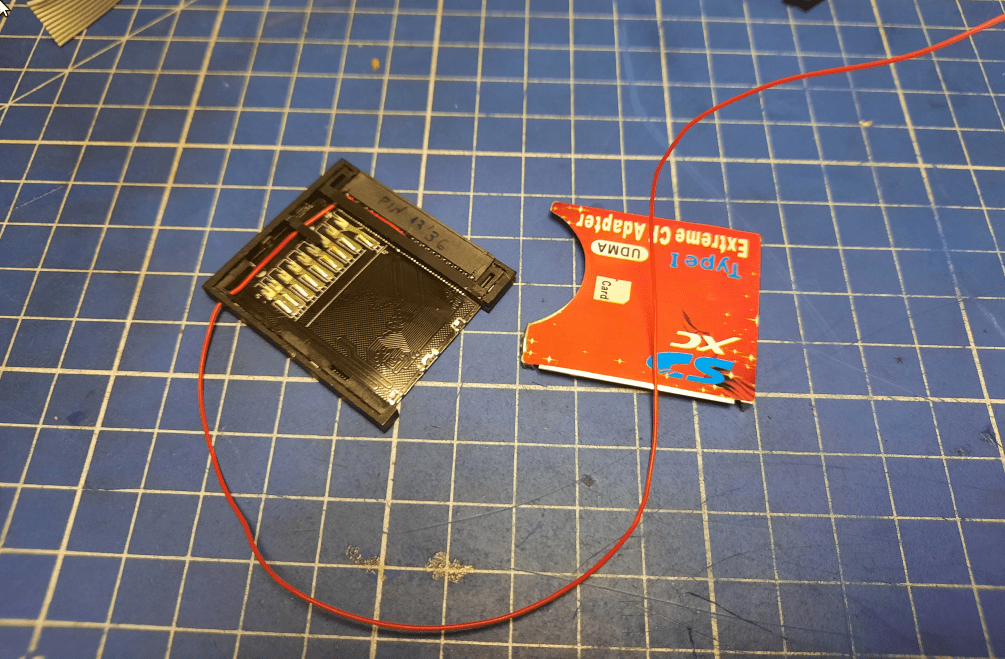
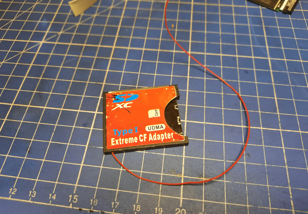
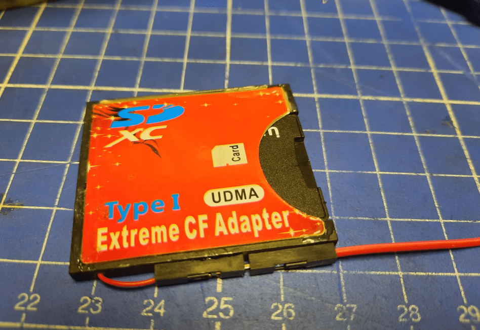
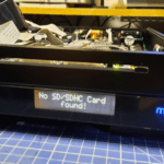
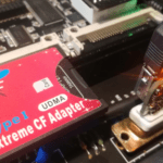
CF2SD adapter and ACA500+ voltage drops
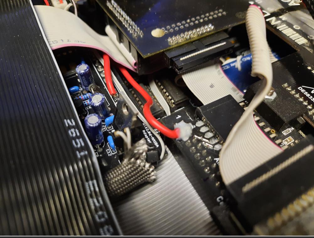
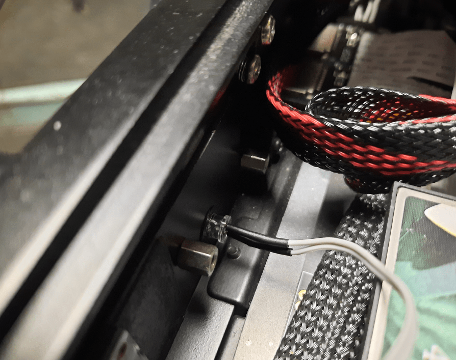
While running various tests, I’ve noticed that sometimes CF2IDE adapter card doesn’t always work. Especially when using a microSD extender. It took me a long while to figure this one out and it was a part of a larger problem … ACA500+ voltage drops. Because a lot of devices are connected to ACA500+, the voltage of a 5V rail drops to 4.2V. It is not a problem of the PSU itself as it is strong enough to supply a lot of juice, however, there is a significant voltage drop on a wire that connects the CPU slot and ACA adapter. The solution to it is not a nice looking one but it had to be done to keep the system stable. I connected a 5V rail directly to PSU via a single and thick wire and secured it with UV resin.
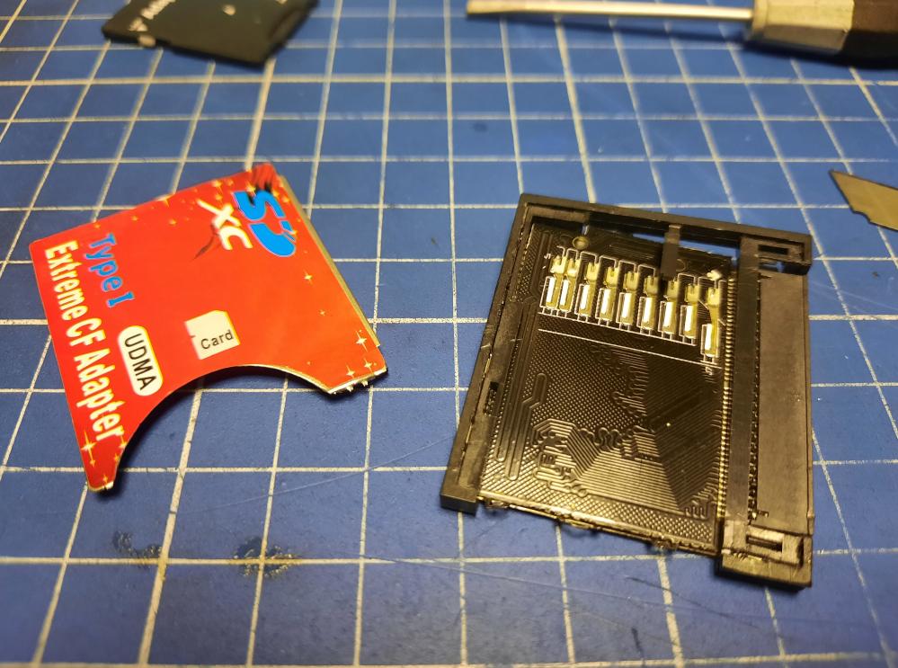
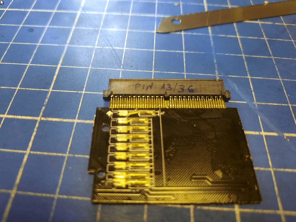
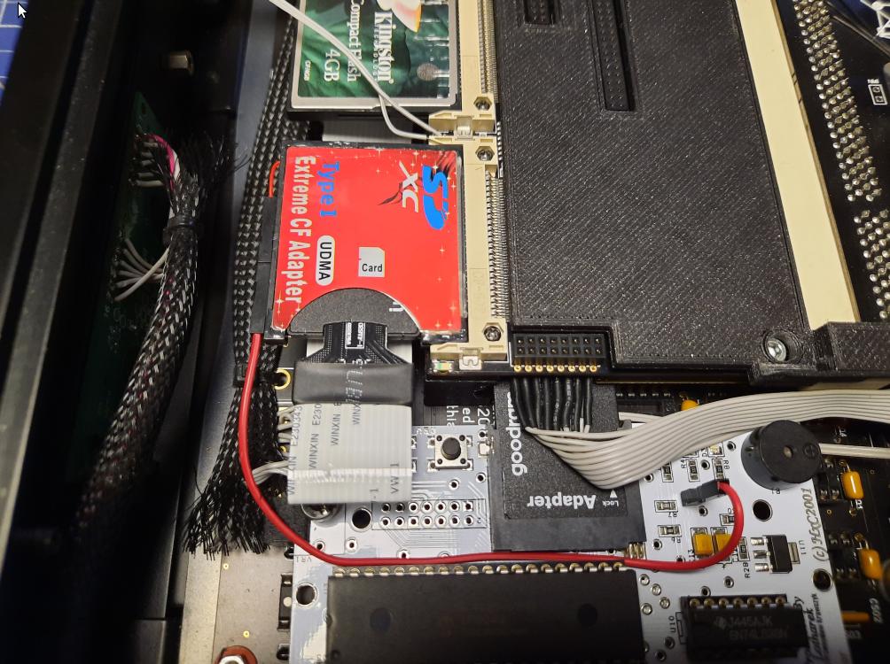
The above helped a lot with stability but still didn’t fix one last issue with the CF2SD adapter.
I had to disassemble it and wire the 3.3V rail to a nearby HxC module. A bit of precise work for a change 😉
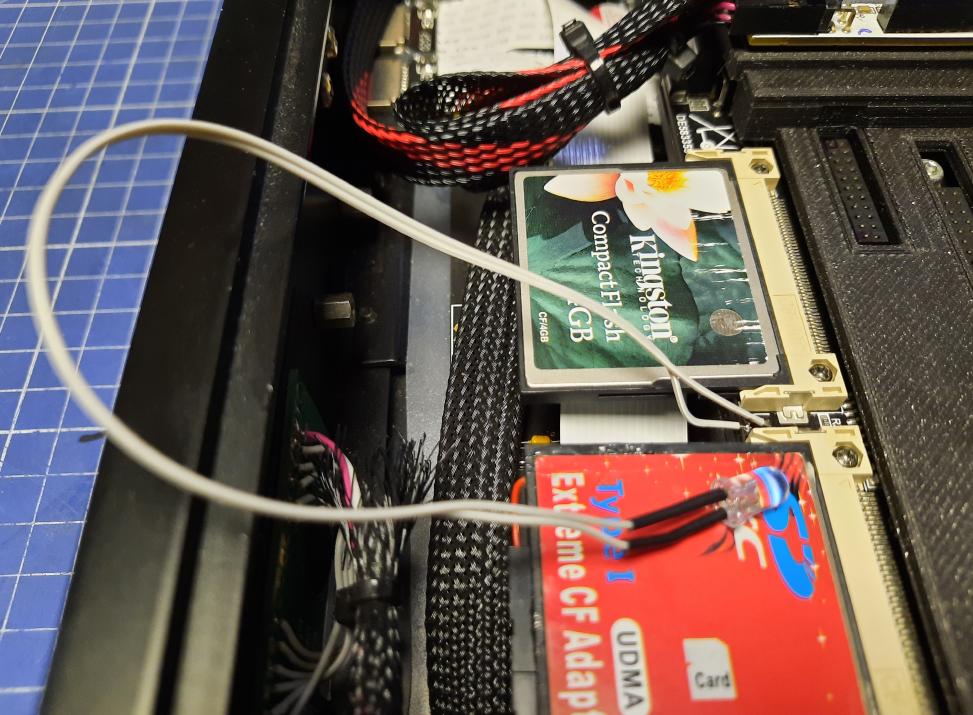
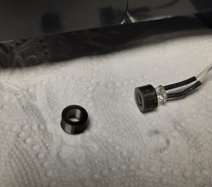
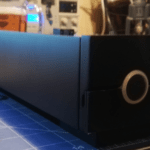
ACA500+ “HDD” LED
Mr. Trinsic wanted to have an LED indicator of an “HDD”. Obviously, in this case, it is an SD card. However, I’ve managed to achieve this goal by desoldering the original SMD-mounted LED from ACA500+ and installing a 5mm one on a wire and inserted into a 3D-printed round bracket.
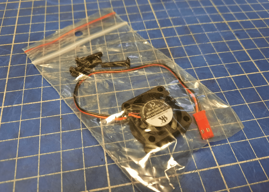
PSU fan
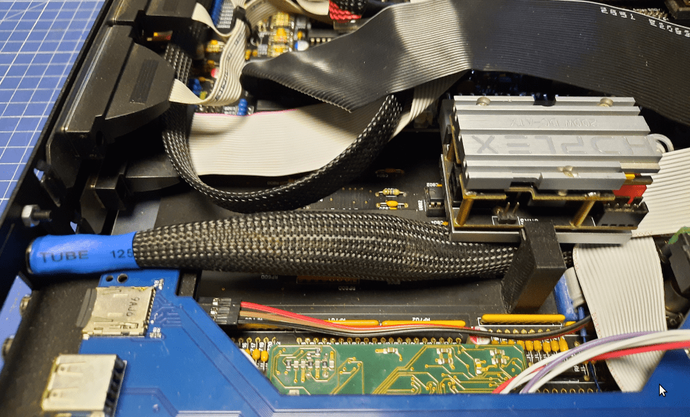
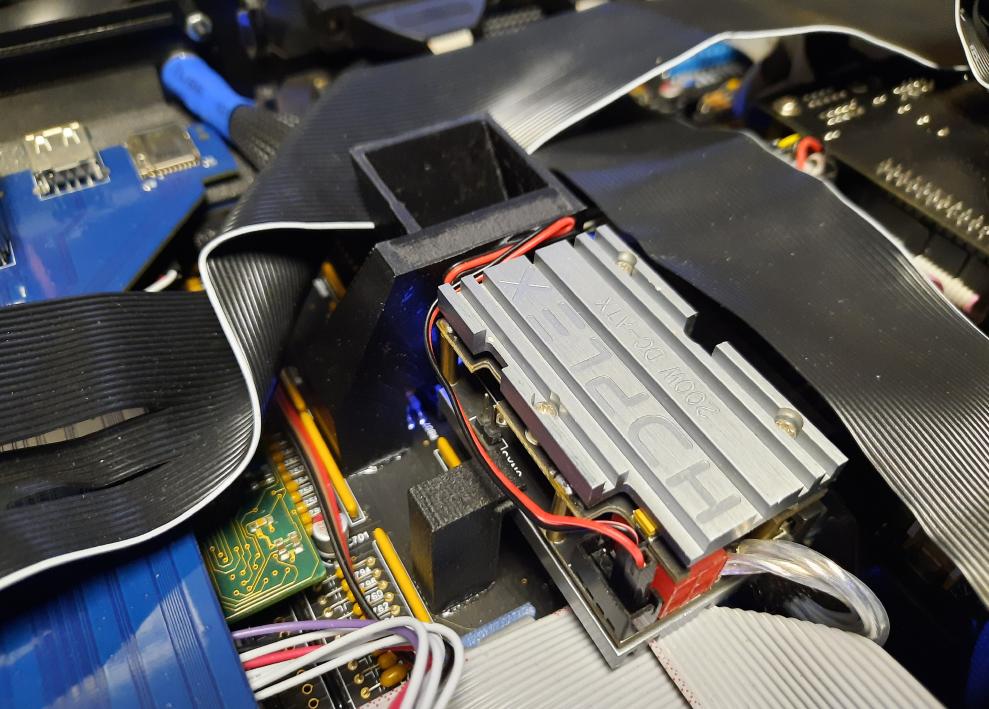
The height of all internal PSU studs and stand-offs were designed to maximize heat dissipation so the aluminum lid cover would touch the HDPLEX PSU heatsink.
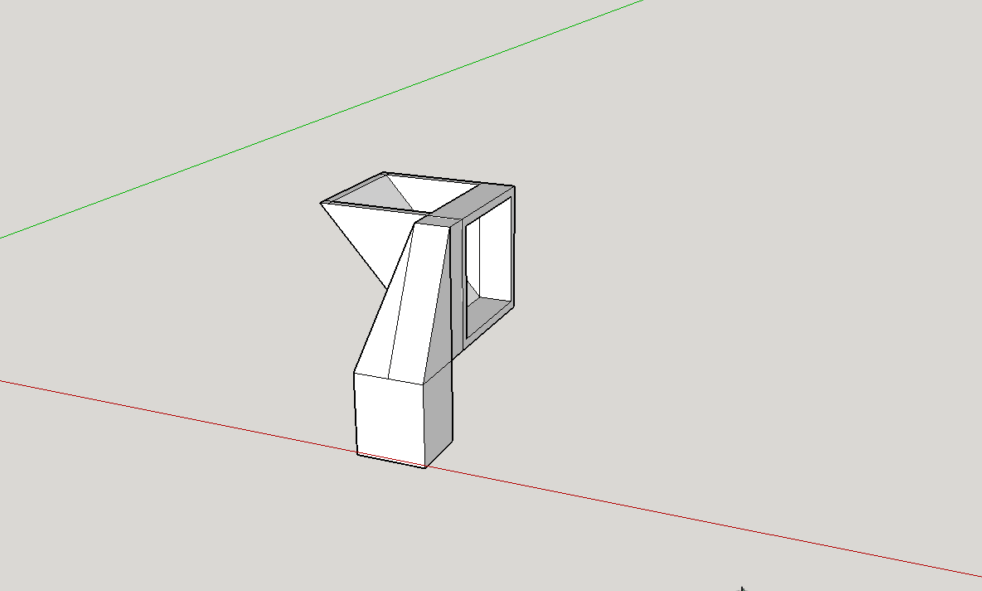
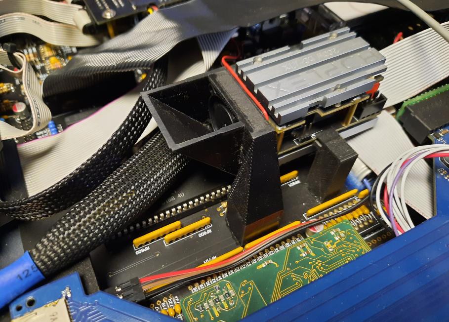
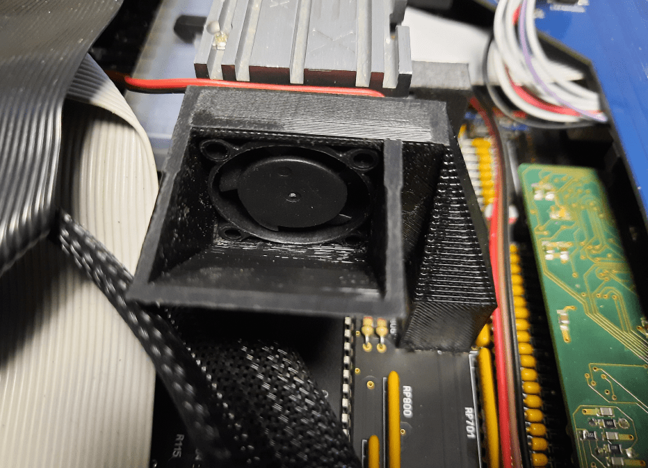
However, there is also a bottom heatsink that has to be cooled. I’ve decided to add another fan to the system. Yes, it will be louder a bit but will keep the PSU cooled more evenly. A 3D model was designed and 3D printed.
Re-wired…
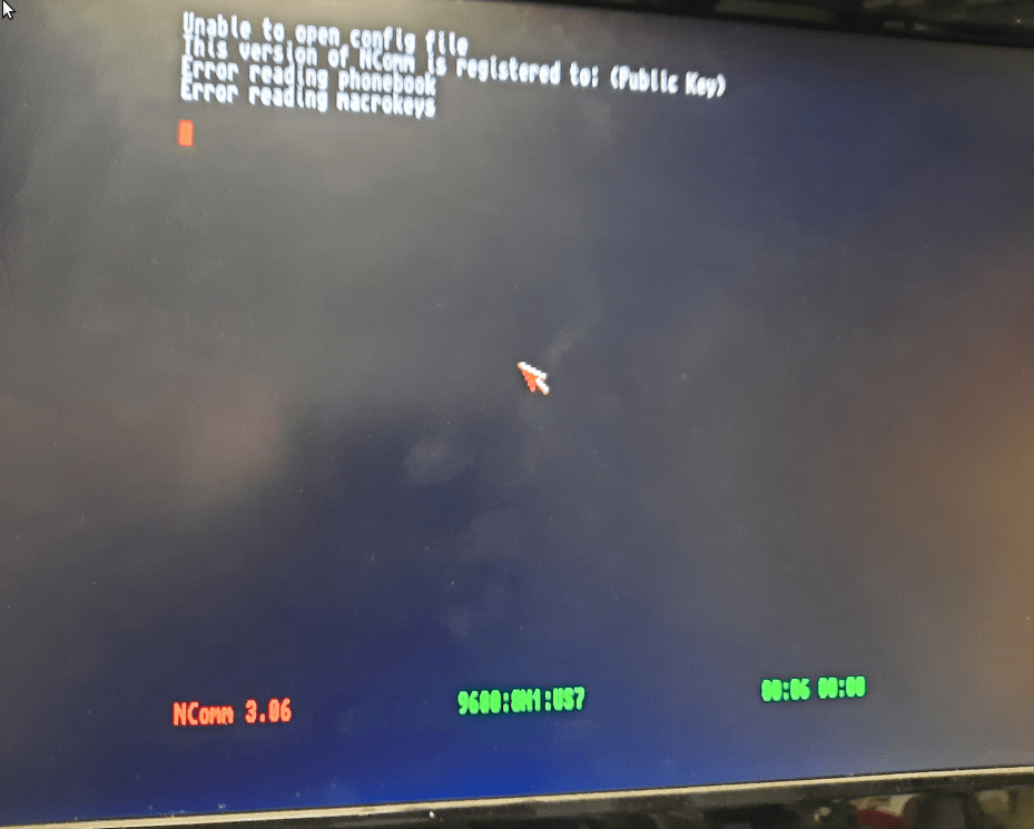
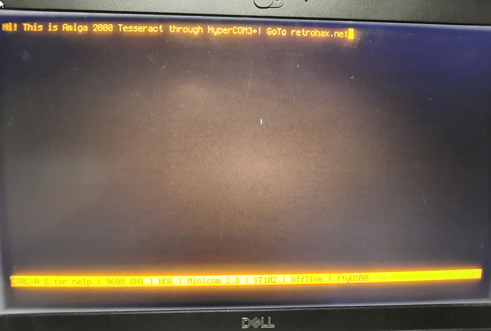
HyperCOM3+ final tests
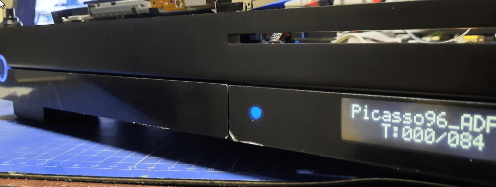
I’ve run some final tests with a custom clockport wire and after fixing voltage drops. I’ve run tests using an RS232 to USB adapter – Proflic. This time, I had no issues writing msgs from Amiga to my Linux box terminal that was connected on the other end.

That’s it
… for now. There is one more final post remaining to be written. I will write it soon as an addendum to the whole project as I didn’t want to extend this already lengthy post.
Outro
If you want to get the retro gear I am manufacturing or hardware modules, please visit shop -> https://retrohax.net/shop/
Please support my work by commenting here and on our Facebook or Twitter pages.
once this custom Amiga is done what plans for other custom Amigas?
It is actually done already 😀 I just need to write a final post about it.
We had some issues with shipping company and it will be covered in that post. The rest is up to MrTrinsic.
What an amazing masterpiece of hardware.
I started with the software-installs, and of course things don’t work out straight.
But once you figuered out everything, this is a wonder to behold!
Great to hear that sir! 🙂
Wow that was a hell of a trip there you got, amazing how many obstacles to solve.
Thank you sir 😉
Nice. But is it still Amiga? 😛
It is! 🙂
It absolutely is!
Check sites such as the Bog Book of Amiga Hardware or Amiga.resource.cx about even classial expansions. Accelerators with a 68030 @ 50 are nothing special. GFX cards are nothing special. Sound cards either. The Amiga 200 was from the beginning an absolutly robust workhorse.
The specific expeansions such as zz9000 or the ACA1233n are newer designs but are not really special. The ZZ9000 runs on P96, a gfx / RTG expansions from “back then”.
The package is special, yes.
Great to see artists at work :).