… or let’s start the longest and most complicated project so far
<Intro>
Ok, so this project …

</intro>
Links to all posts of this project:
Intro
This post or I should say a series of posts, is a result of a kinda (not yet, as it turns out :>) failed Amiga 1000 Phoenix upgrade project that I did write about some time ago.
It all looks like this is going to be my longest and most complicated project. It still has a work-in-progress status but I’ve decided to start writing about it because I keep on forgetting the details. I’ve already forgotten a lot, so time to refresh my memory and describe the idea behind the project, the job, and the details of it.
Codename: Tesseract
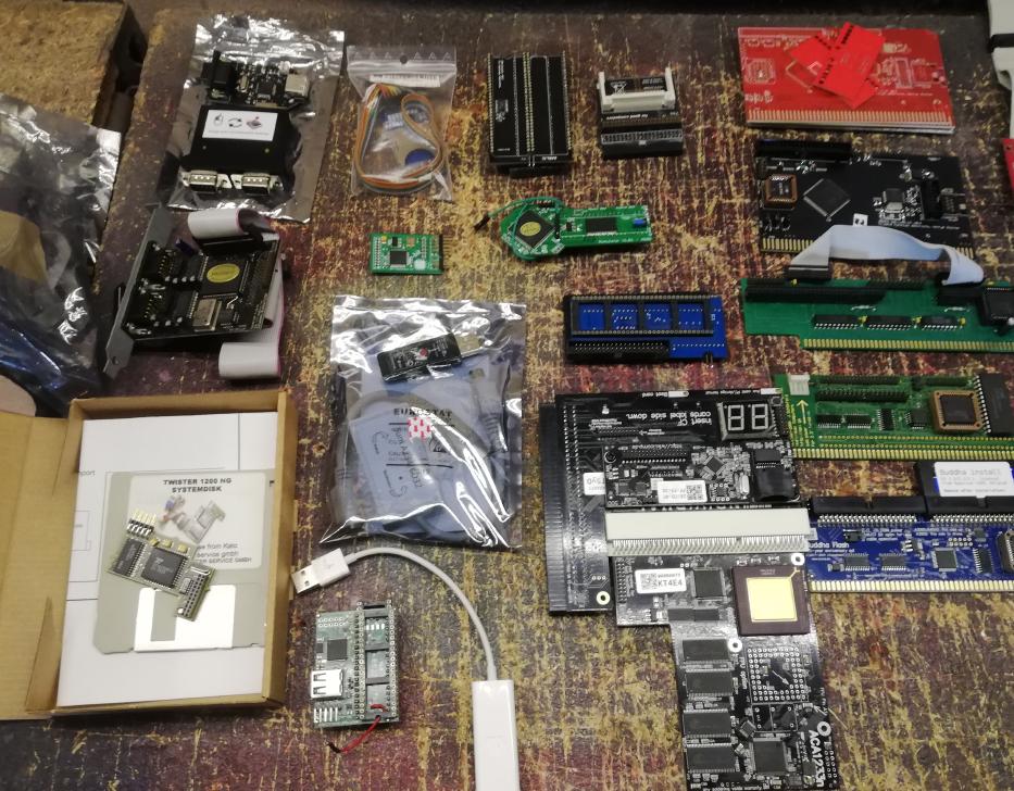
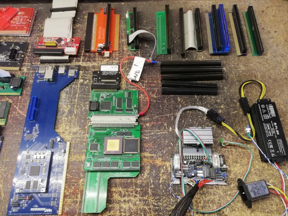
This post will be divided into at least four or maybe even five parts. I already have over 400 pics and we are far from the finish. This project evolves dynamically as there are a lot of problems that I have sorted out, so be prepared for twists and turns.
As I’ve described in A1K Pheonix’s post, MrTrinsic decided that we should try another route and by that he meant, to create a brand new custom Amiga 2000 from scratch, I mean like a TOTAL custom job!!!11!!eleven!!!!.
The brand new mobo, case, and tons of add-ons – brand new and old. At first, I didn’t realize how hard it might be but hey! this is why challenges are cool! am I right? So like Adrian says … Let’s get right to it!
The plan
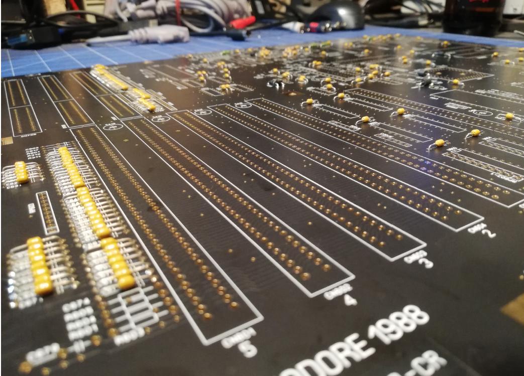
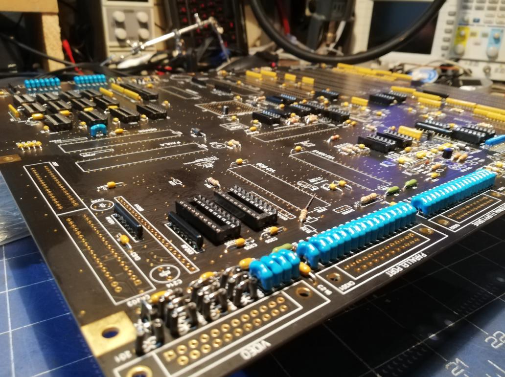
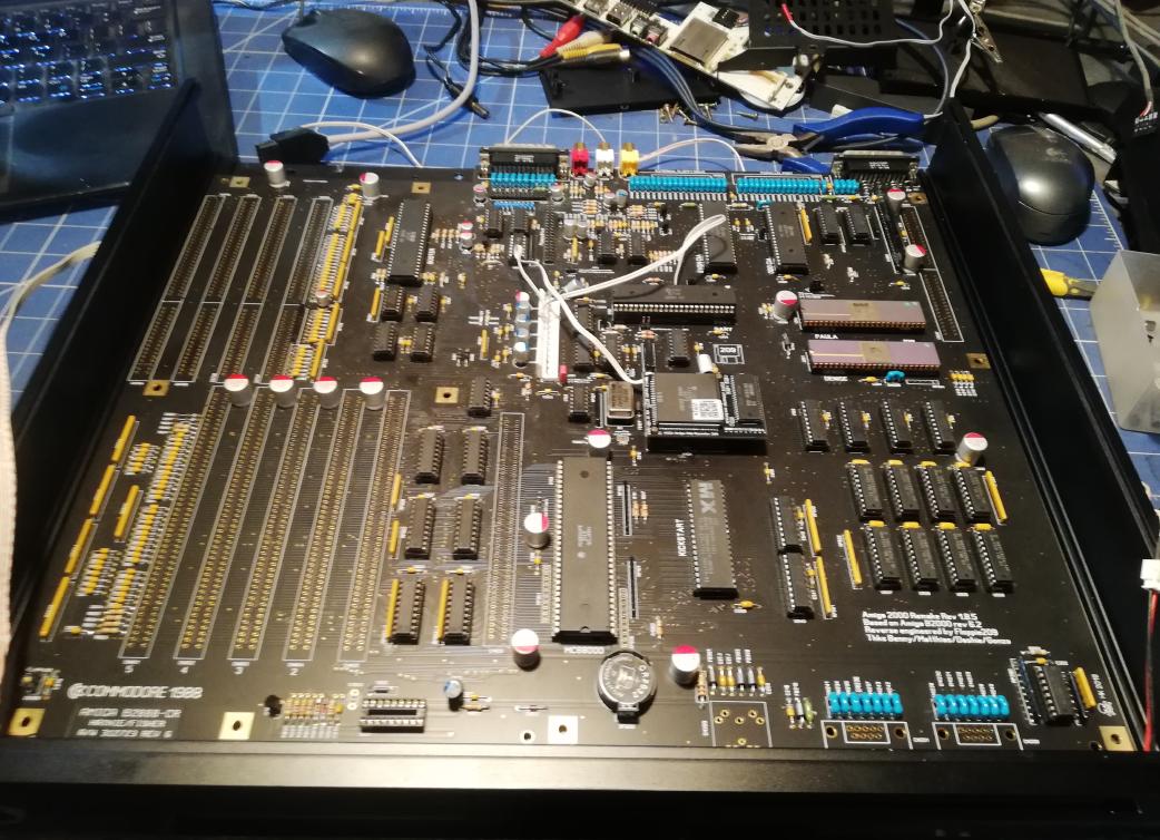
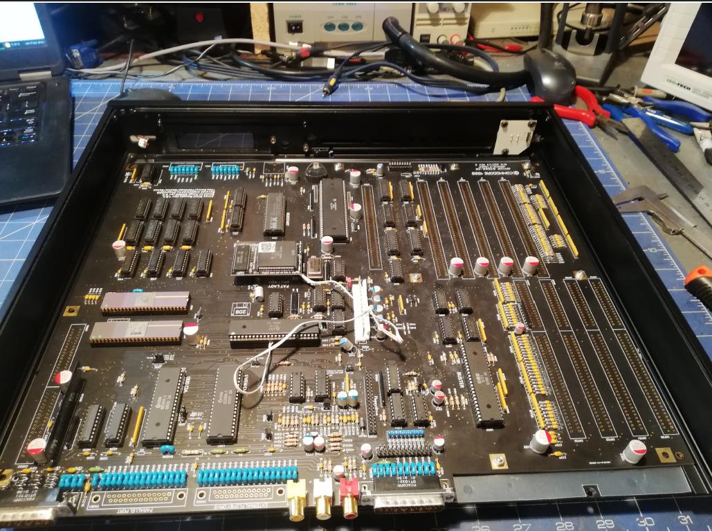
The plan was to make a fully working A2000 mobo from a scratch, meaning, to get a brand new PCB, solder it all up and make it work. That was my first task, which turned out to be quite easy but also time-consuming. As a bonus, it was also a very relaxing experience.
MrTrinsic RULEZ! He proactively searches and sends all gear directly to me which makes the whole job way easier so we are working on this project as a team and that saves a lot of time. Did I mention that this project is over a year and keeps on going lol?!
Let’s leave the case for now and focus on a motherboard build.
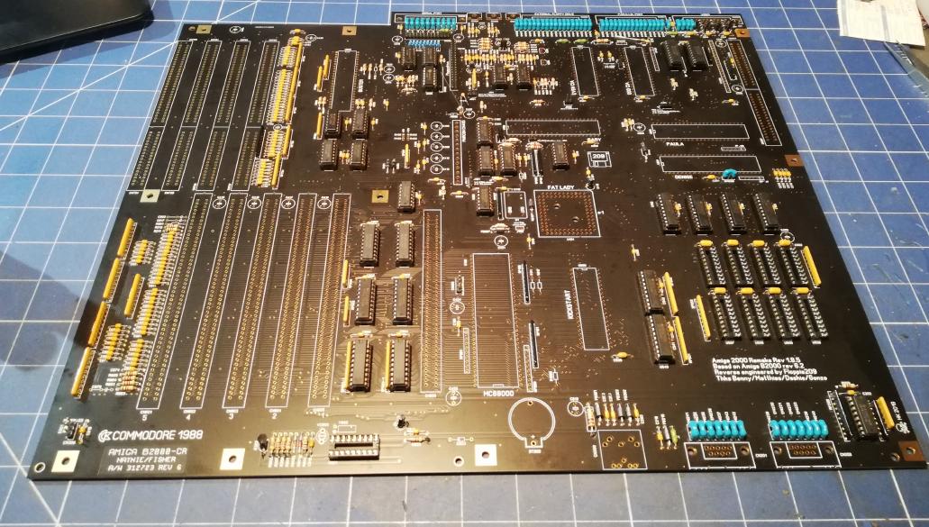
The marvelous MOBO
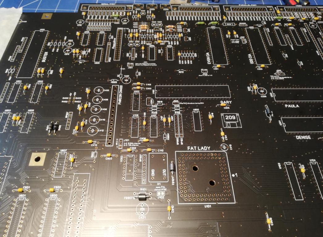
As I said, MrTrinsic sends/orders the majority of the gear needed for this project directly to me. I didn’t have to wait long for a brand new A2000 PCB to show at my doorstep.
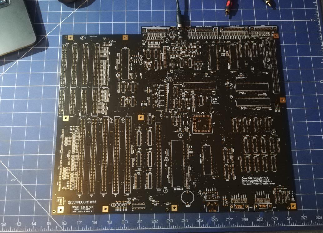
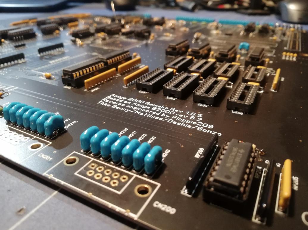
This is a PCB that was made brand new, based on an awesome rev-eng job done by Floppie209
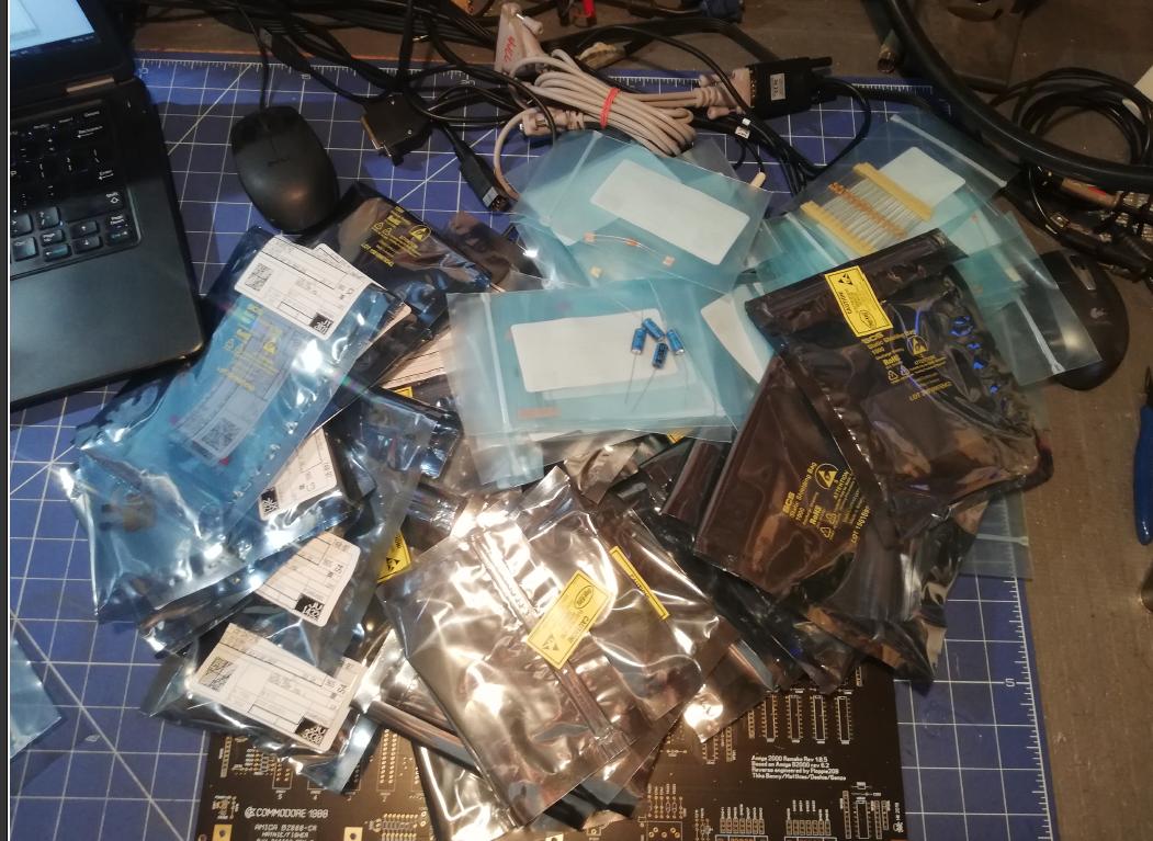
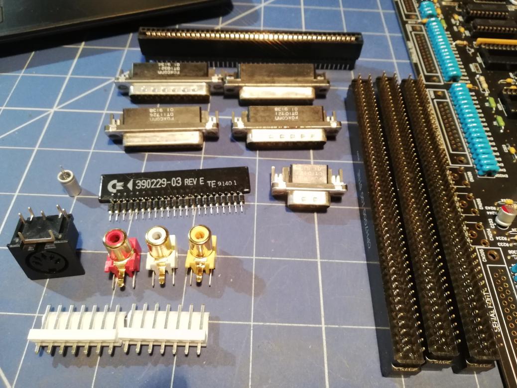
Shortly after receiving a PCB, I started to order parts like crazy. However, I did a mistake as I wanted to lower costs too much and I ordered parts from different shops. Now I know that I should’ve ordered all the parts from one, but big supplier as it reduces waiting time to a minimum.
Anyways, candies started to show up.
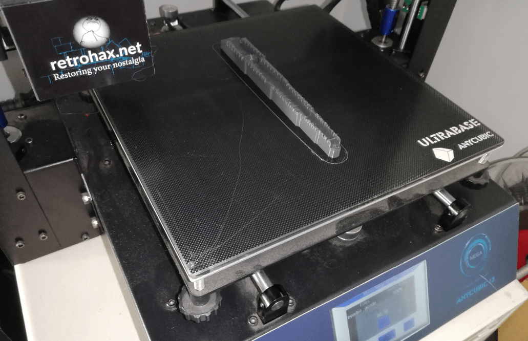
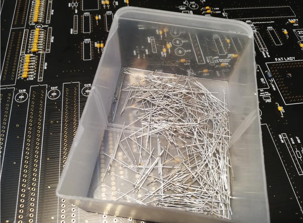
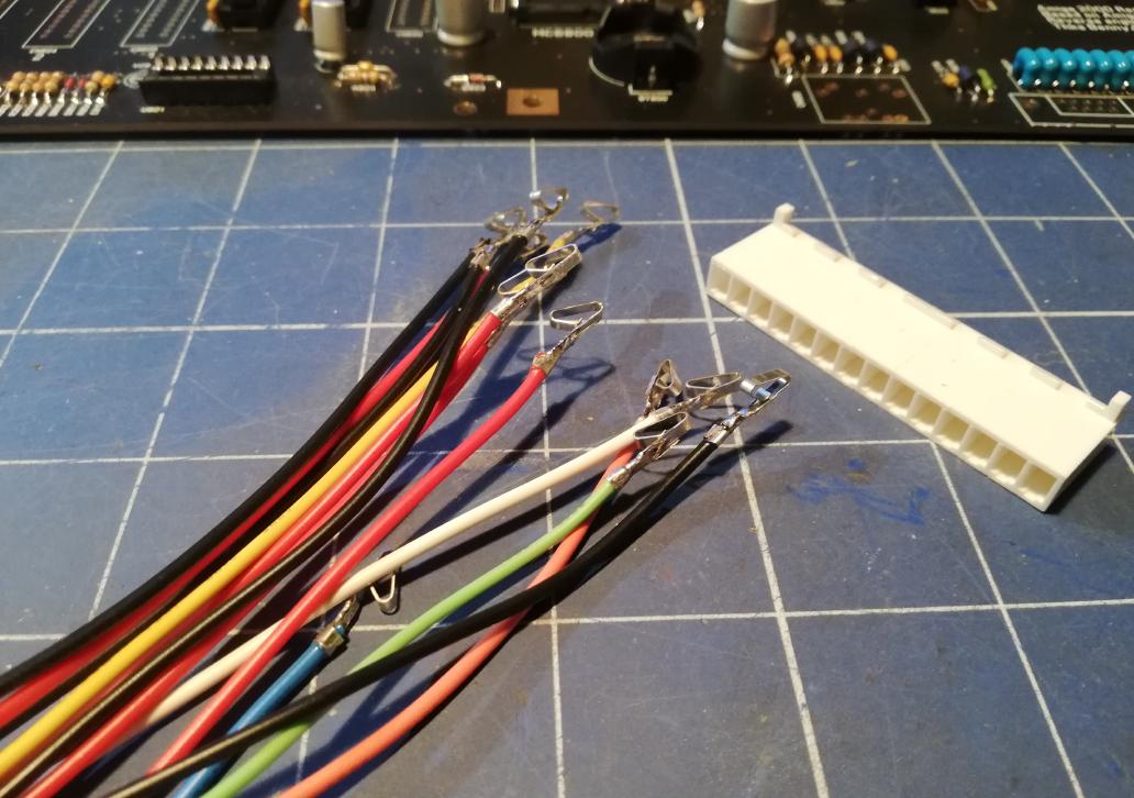
There are a lot of parts that need proper bending so I’ve figured that I’ll 3D print a tool for it.
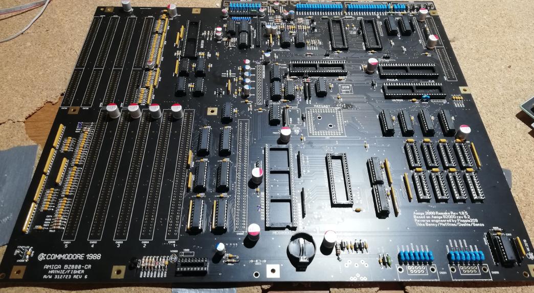
Soldering
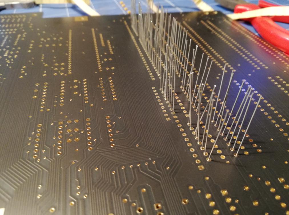
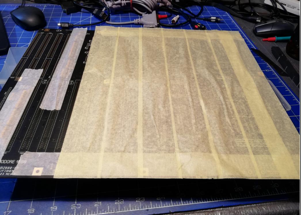
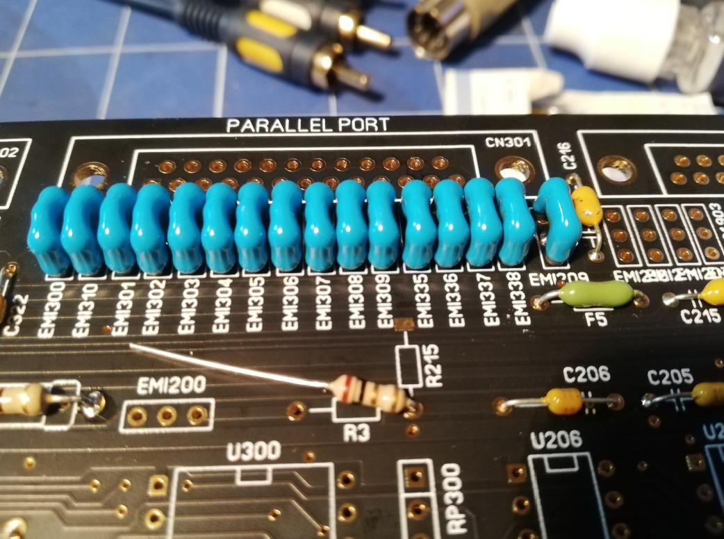
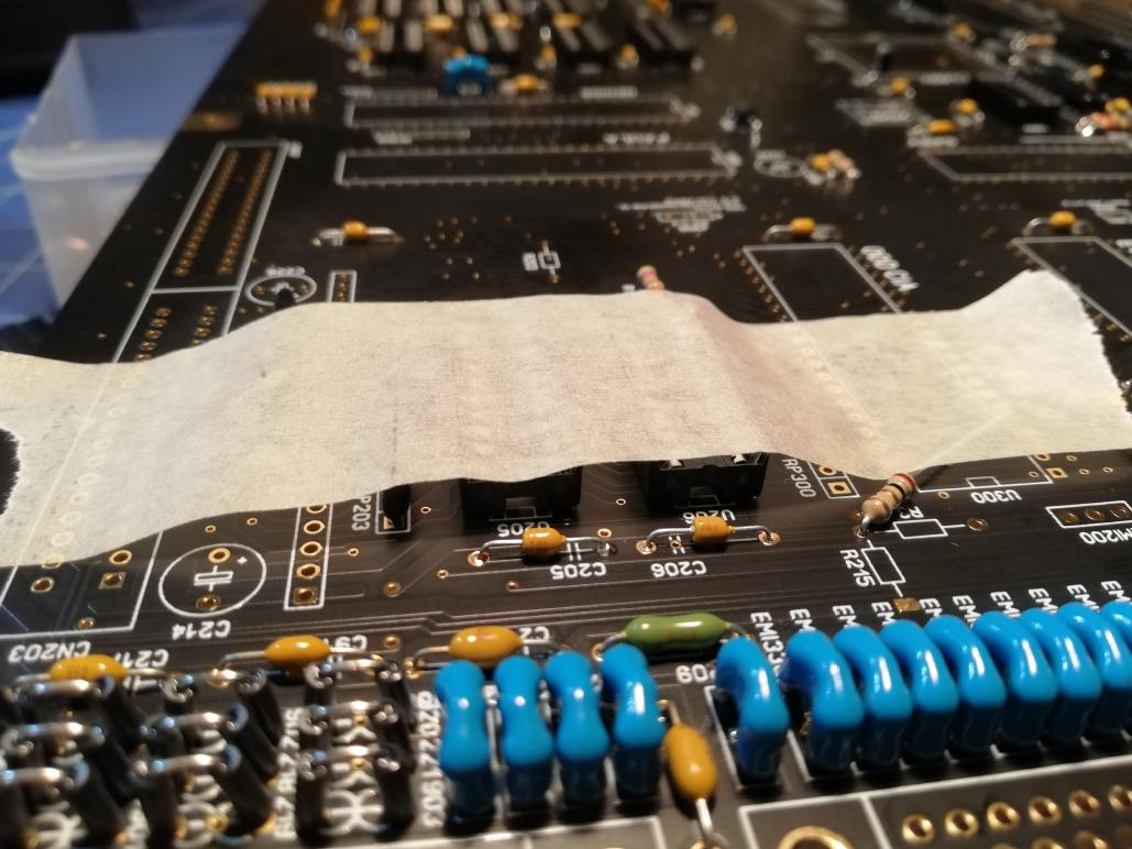
From now on, that was just a matter of bending parts and putting ’em in the place.
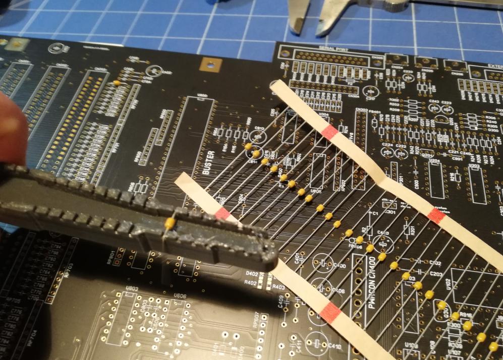
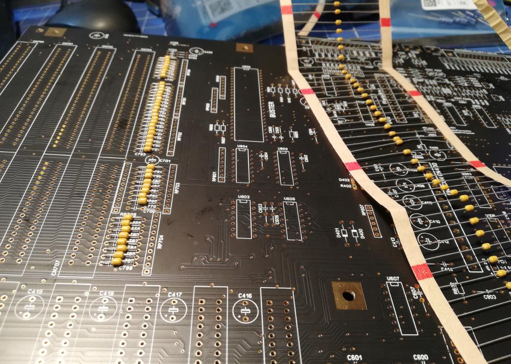
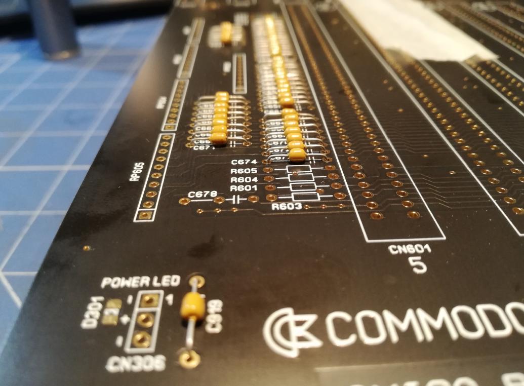
I’ve figured out that using paper paint tape to hold components in place makes the job way easier.
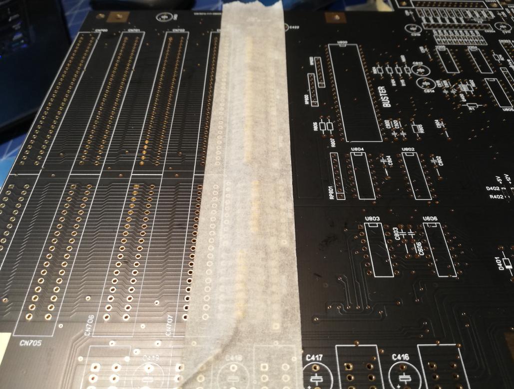
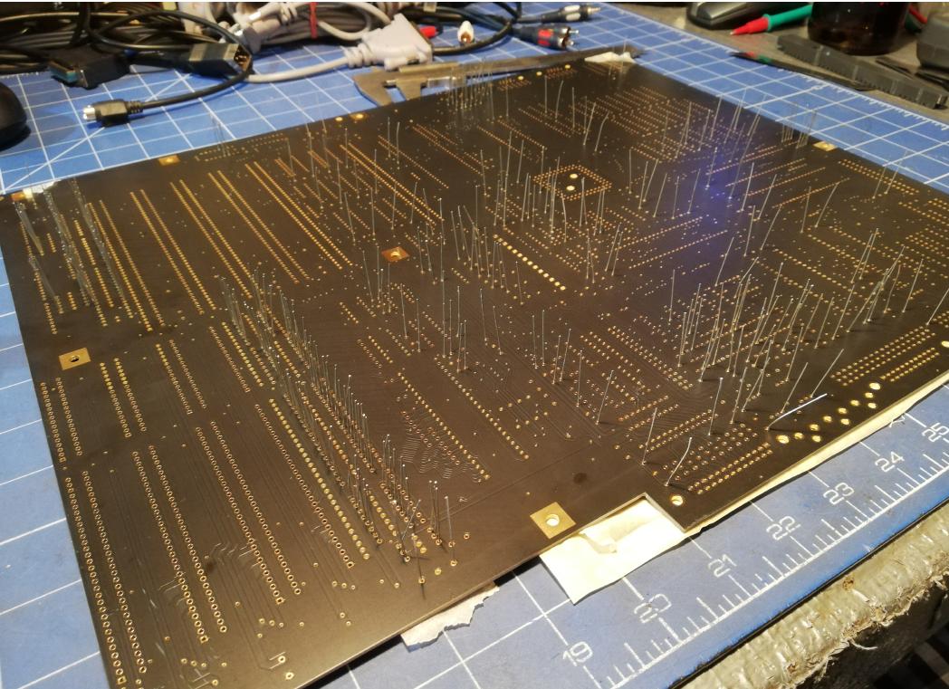
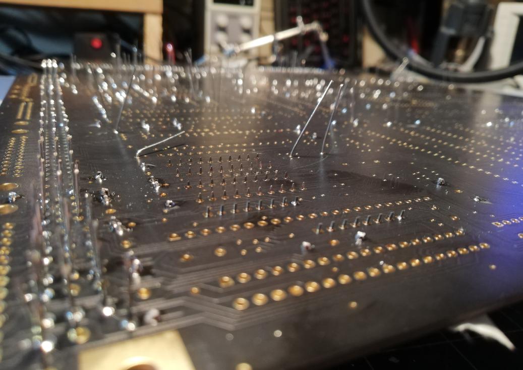
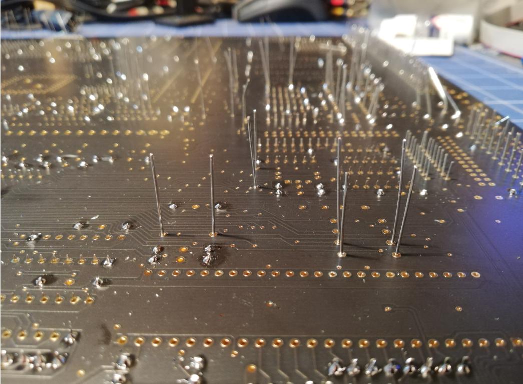
This is how it looks on the other side.
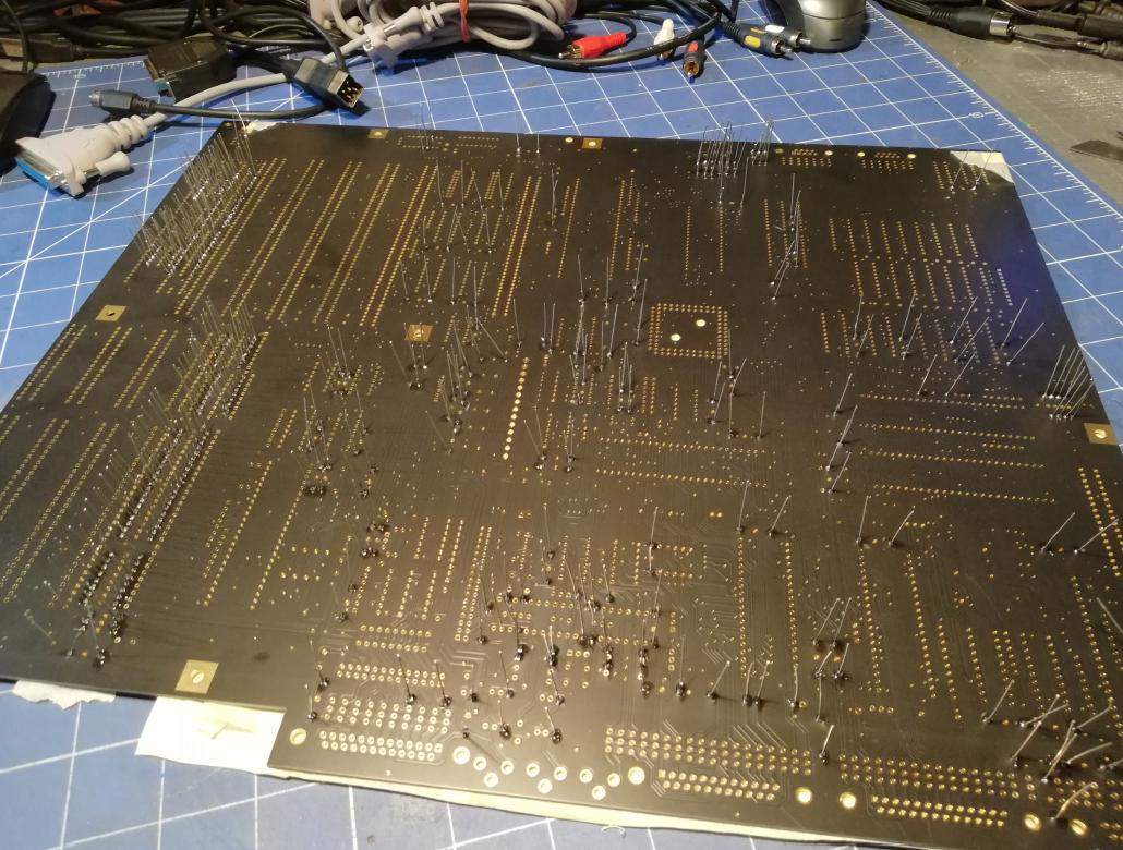
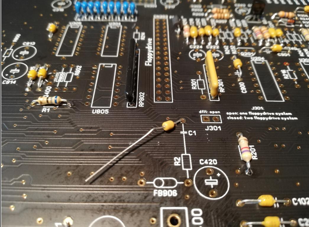
Some fails along soldering were introduced too 😀 Sorted out later, so no worries 😉
Always remember!! – DO READ readme.txt and documentation 😀
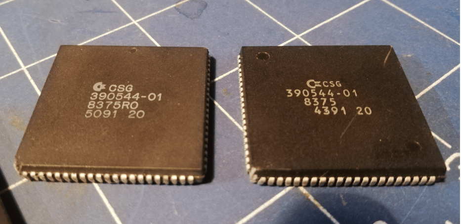
Now, to a great FAT AGNUS problem (you’ll see why this is important soon and in future posts too)
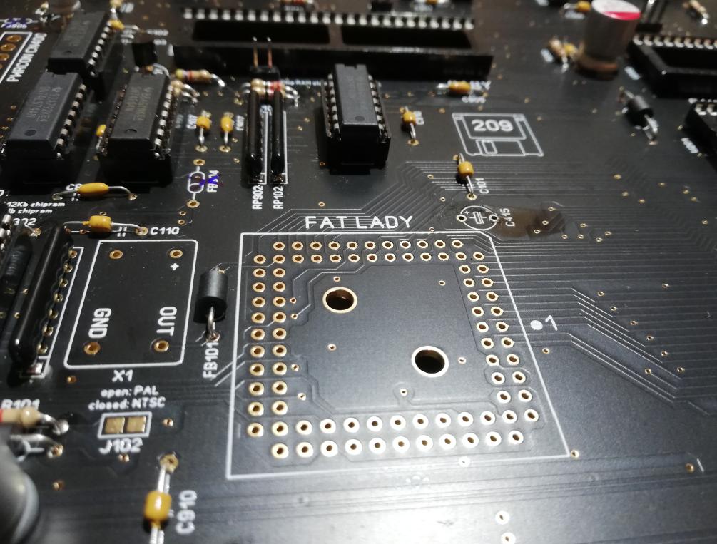
For now, just a teaser … Cheers rj1307!! 🙂
Some spare parts from a dead, donor A500 mobo + new sockets and ports
The PSU
Ok, so with the majority of passives in place, I could start working on the PSU. The first idea was to use a cool ATX to AMIGA adapter that I’ve already used in the A1K Phoenix project. I just had to rewire everything to match the A2000s power socket.
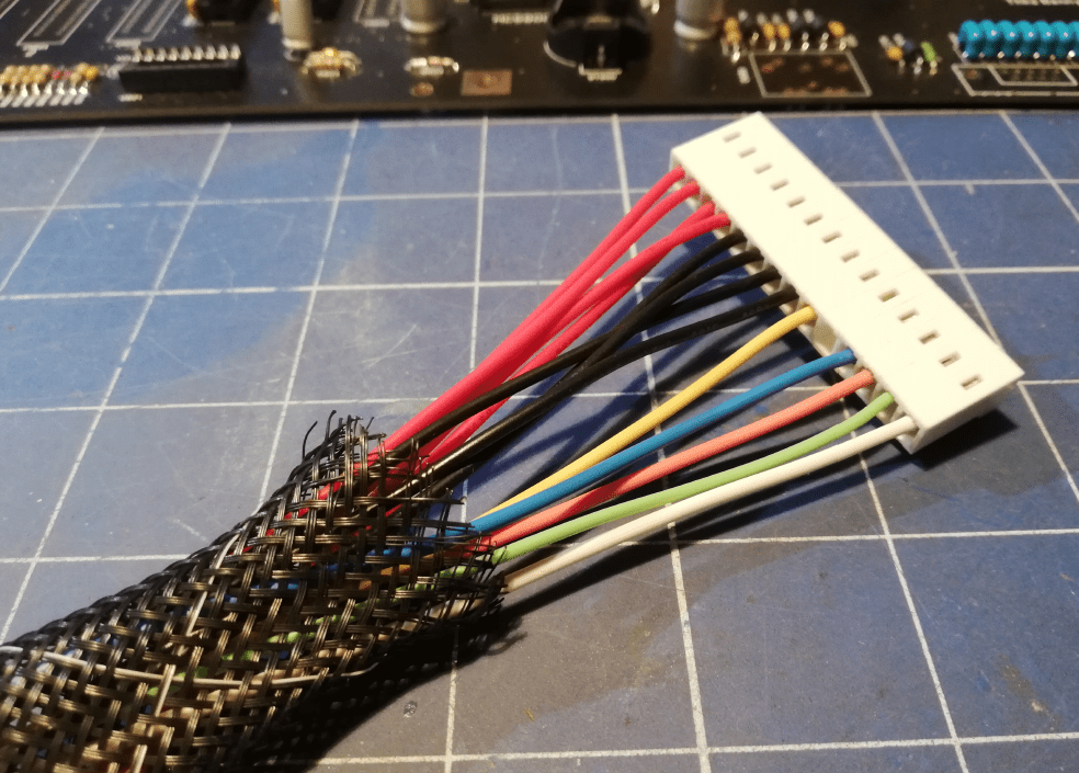
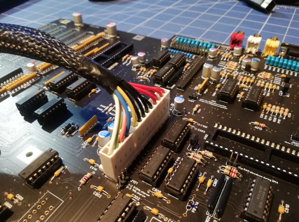
For those who are having trouble with figuring out the above wiring, here is how it goes:
From the top:
- RED – +5V
- BLACK – GND
- YELLOW – +12V
- SPACE
- BLUE – -12V
- ORANGE – +5V user
- GREEN – -5V
- WHITE – TICK signal
Testing time! … without custom chips!

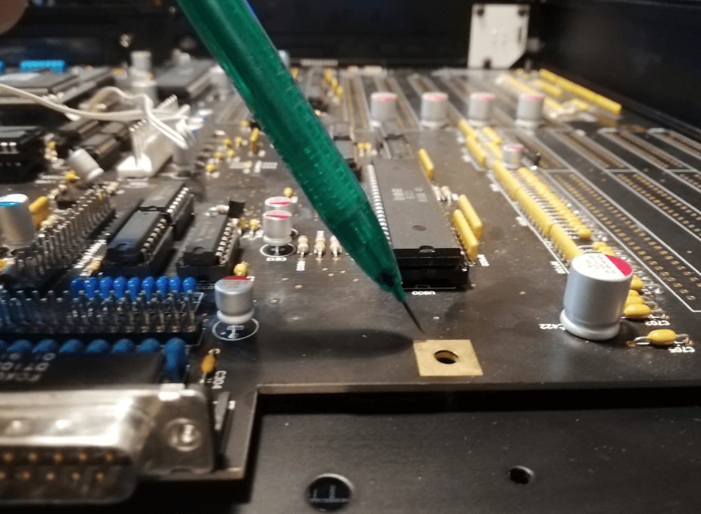
Custom chips
Now, with passives in place and successfully tested without a magic smoke, I could move on to testing the setup with custom chips.
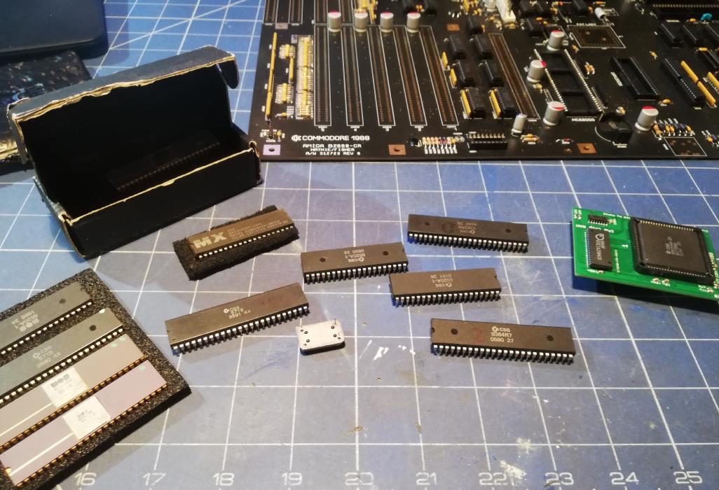
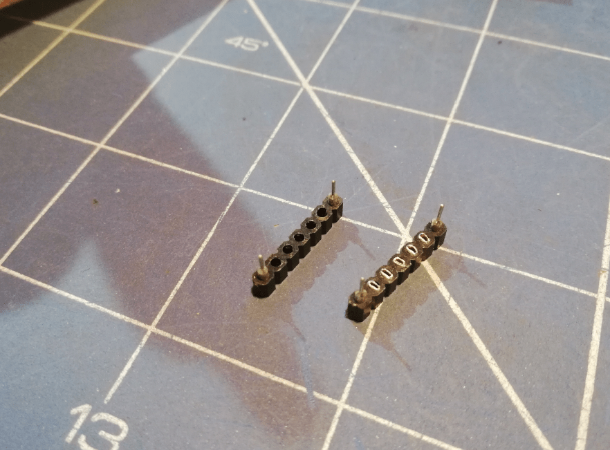
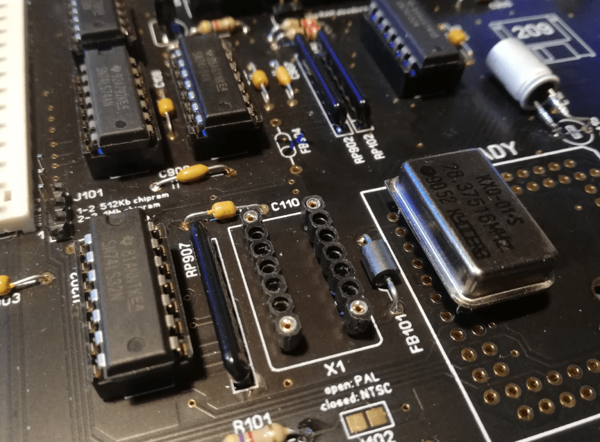
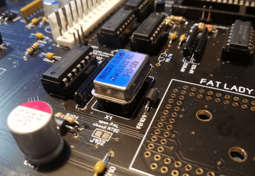
I wanted to make a quartz resonator replaceable so I’ve come up with an idea to cut a precision DIP socket proper size and remove unnecessary pins. This allows you to easily replace the part without serious soldering hassle. On the left, pins were removed.
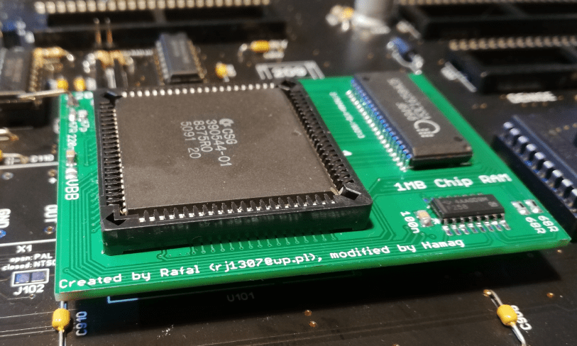
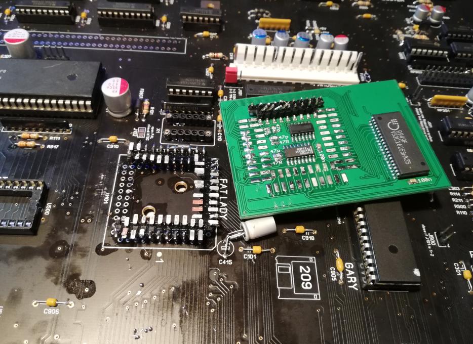
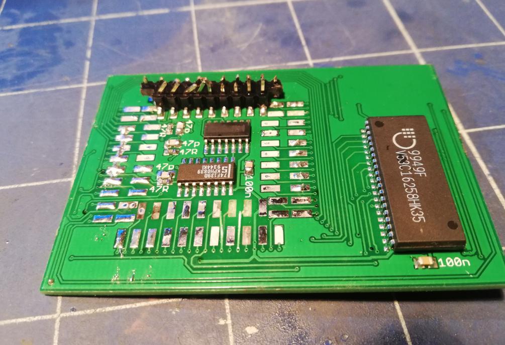
The next piece needed to run the whole unit was to install a FAT AGNUS chip. MrTrinsic wanted this Amiga to have 2MB of CHIP RAM. This was supposed to be done by a mod installation. There were some problems (as usual:) introduced. The first problem was a capacitor collision but that was easily sorted out by resoldering it.
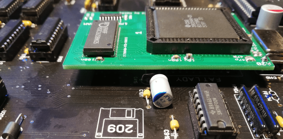
The second problem was that this mod didn’t work with this mobo … sadly, I’ve figured that out after soldering it on …
I had to desolder it, and that’s when problems started. Turns out (no shit Sherlock) that it is kinda hard to desolder standard gold pins from a brand new, gold-plated motherboard.
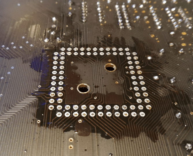
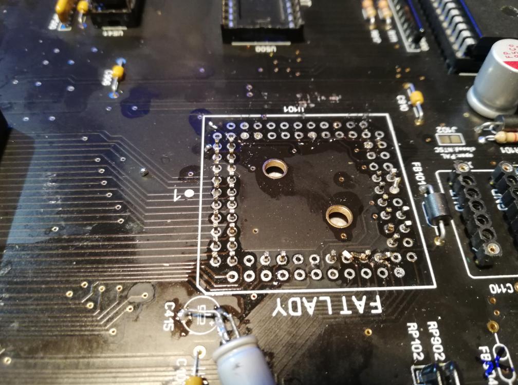
No worries, the module was brutally removed but was rescued afterward and will be used in another project 🙂
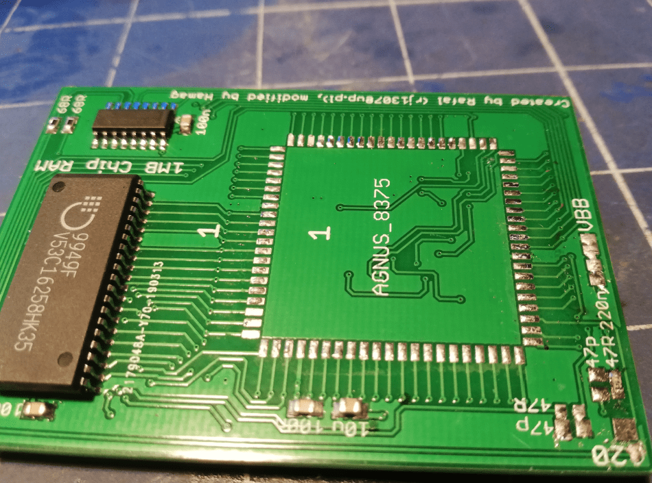
Anyway, I had to install a standard PLCC socket and put a regular FAT AGNUS in it just to test if it all works.
Aaaaaaand…
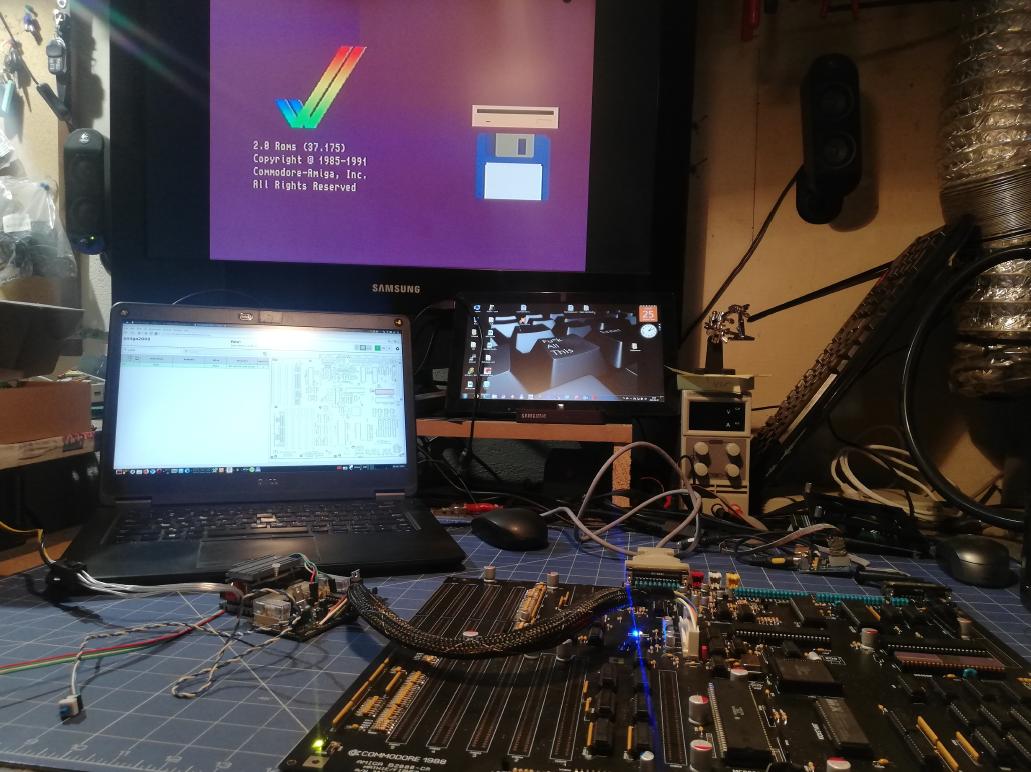
It worked!!! YAY!
The Case
Now, with a working mobo as a base, I could move on to early measurements of a case.
MrTrinsic figured out that we should be OK with “such a large” case for A2000
However, there were a lot of things that had to be sorted out first to make it all happen.
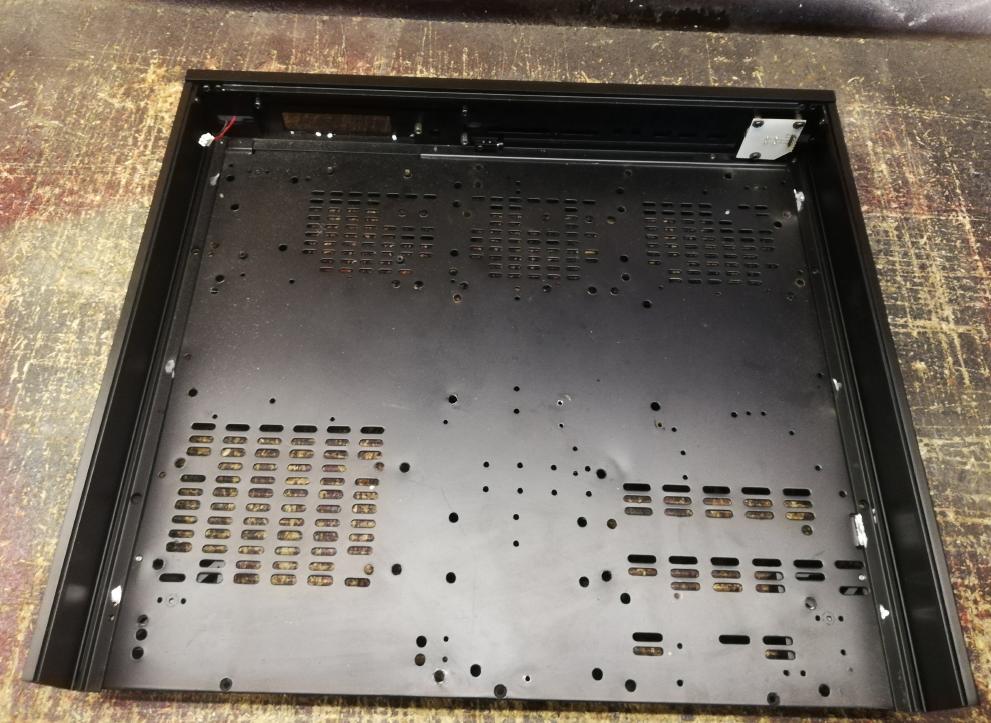
The case that MrTrinsic picked is TF5 type. It was sold by Karma Digital, Omaura, and Aumro.
Here is how it looks.
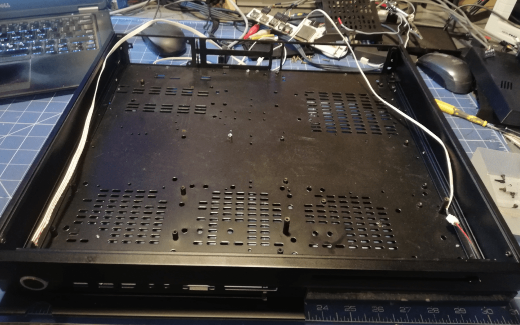
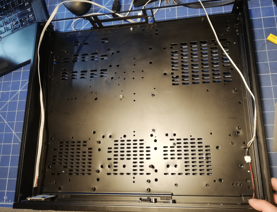
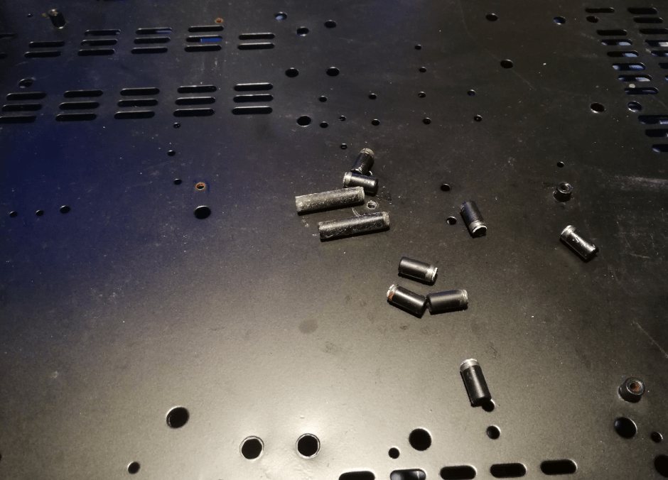
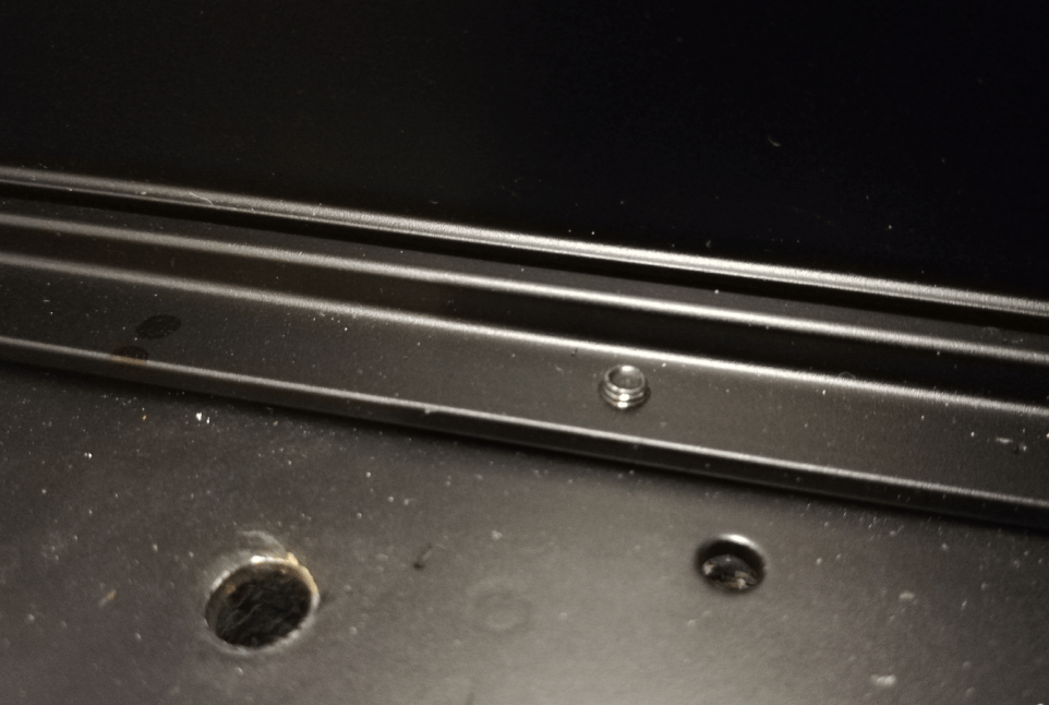
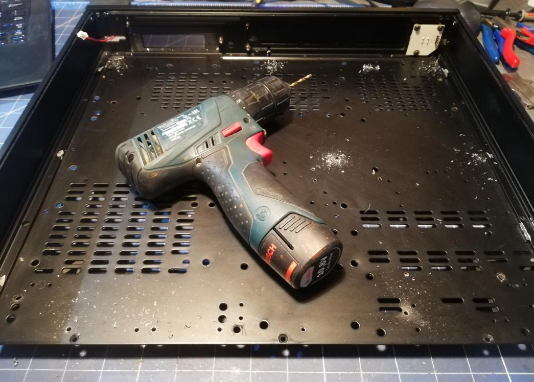
I didn’t waste time and I started working on it. One of the first things that had to be done was to remove all those studs designed for PC motherboards.
The first measurements followed quickly.
It quickly turned out that I can work on some improvements by simply cutting off the tips of screws to save 2mm of space.
That task was sorted out by the Dremmel-like tool. I’ve also removed other minor obstacles along with screw tips.
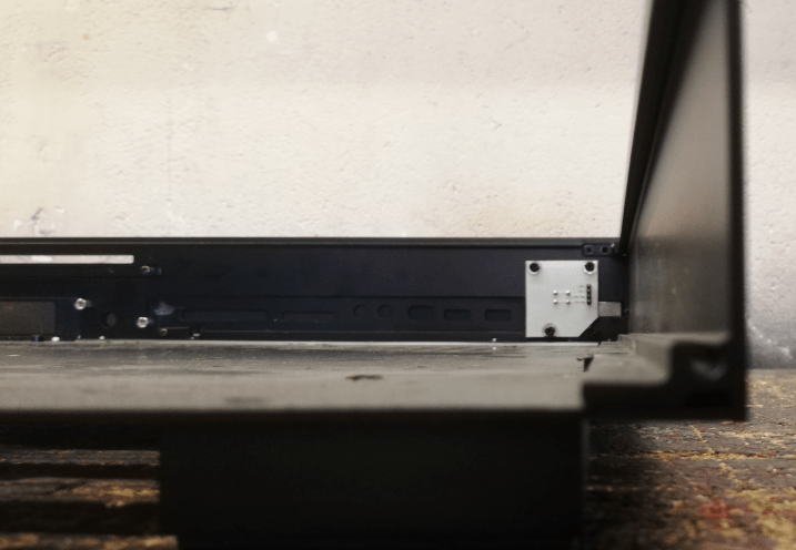
With everything flatted out, I could start working on new mount points for a freshly made A2000 mobo.
After a while …
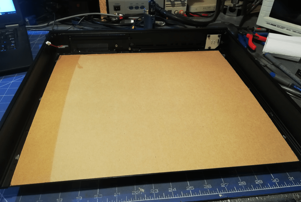
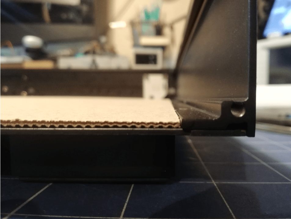
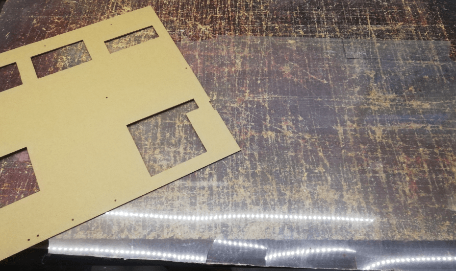
Isolation
I first made a template out of cardboard and used it to carve a proper polyethylene sheet to place it underneath a mobo as a separator.
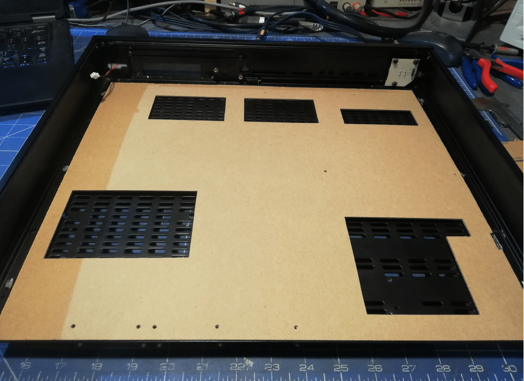
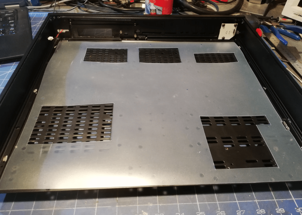
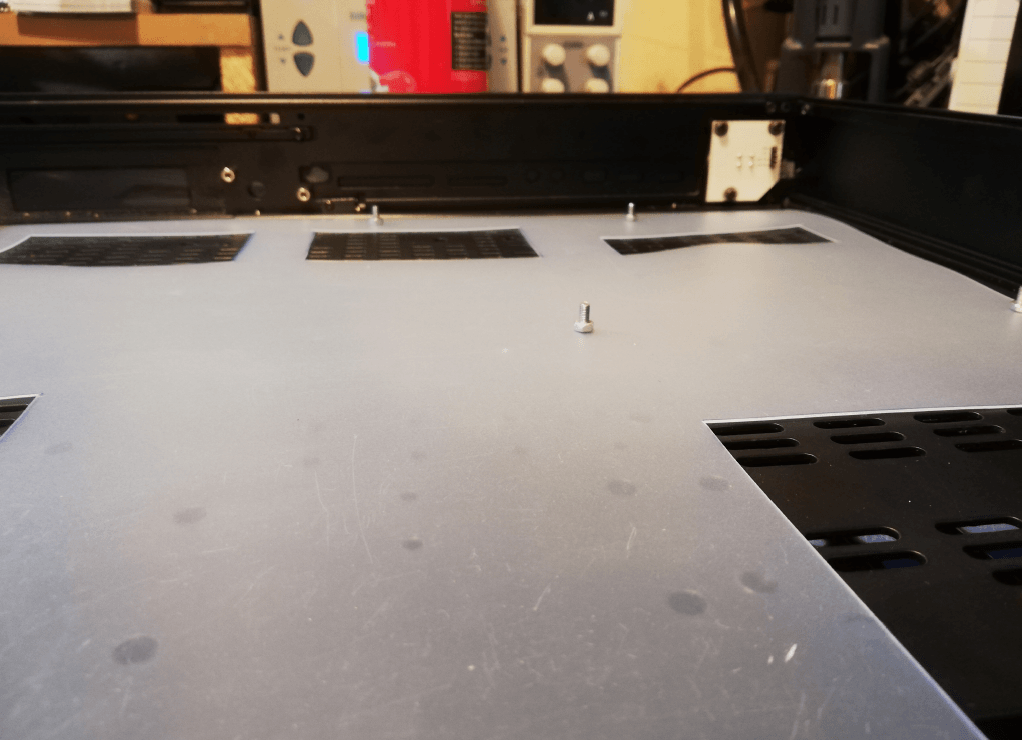
W00t! motherboard fixed in place!
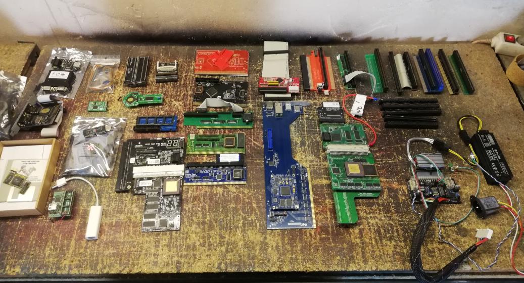
Now, let’s put some goodies into it 😀
The first part of add-ons and mods showed up. Not all add-ons will go inside but let’s leave it for future posts.
At the end of part one
This is it for now. Stay tuned for at least four more posts. Below is a short teaser 😉
Outro
If you want to get the retro gear I am manufacturing or hardware modules, please visit shop -> https://retrohax.net/shop/
Please support my work by commenting here and on our Facebook or Twitter pages.
If you want to donate a dead computer then drop me an email. Extreme cases are welcome. – Nobody donates anything. so don’t bother. Looks like only Youtubers get all goodies LOLOL ;P
Awesome work, fantastic to read and really big congratulations to your patience
Thank you!
Great work. Which Agnus-2MB-chipmem-Mod did you installed which works with the mobo?
Thank you 🙂
The mod is ACE from iComp
Thanks for giving me the feel I am doing a part in here while you are actually working wonders. Like “I just had to rewire….” man I would blow up the planet if I tried stuff like this :D.
The TF5 case was actually picted for a specific reason.
For a very short time, there was a company “Commodore USA” who did bring small PCs in cases such as a Commodore C64.
In the long run on of their ideas was to do a linux distribution looking and feeling like Workbench.
The case for this new “Amiga” was the one you are looking at here.
Unfortunately, the man behind that Commodore USA died and after this the driving force was gone.