…or are you done yet?
<intro>

Links to the previous four posts are below:
Ok, without further ado (courtesy of Adrian’s Digital Basement – cheers buddy:) let’s continue with this hardware pr0n 😀
</intro>
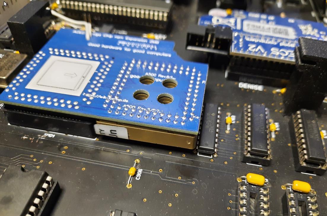
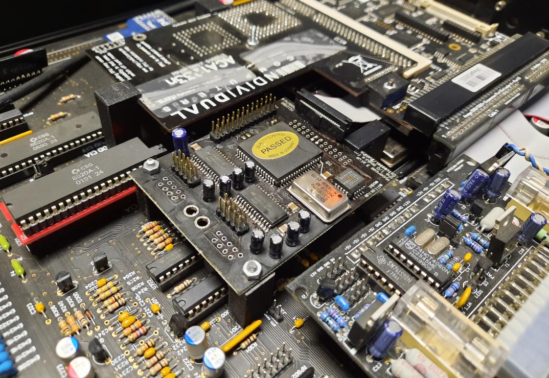
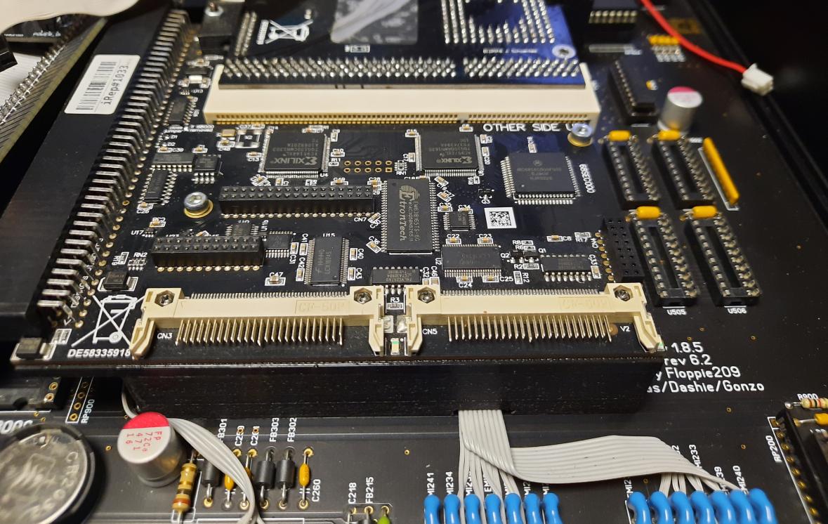
The ACE Chip RAM mod issues
I’ve already mentioned it in one of the previous posts but let me repeat it.
This mod was an actual headache as I was getting random issues because of it.
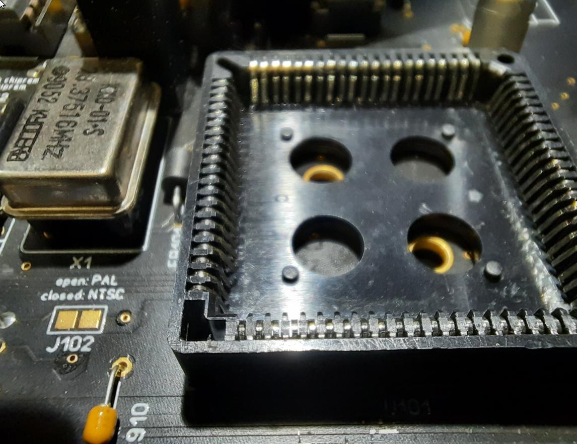
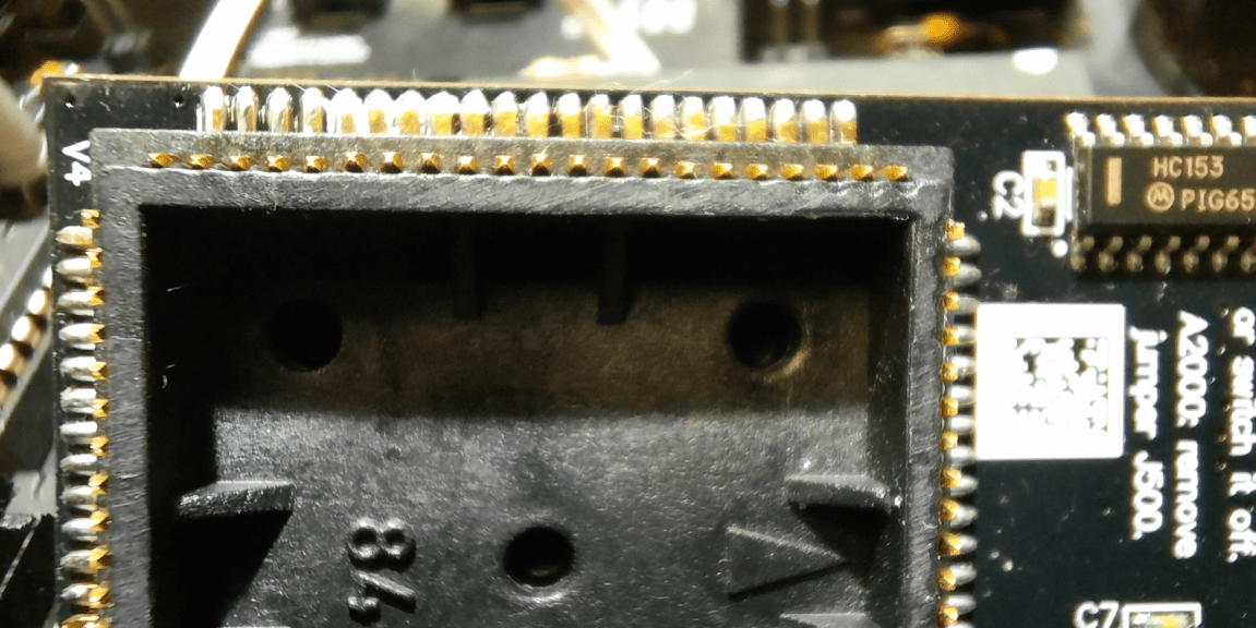
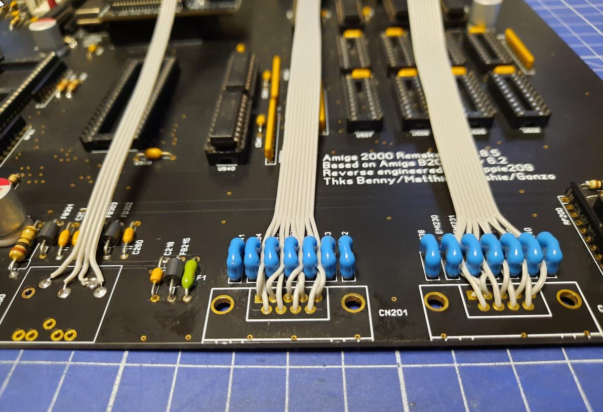
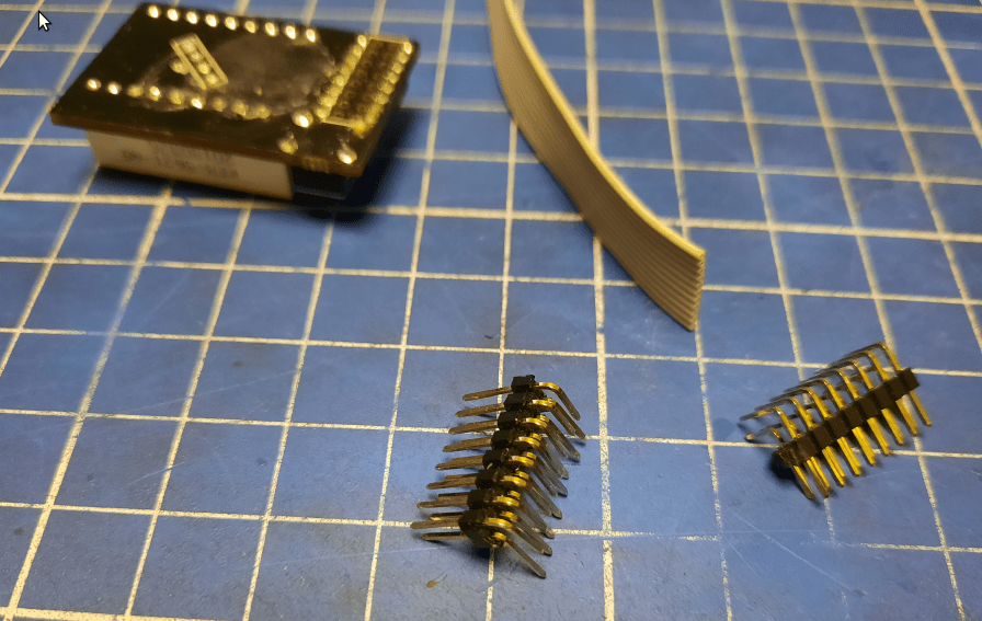
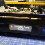
Here is a pic that shows it all.
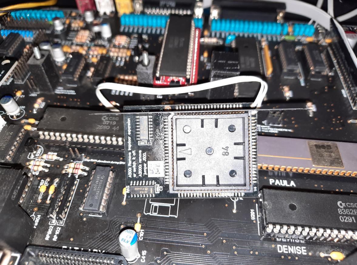
As you’ve probably noticed, PLCC is not even. This resulted in a bad connection and random GURUs or hang-ups.
I’ve tried prying pins on a socket and a plug itself but after a few hours, the problem returned.
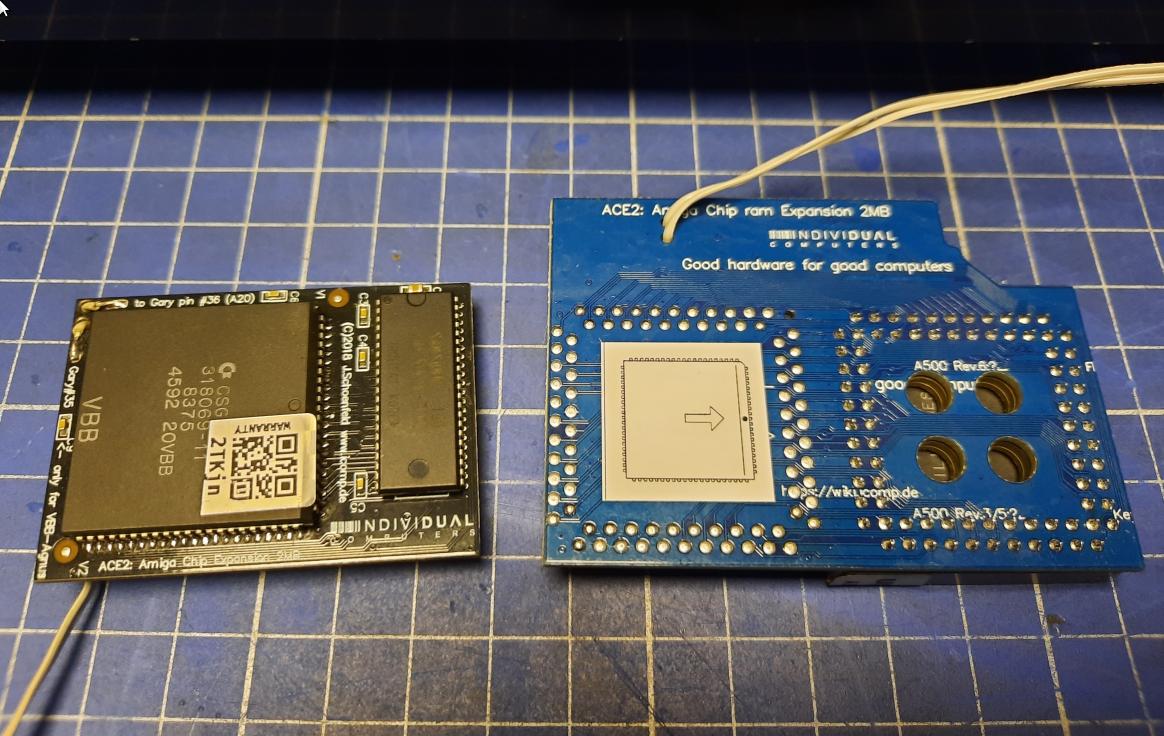
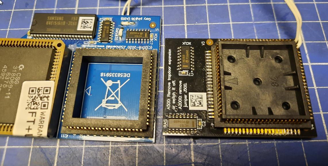
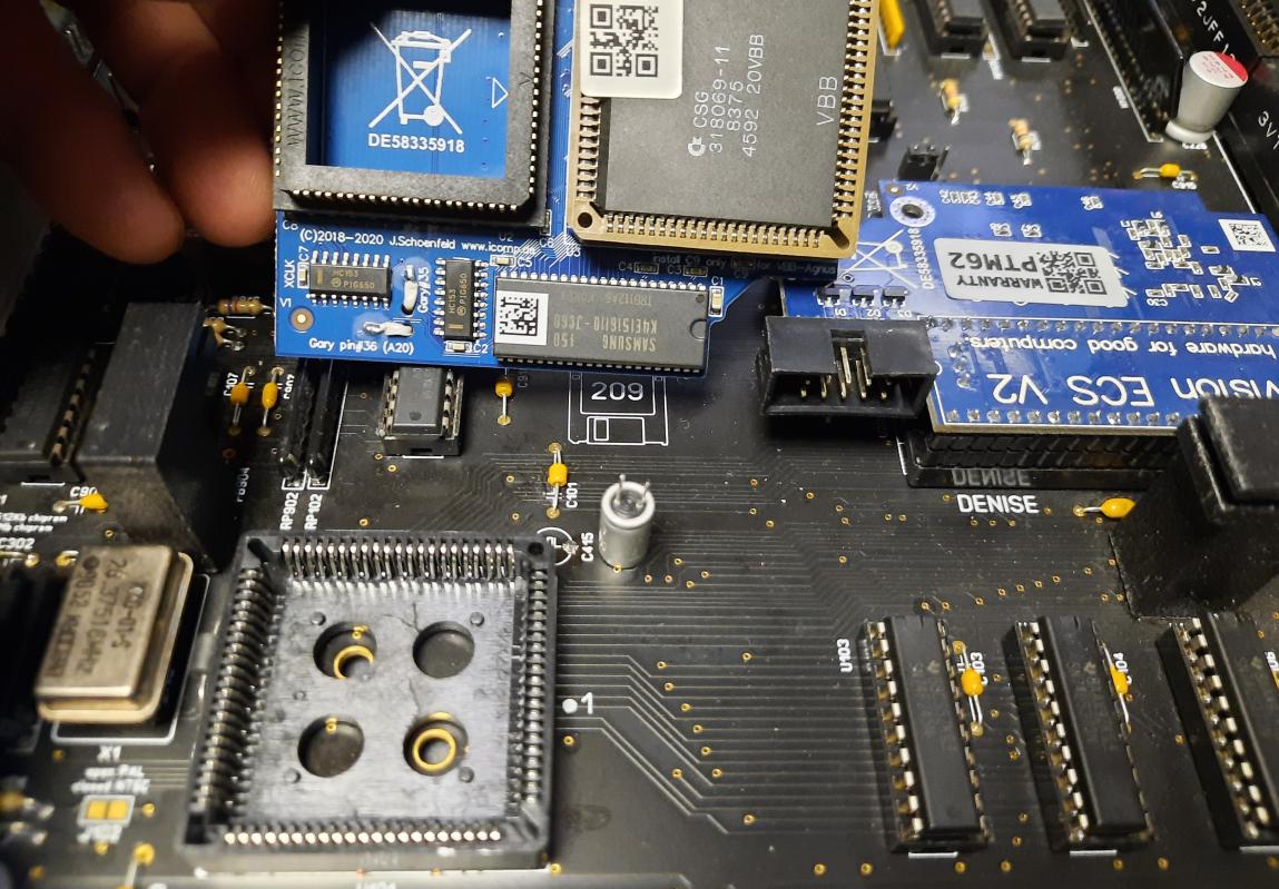
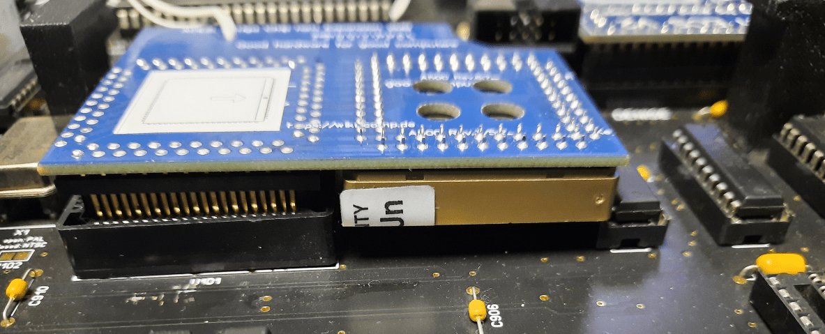
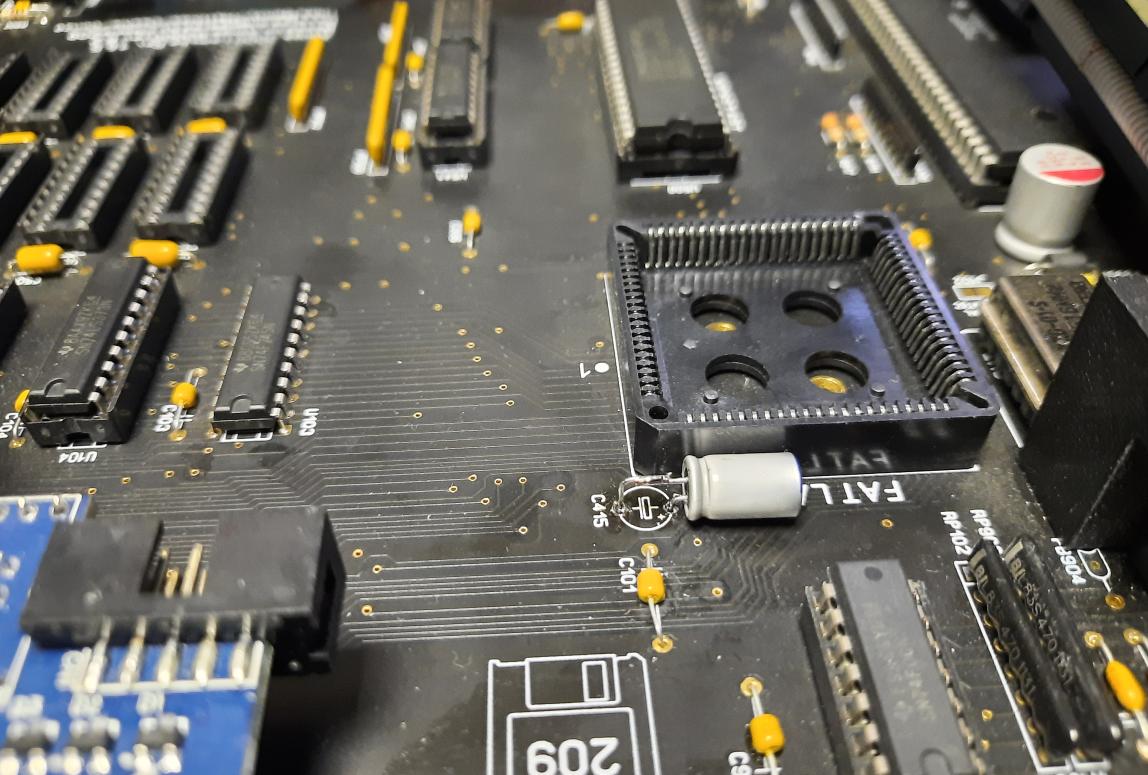
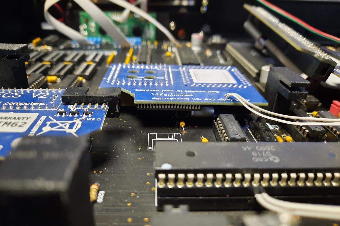
After replacing the old version with the new one, most of the issues were resolved. Don’t worry though, there are tons of other issues that are still to be sorted 😀
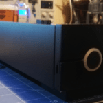
DVD drive on top of ACA500+
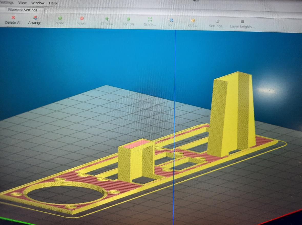
Next on the list was a DVD drive that needs to be placed on top of ACA500+, but that requires some 3D printing that will separate these parts and serve as a base for the DVD drive.
It took me a while to design this particular part …. and even more to properly 3D print it(and re-print it later lol).
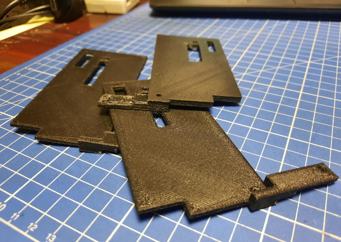
Finally, I came up with the final design but I had to reprint it later one more time because I didn’t like some details 😉
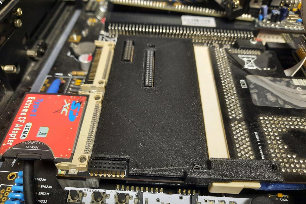
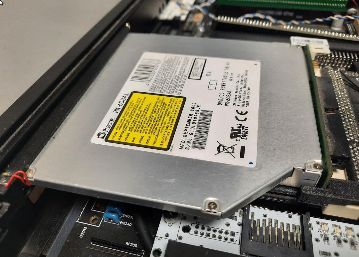
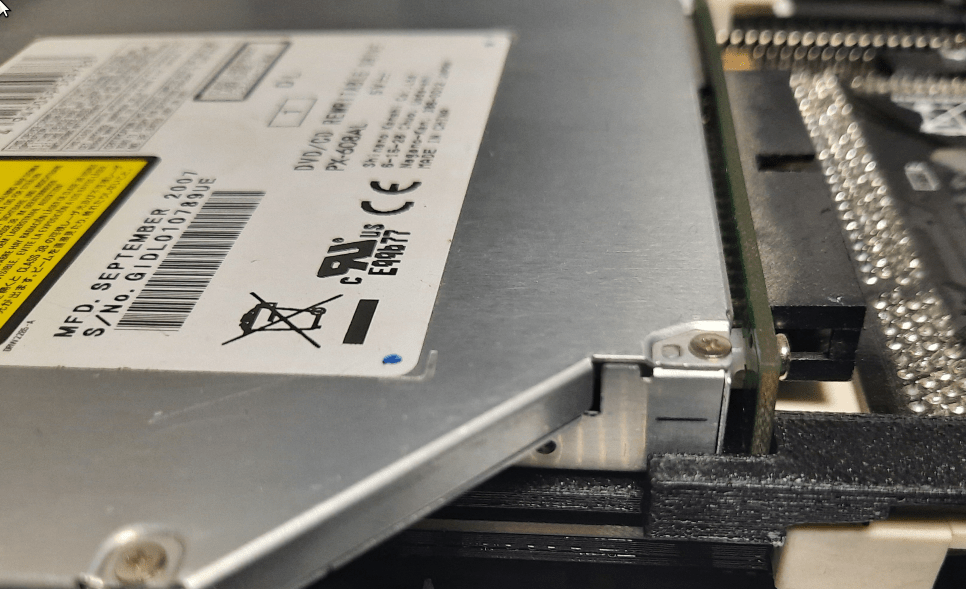
The DVD drive is attached to the case via two screws on both sides of the bracket that I’ve described in previous posts.
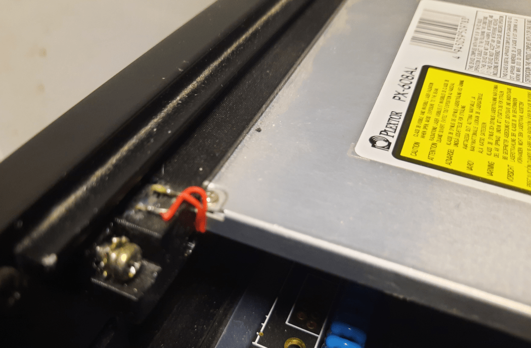
I’ve also figured out that the perfect spot for RapidRoad USB will be right next to the DVD drive.
I just had to design another plastic part for it(it will be covered later)
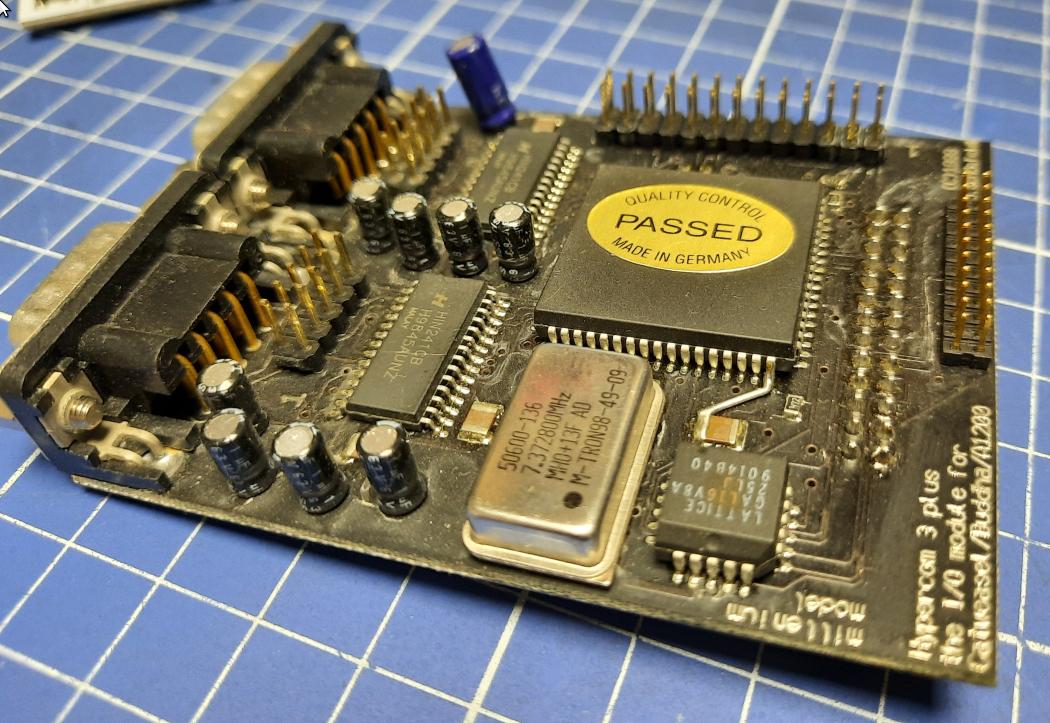
Hypercom3+ mount
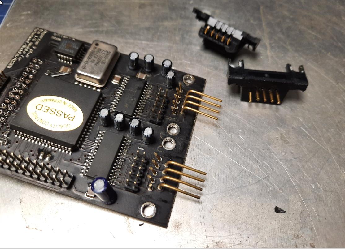
After a lot of thinking, I’ve found a good spot for Hypercom3+ mod. The perfect spot was between a PSU and ACA1233n but I needed to create some 3D-printed studs for it, plus, I had to remove some original parts from its PCB.
Here is how it looked … and yeah, it is all covered in dust as this project is going on for a looooong time 😉
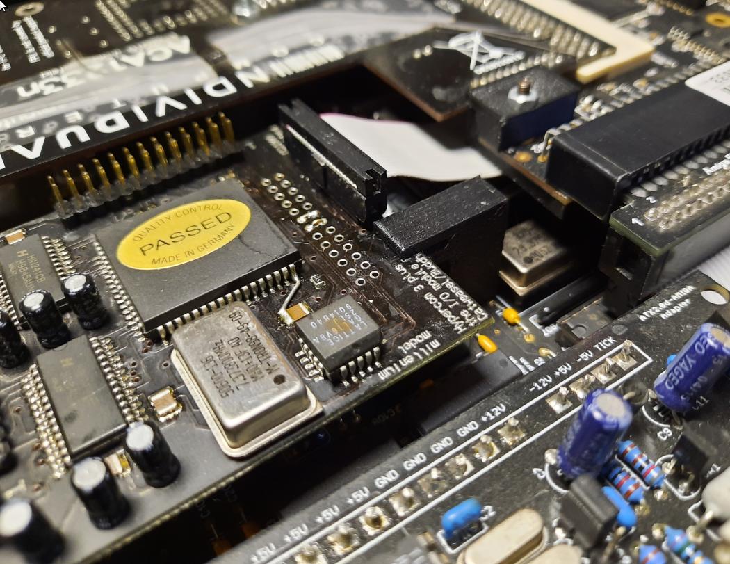
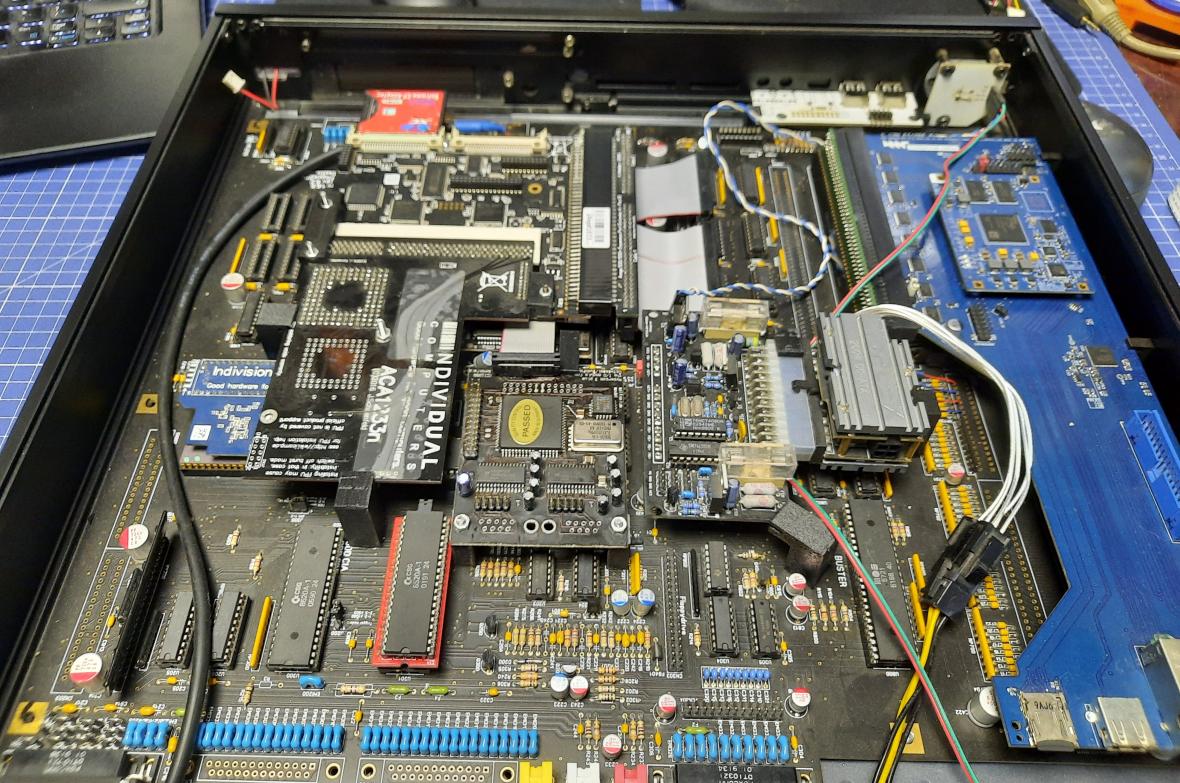
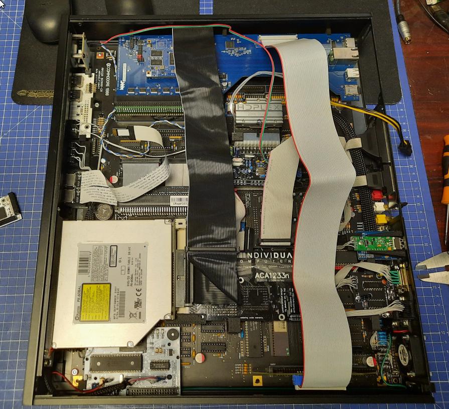
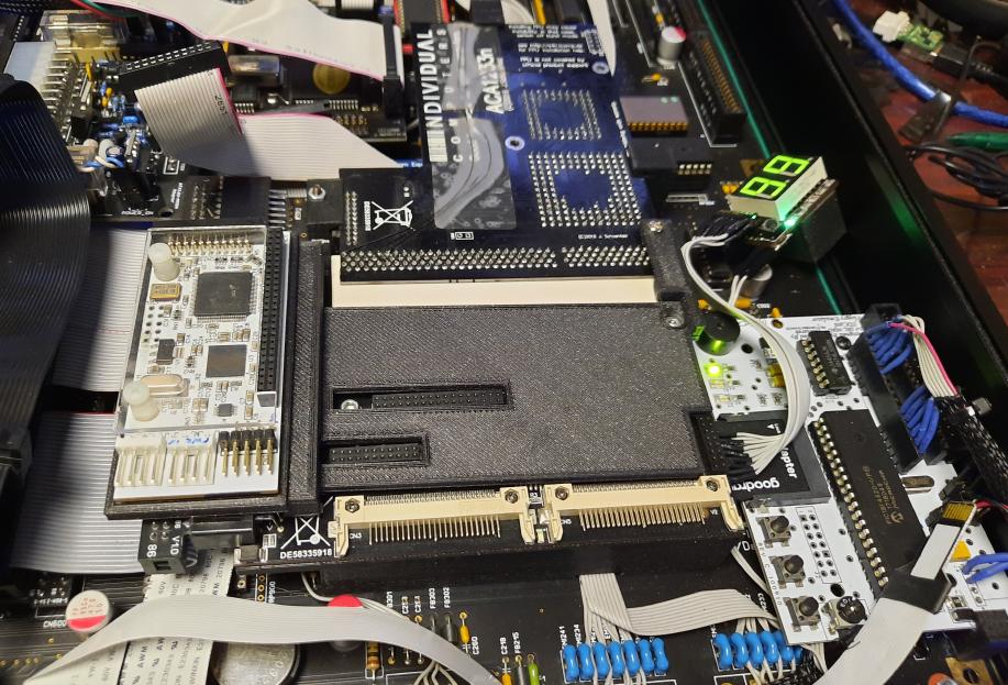
The top view at this stage. (without DVD drive)
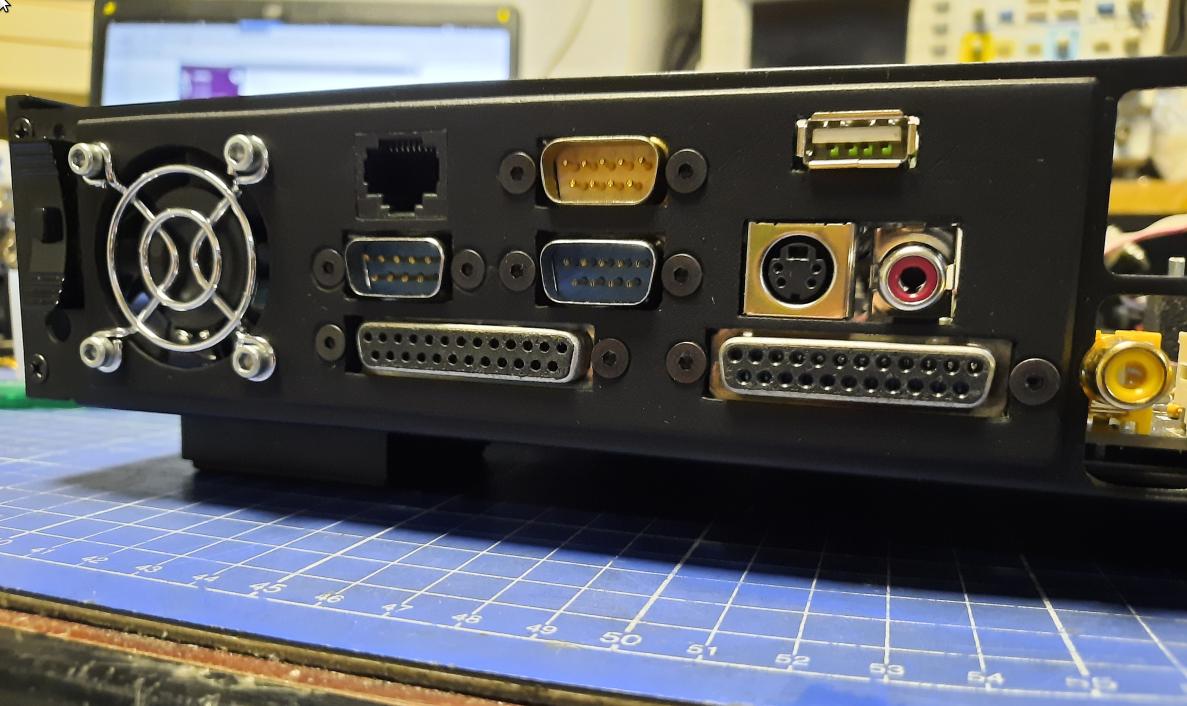
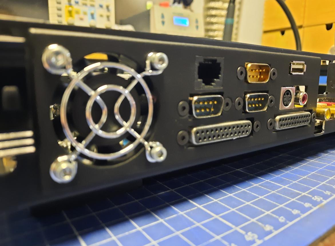
2/3 of a back panel
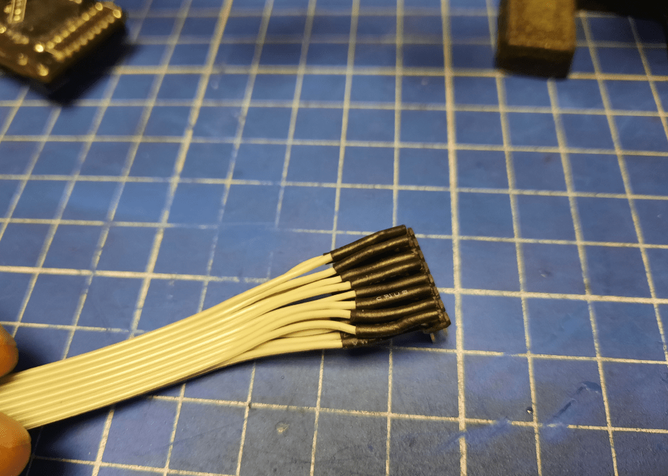
To start working on the back panel, I had to sort out the wiring that will be moved from the front of the PCB to the back panel. This includes Joy/Mouse ports and a keyboard port that is converted to a USB through an adapter described in previous posts.
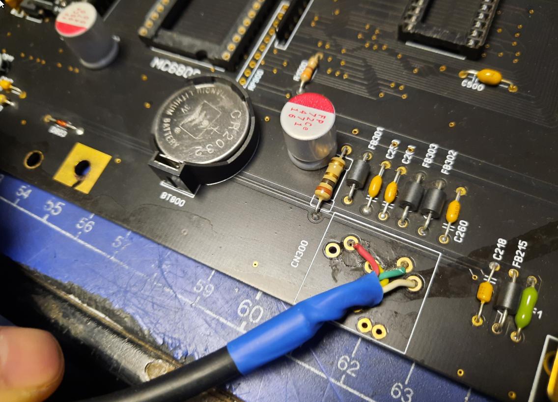
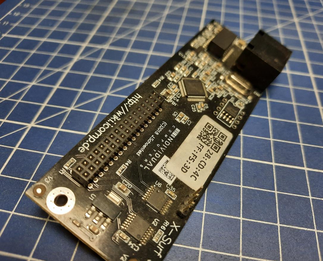
Another mod that needed modding (duh… excellent English skills sir…) was an X-Surf-500 attached to ACA500plus.
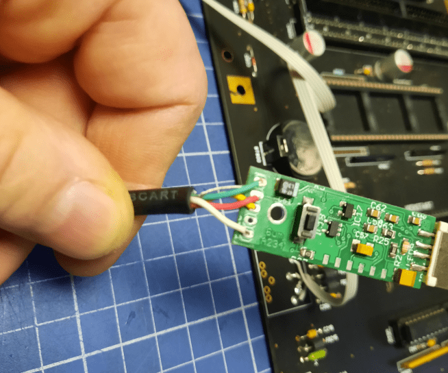
However, the ethernet RJ45 that is inside a case is quite useless so that had to be changed.
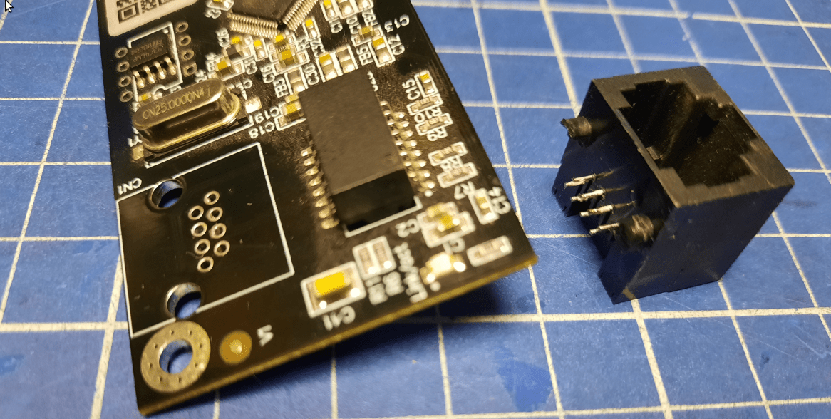
Wiring chaos is incoming! 😀
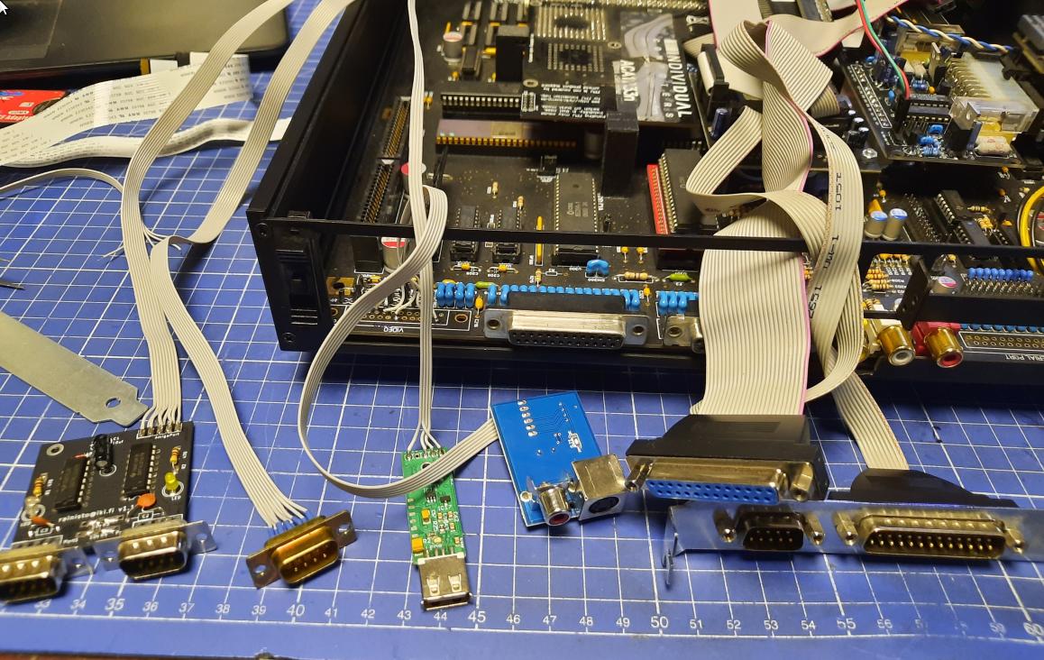
The first design started to emerge.
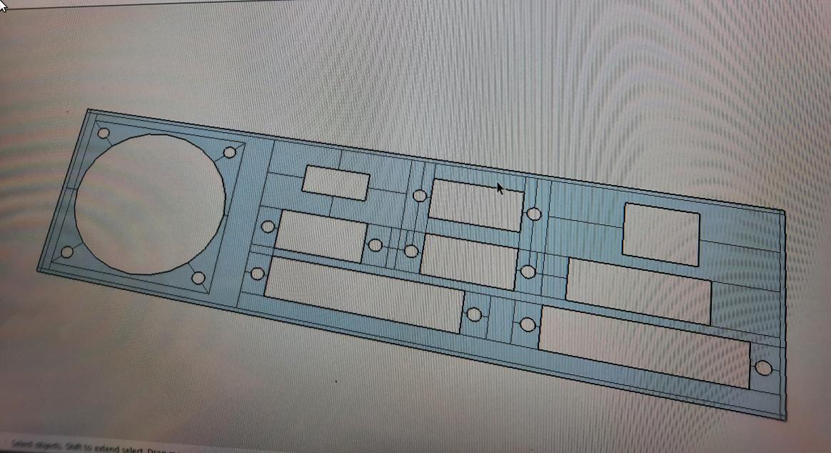
Shortly after the above, new ideas came to my head. Below is a short pictorial of how the process looked.
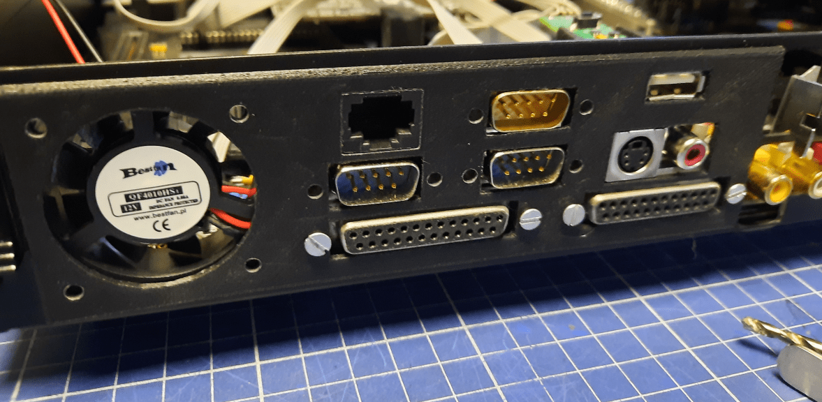
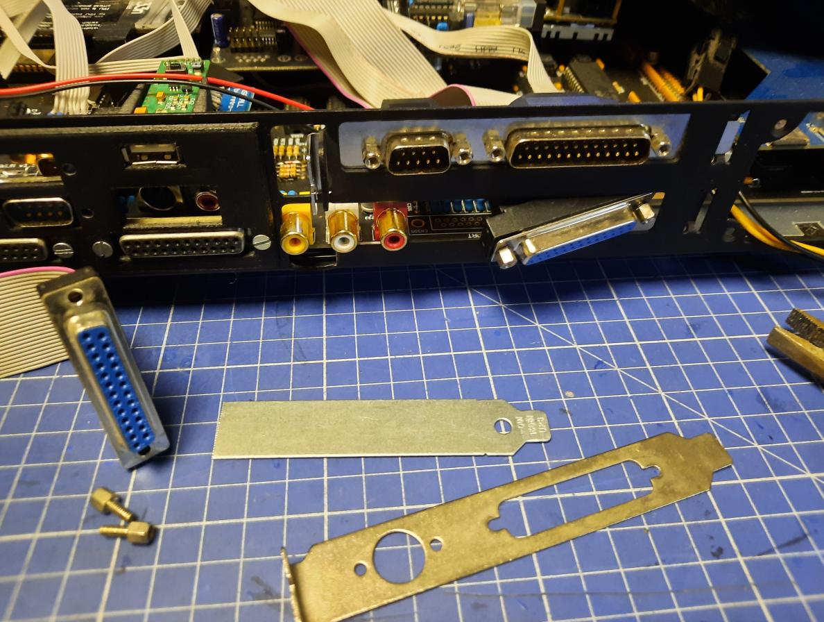
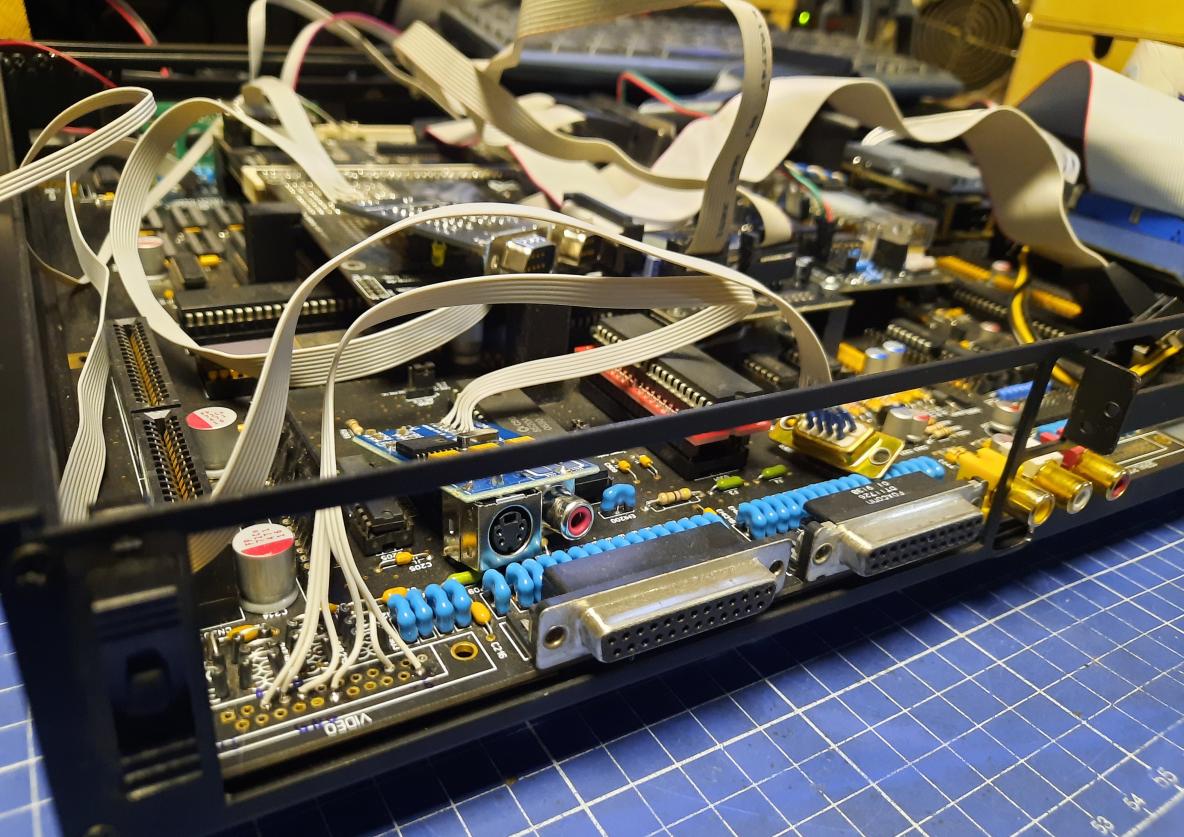
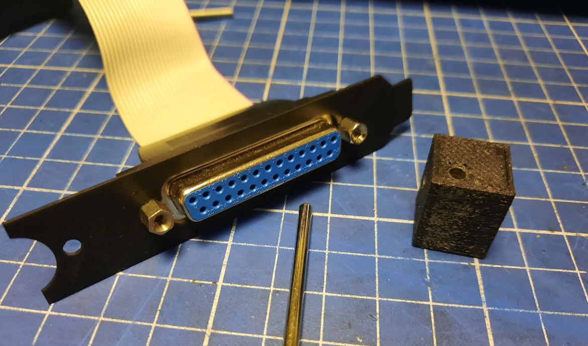
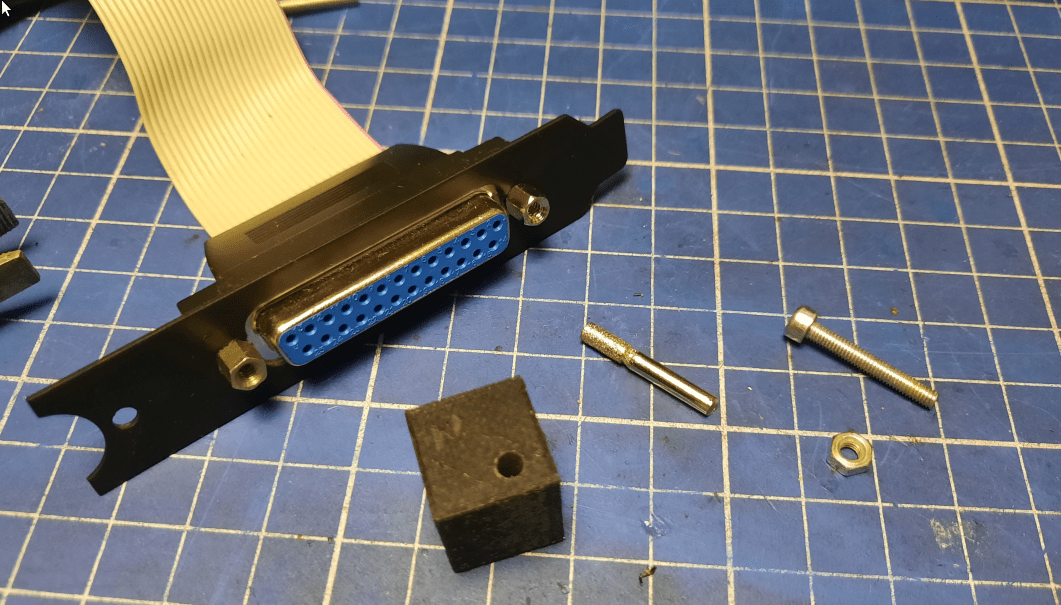
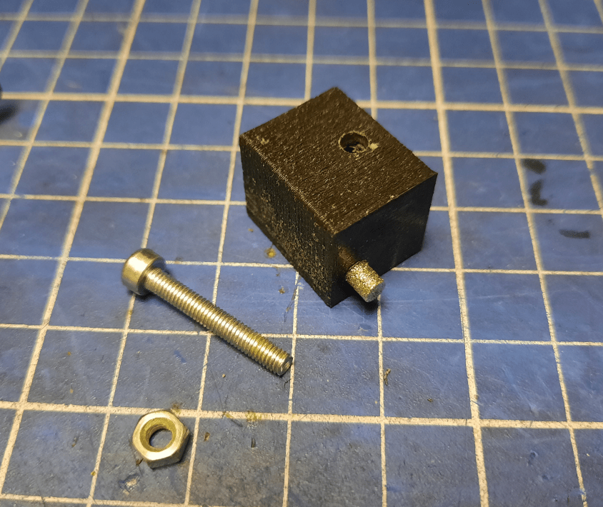
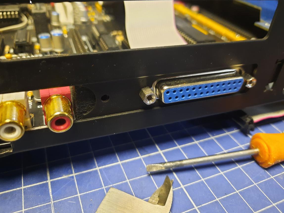
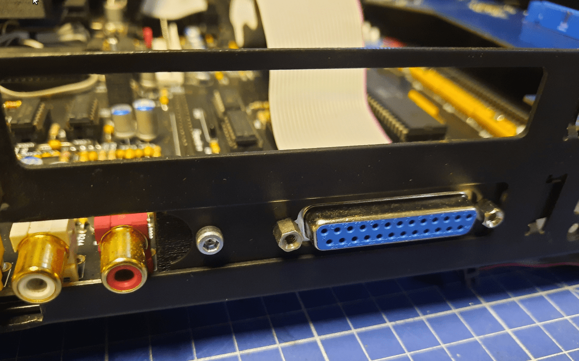
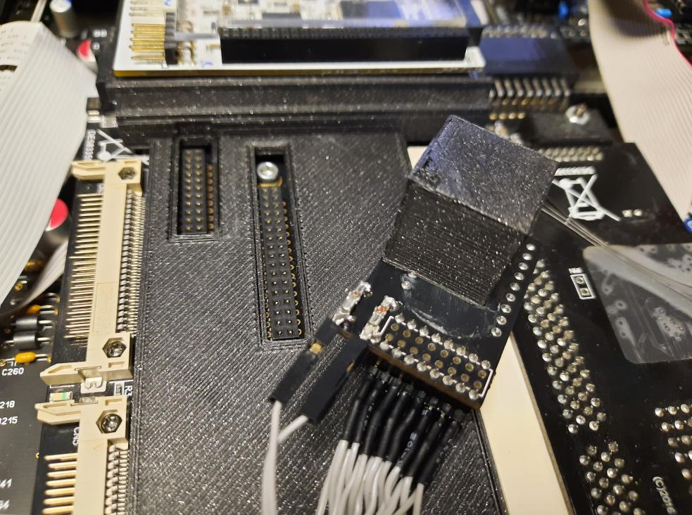
The original serial port is not connected (it might be changed in a future post … who knows:). Instead, the DB25 parallel port from Hypercom3+ will take its place.
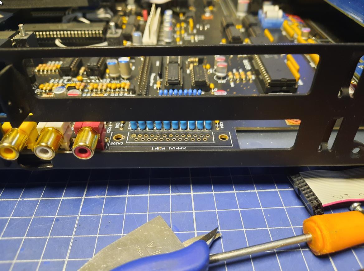
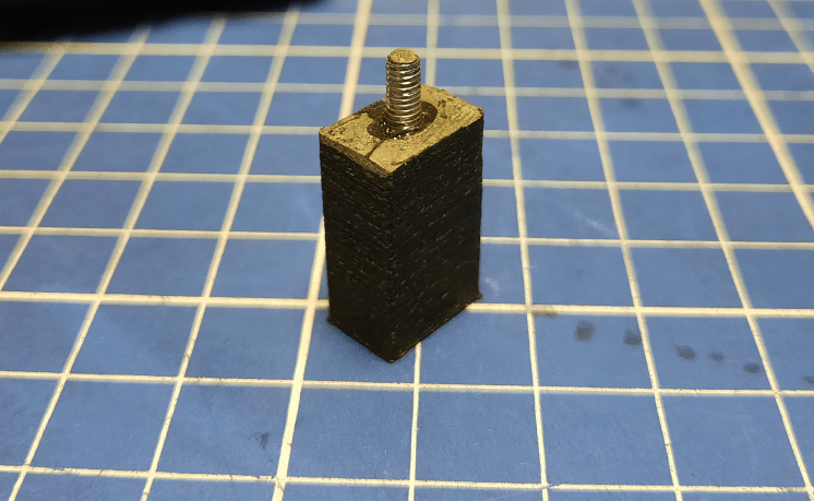
However, to hold it in place, I had to use a 3mm steel rod and a 3D-printed cube. I’ve utilized a hole that originally is used to solder the DB25 serial port socket on the motherboard as a locking spot.

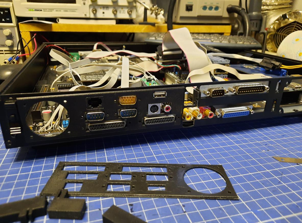
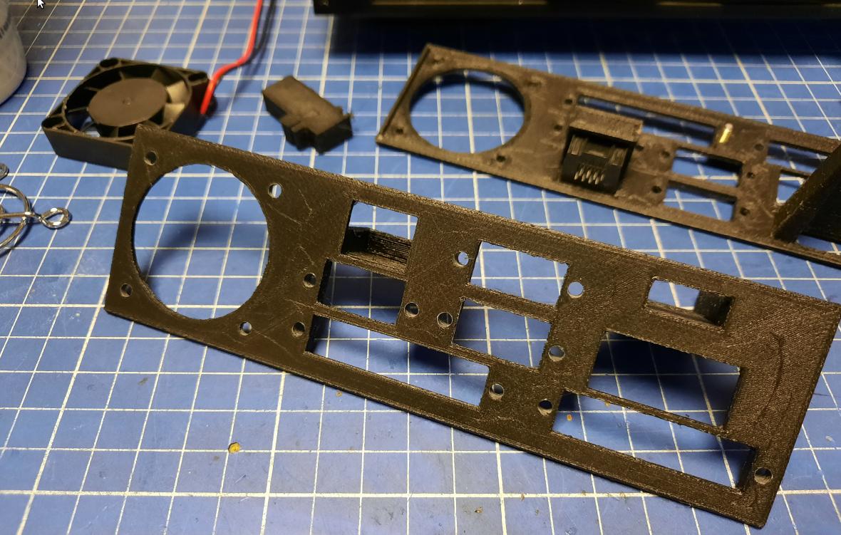
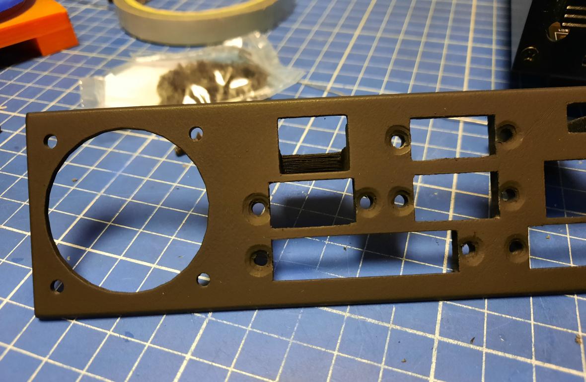
Post-processing the back panel printout
Finally, I had the first out of three parts of a back panel 3D printed. I could start working on it. I’ve ordered some black, flat-head screws and used a 10mm drill to create a space for screws to “sink in” a plastic part. The part was sanded and painted afterward.
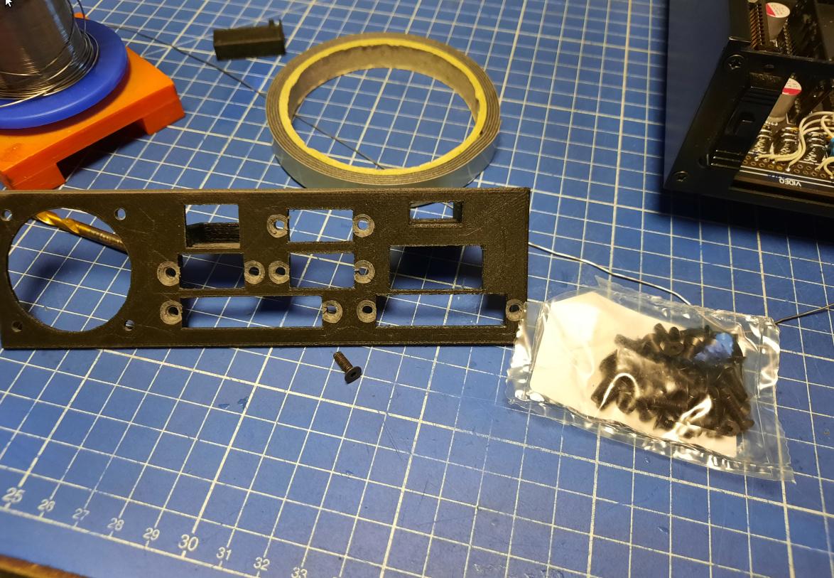
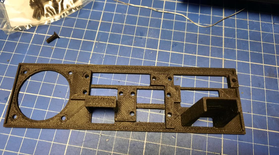
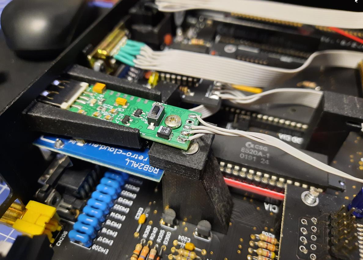
I also made a support stud for RGB4ALL.
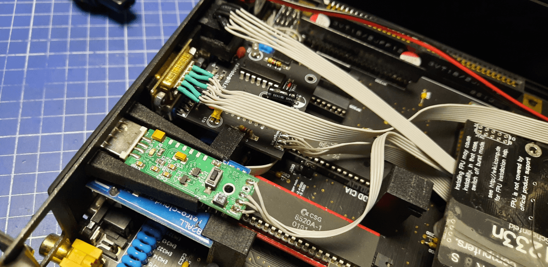
However, It wasn’t the best solution as it didn’t support the keyboard controller at all. That was changed in a second version 😉
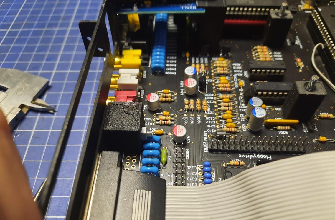
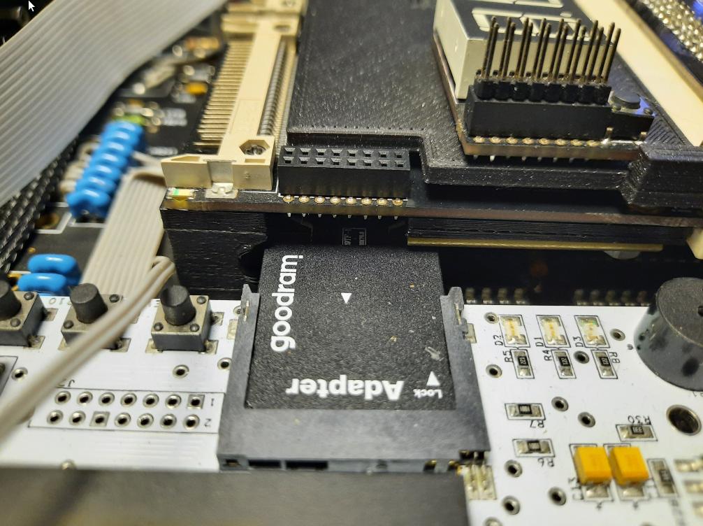
No, that screw is not shorting pins on the KB adapter ;P
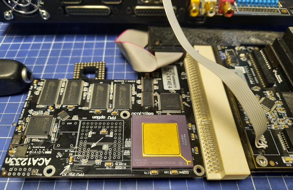
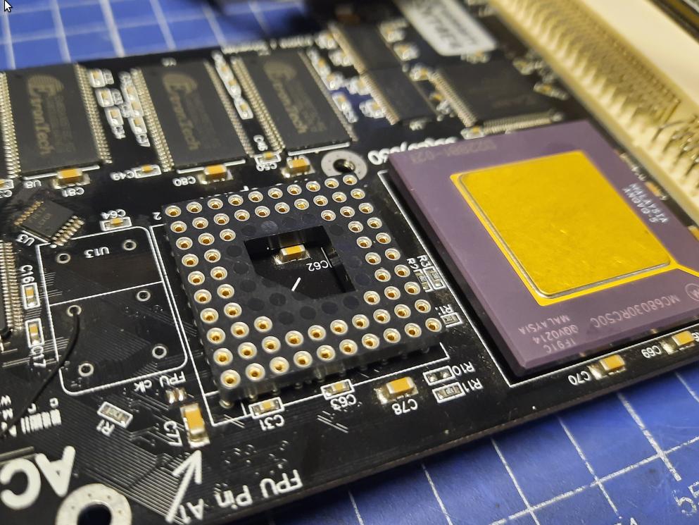
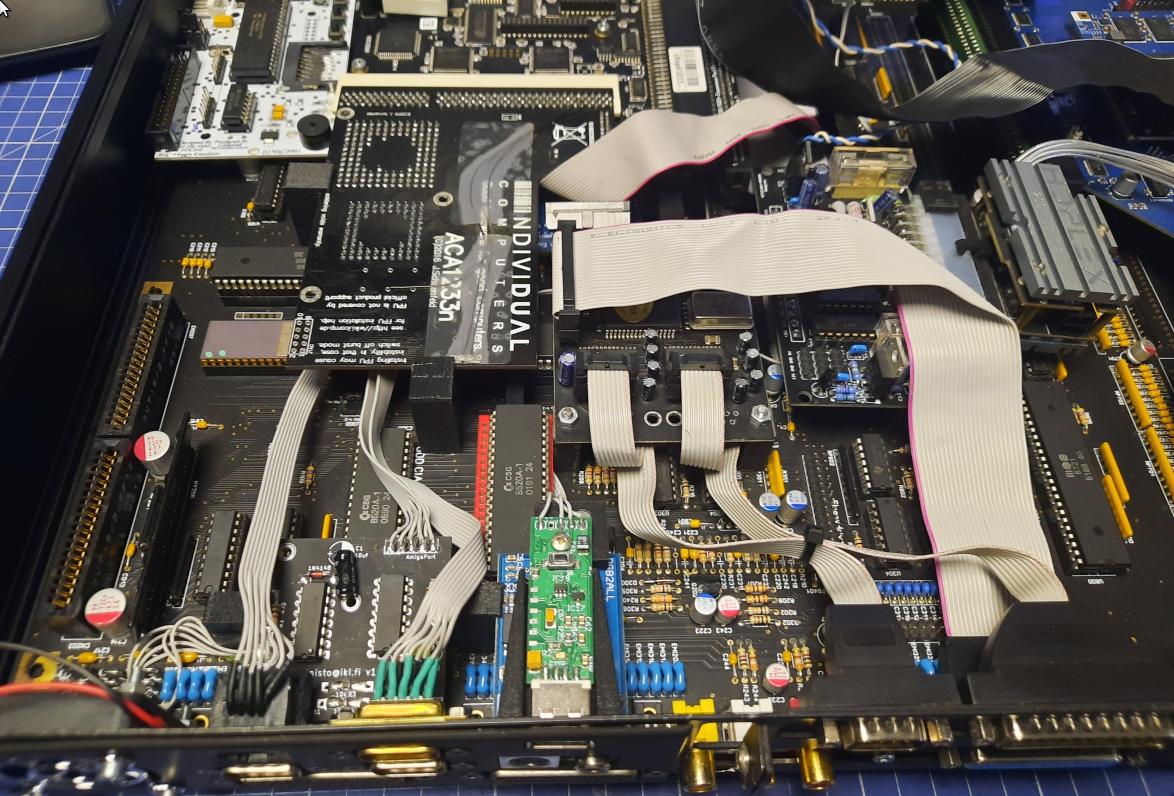
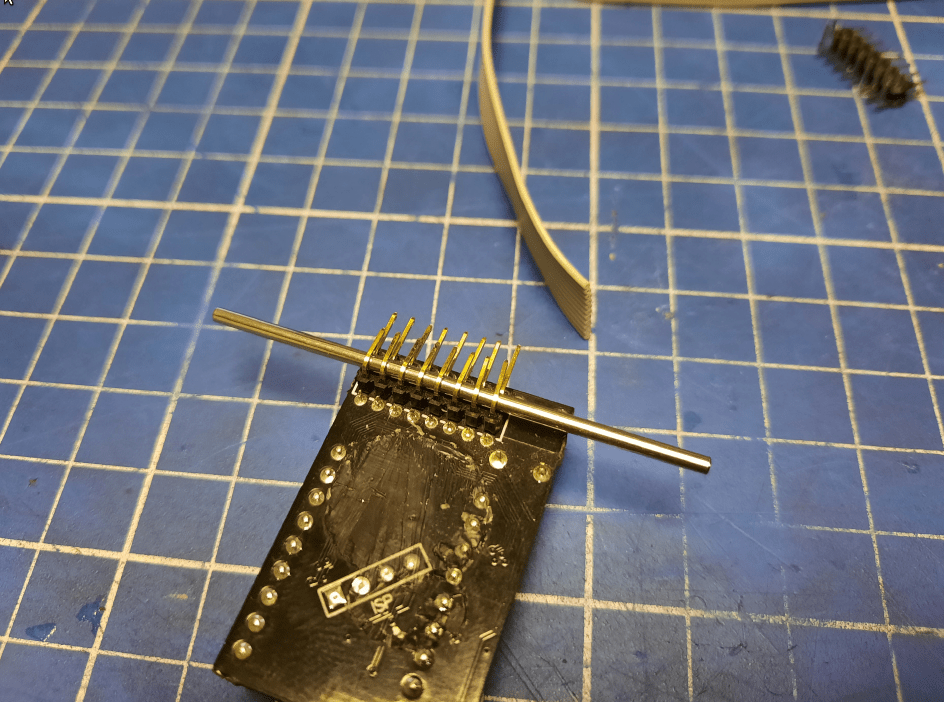
FPU socket – ACA1233n
The idea here was to install an FPU unit in an ACA1233n card to speed some tasks up. This is not a fully supported solution but … do we care at all? 😀
I didn’t have an FPU itself at that time. It was ordered but I was still waiting for delivery so pics of a socket only this time.
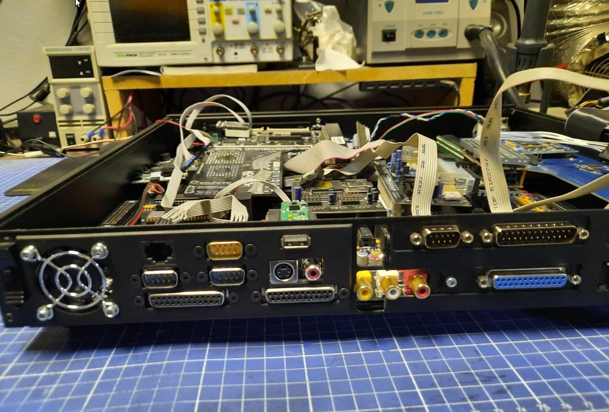
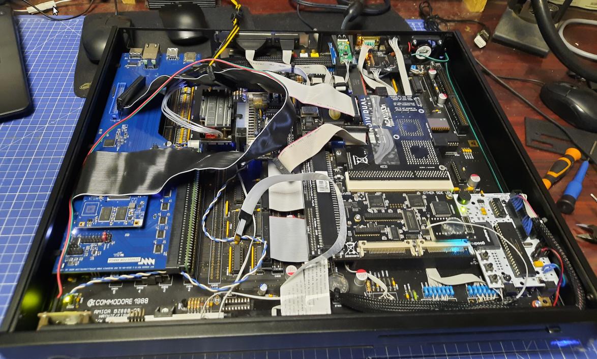
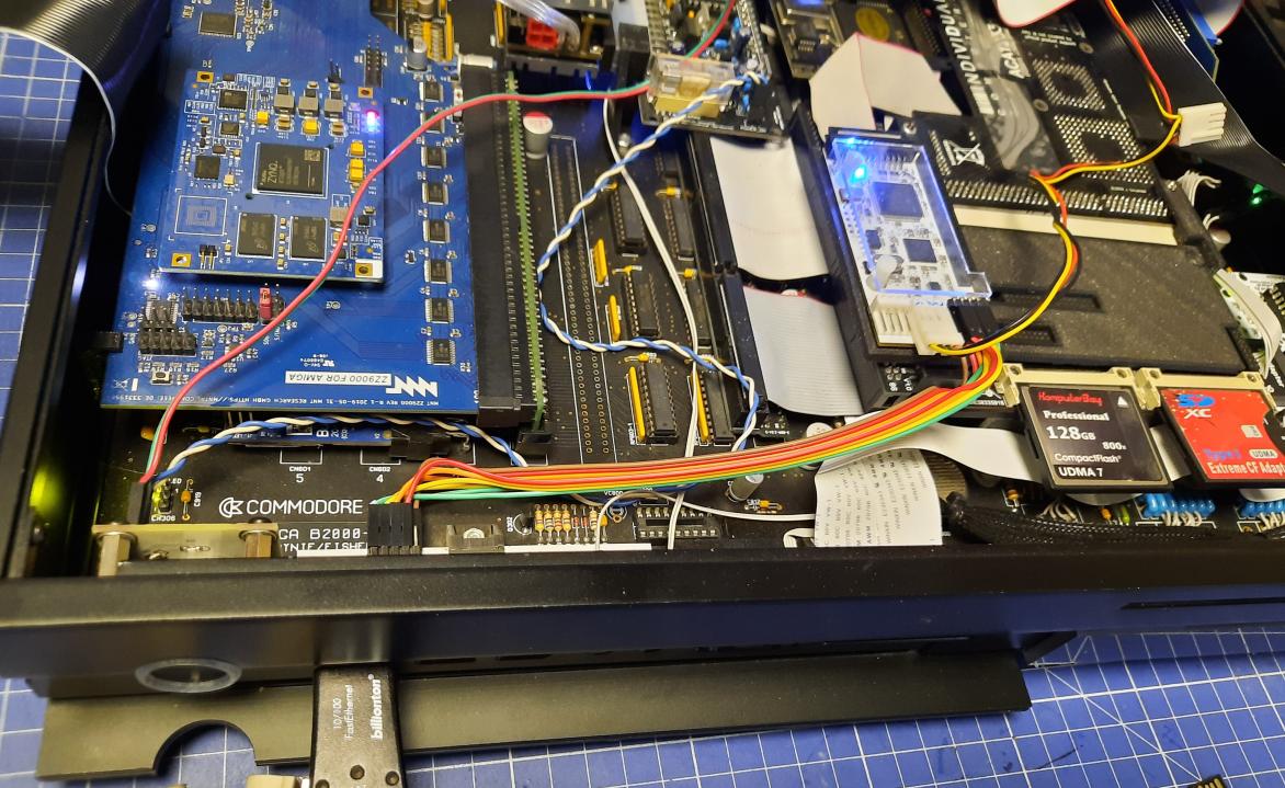
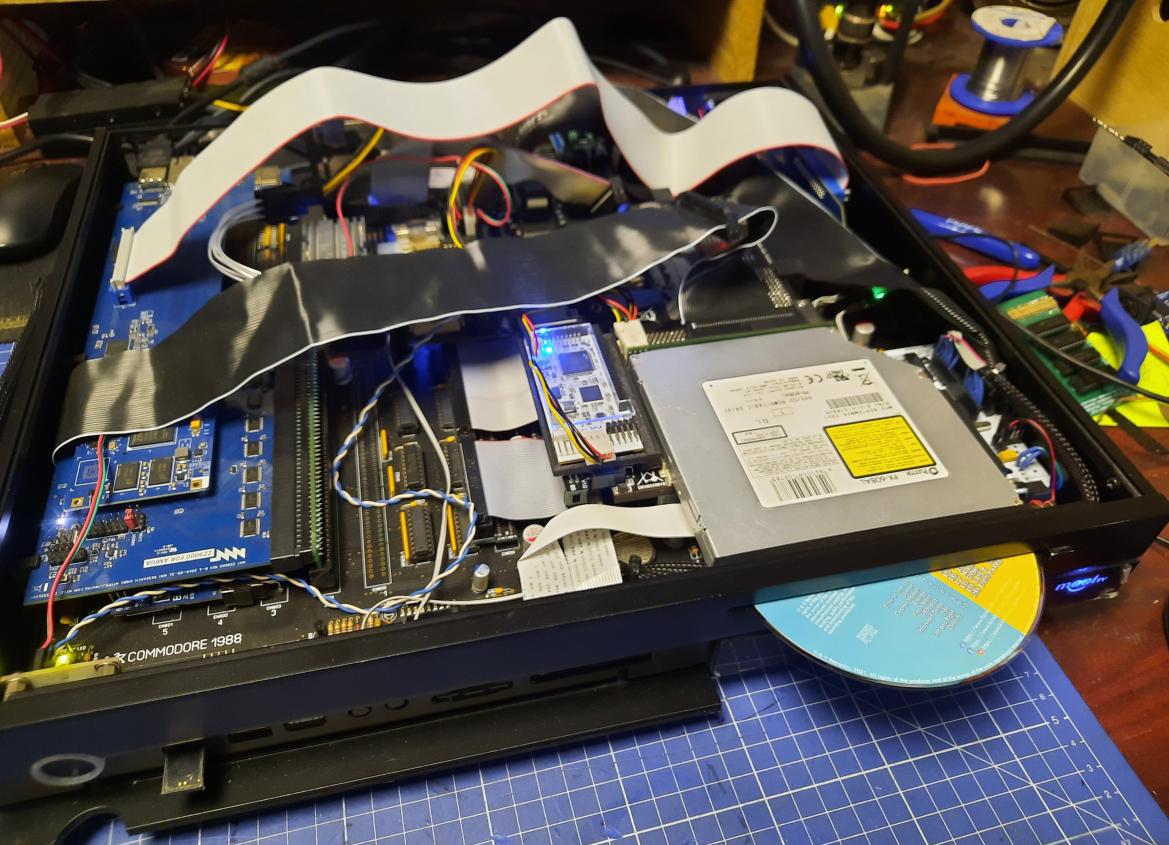
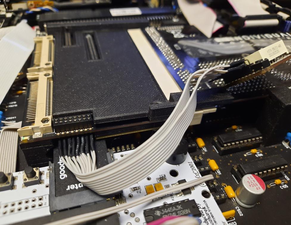
Mid-work cable management
Some pics of cable management that had to be done while the back panel was sorted out. Also, I’ve tested the layout of the other wiring that will be done in the future.
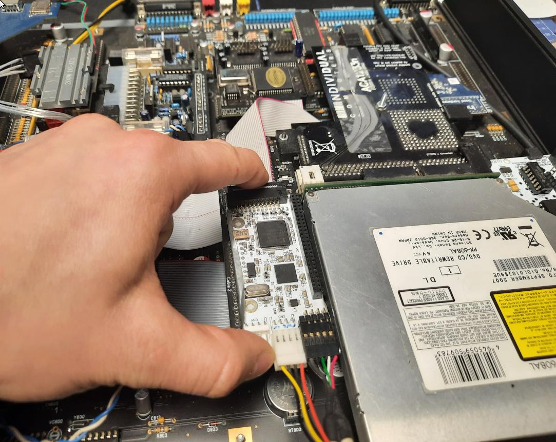
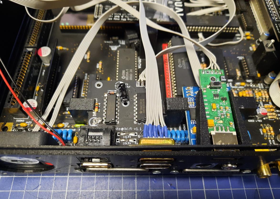
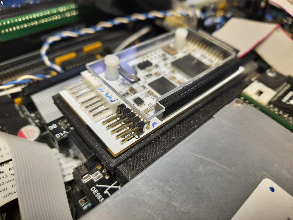
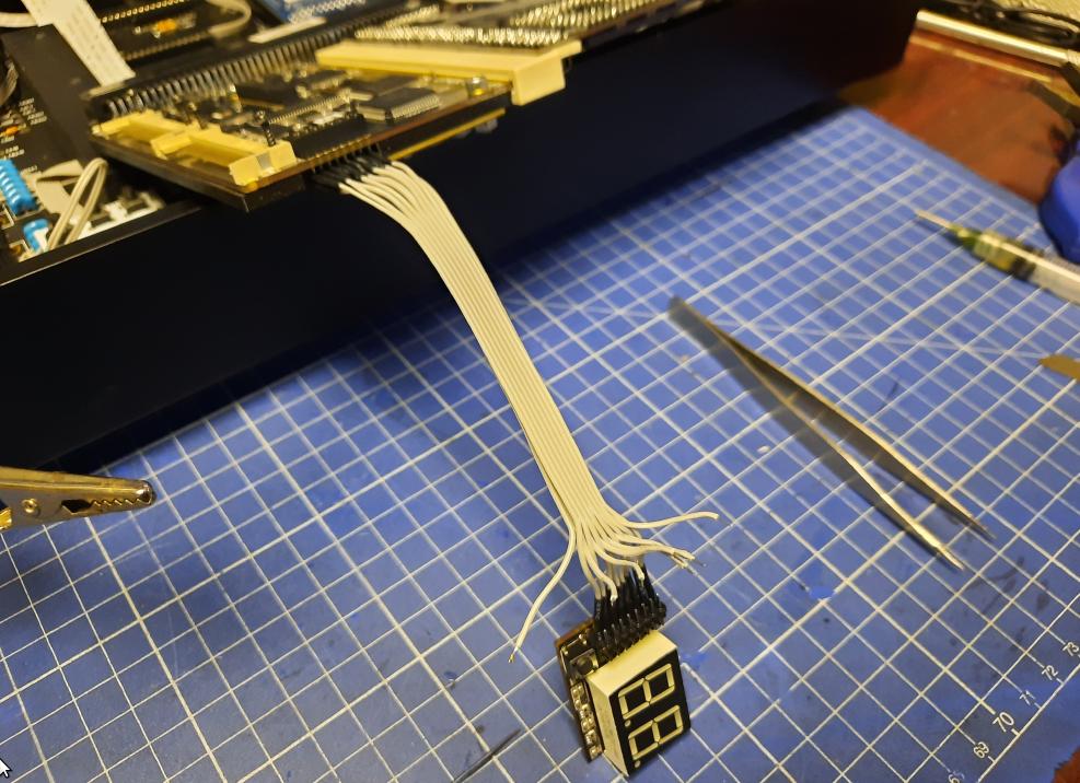
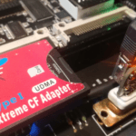
RapidRoad USB, DVD drive, HxC and DiSmo hax
The idea with the RR_USB mod was placing it just next to a DVDROM drive and this is because I was limited by the clockport ribbon wire length. Here is how I’ve solved this particular puzzle.
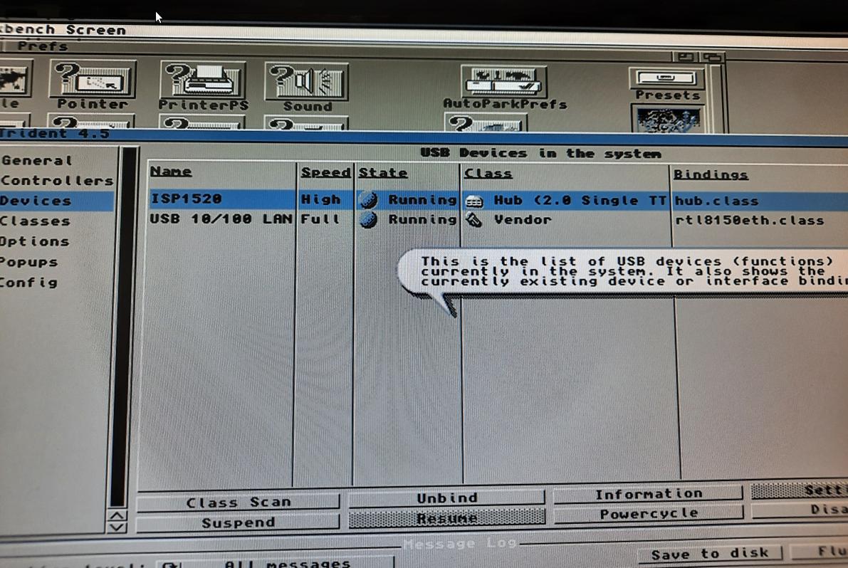
RapidRoad USB works! It successfully detected a USB LAN card and USB flash drive! YAY!
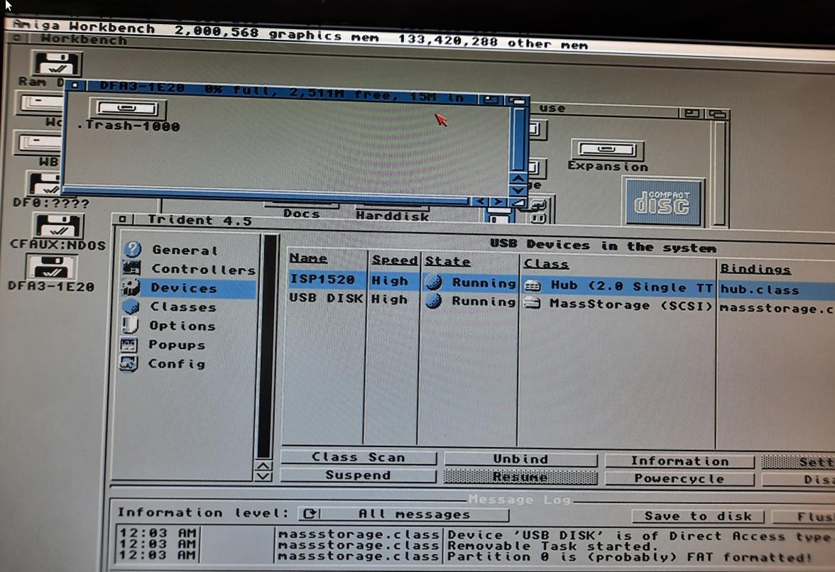
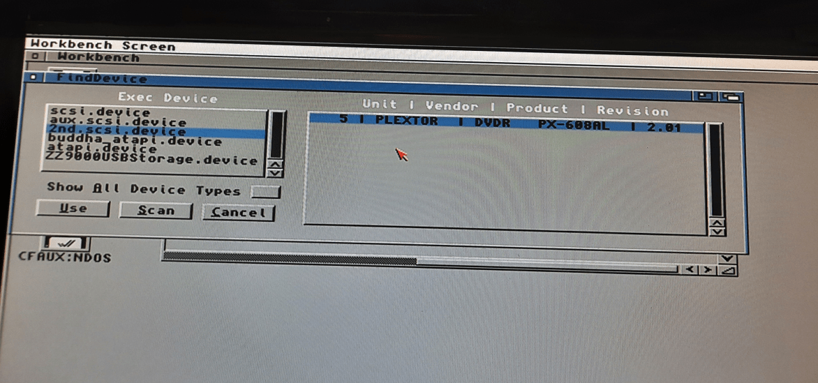
I’ve connected a DVD drive through the Buddha controller and ran some tests with RapidRoad USB plugged in next to it.
I will have to work with the software config as it was detected as a SCSI drive and not ATAPI so using CacheCDFS might be an issue if I am correct.
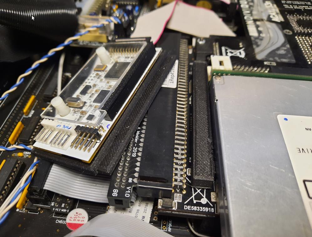
Some previously 3D-printed holders had to be slightly modified to accept SD card extenders for HxC.
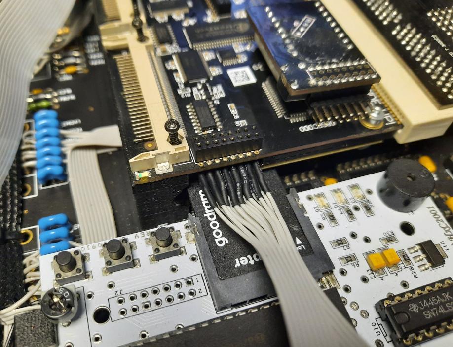
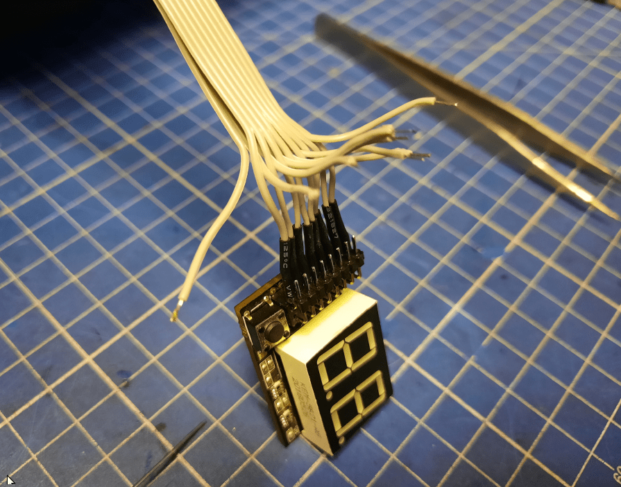
I also had to move DiSmo. It is originally mounted on an ACA500+ but in this configuration, it would face its LCD down (facing PCB) which is kinda useless. I’ve figured that I will add some wires and move it to a side, right above a HxC as I had some room at that spot. The last pic is not the final spot, it will be covered later. Here is what it all looked like.
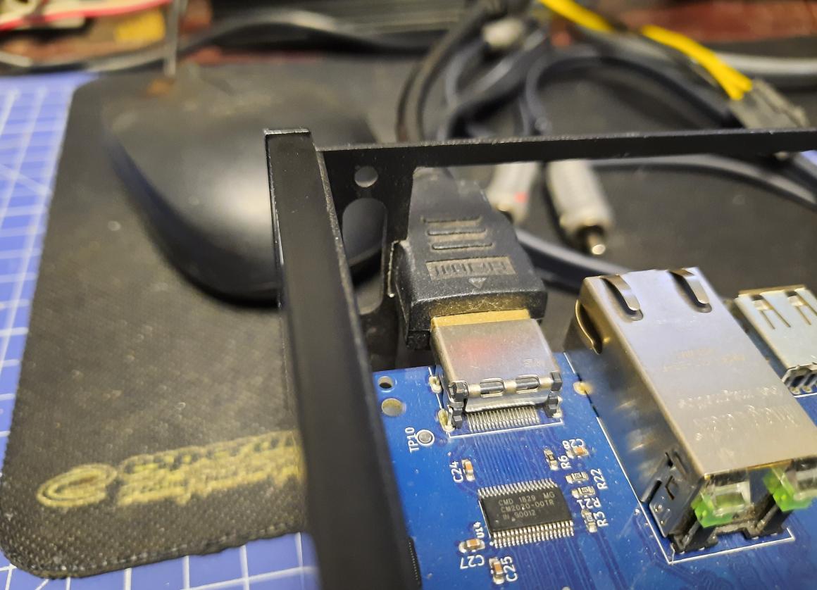
Case mod – ZZ9000 HDMI
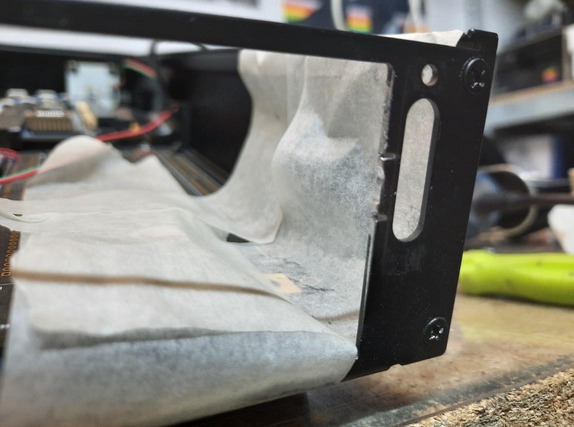
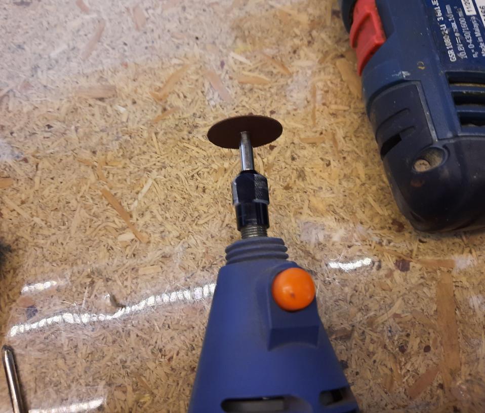
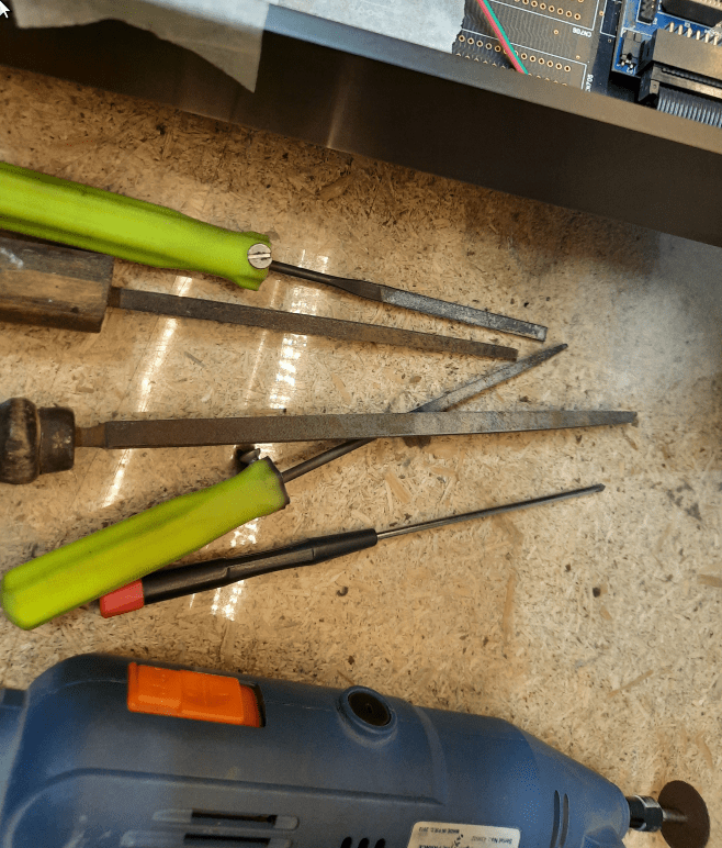
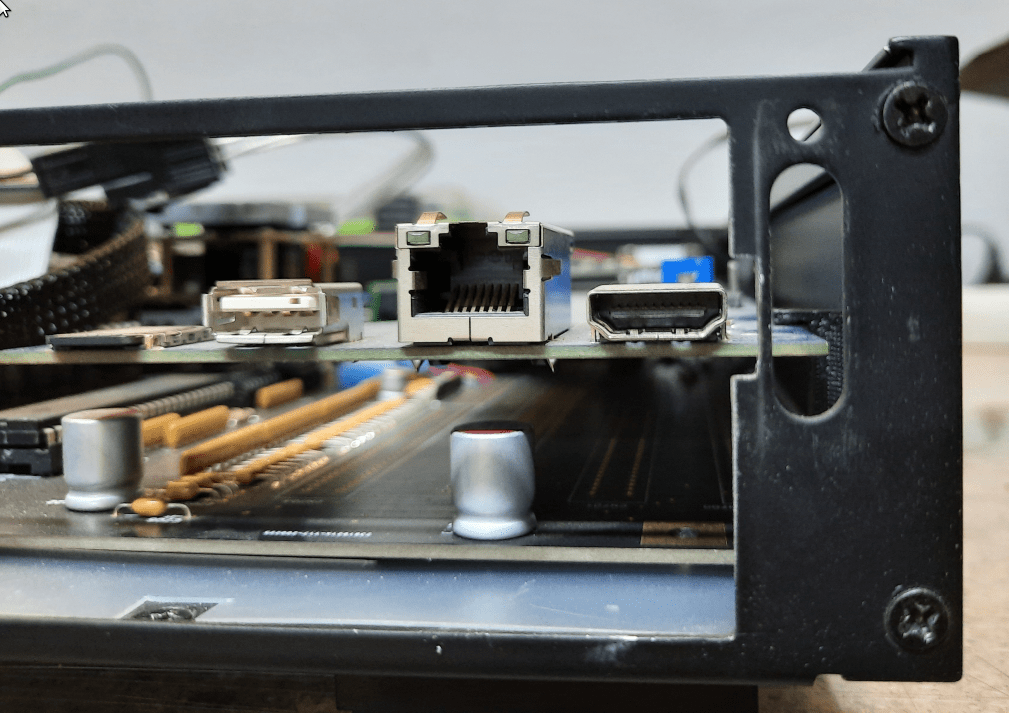
Unfortunately, I had to slightly mod a case to make some room for the HDMI plug that will go into ZZ9000 as it simply didn’t fit. I didn’t want to disassemble everything so I used painter’s tape to cover some parts and used a cutting tool along with a needle file to make it.
The end of part 5
Ok, you’ve reached the end of part 5 but no worries, It looks like there are going to be another two parts. I’ve just checked and I still have nearly 200 pics to cover. The last pic in this post is from April 2022. Meh … this project does not belong to the #SHORTS category 😉
Outro
If you want to get the retro gear I am manufacturing or hardware modules, please visit shop -> https://retrohax.net/shop/
Please support my work by commenting here and on our Facebook or Twitter pages.
It’s totally worth it.
The biggest challenge is that some parts can not be bought anymore.
Quite a usual problem in Amiga-land.
The ACA1233n is not available in that speed anymore. The replacement features a better, additional CF-slot but lacks the clockport.
High-speed serial interfaces are only available from second-hand markets.
The RTG graphics card ZZ9000 has pre-order times of 6-9 months.
Clockport-USB devices are only available from non-commercial sources (“Freeway CP”).
Clockport-audio devices are really rare even on second-hand markets.
so if someone were to want to buy one of your Drygol A2000 Tesseract computers, how much do you think it would be?
Parts costs are easy to count as we know the prices of add-ons and the rest. I didn’t count it though.
Funnily enough, I did a project summary (time-wise) two days ago and it turned out that it lasted for 2.5 years. If it is about time spent on it, it is 6.5 months of a full-time job.
As you can see, I would have to charge a lot if I was to work on it full-time. Dunno how much exactly but the time period should give you a base idea.