… or web spiders FTW!
<intro>
C64 fixing mayhem ended!
</intro>
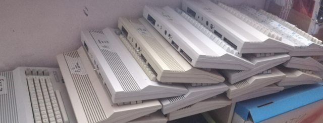
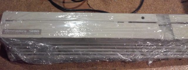
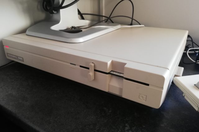
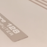
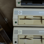
I always wanted to play with C128 DCR. This is a cool machine since it has all in one case – a desktop case.
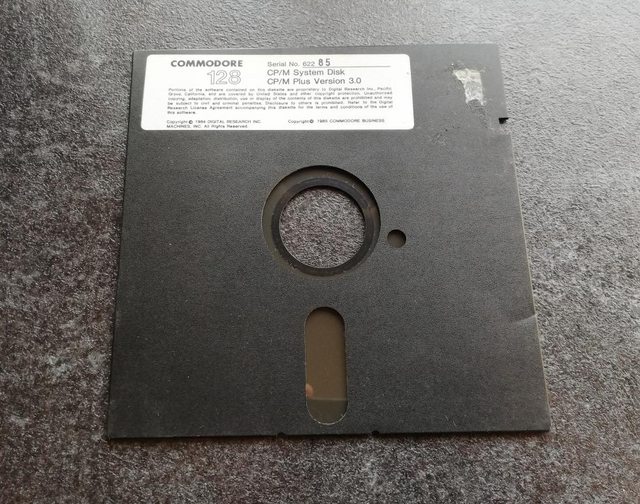
It can work in three modes – C128 mode natively but can also boot to C64 mode and with a proper disk it can run CP/M software under its second processor Z80!
I’ve got one such machine. It was bought as “For parts not working” … as usual. Buying working hardware isn’t fun, is it? 😀
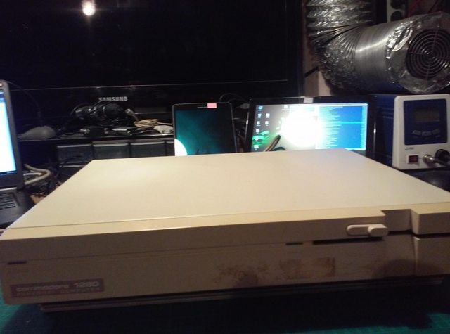
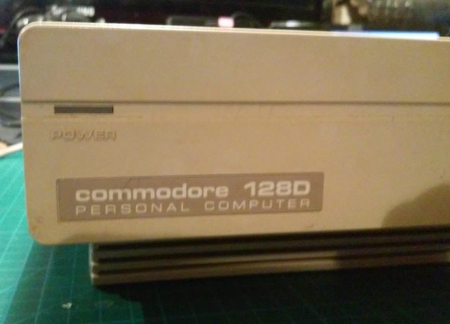
It even had an original seal!
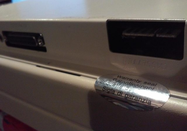
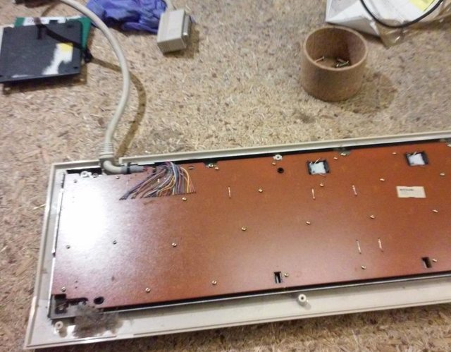
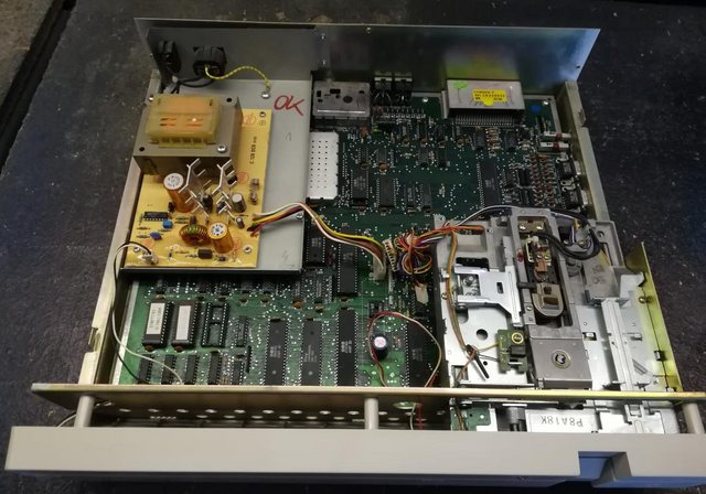
The disassembly process started and almost instantly I knew what will require fixing.
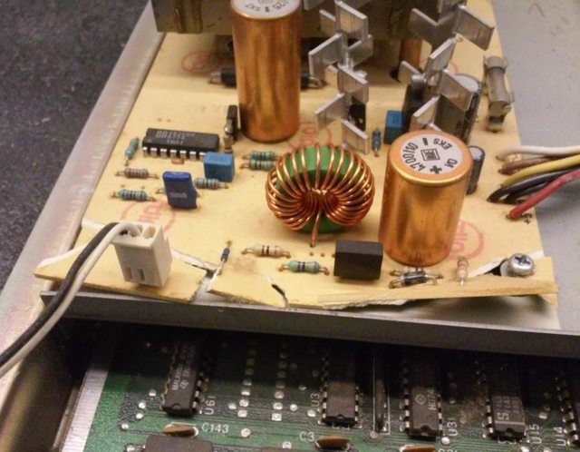
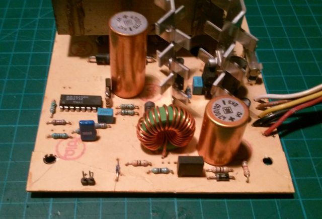
Internal PCB of power supply was shattered. I was really surprised because this C128D had an original warranty seal on it, so how would one manage to brake it without opening it?
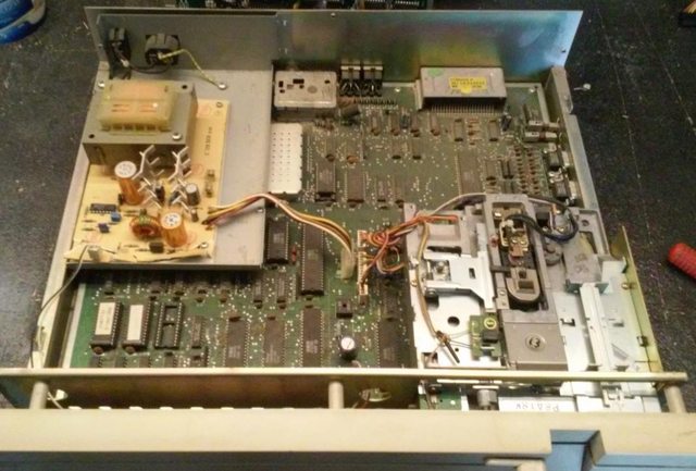
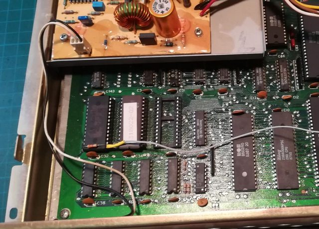
A PCB was a bit dusty but it didn’t show any problems at first sight.
Lolz
Now to a major lol in this post 😀
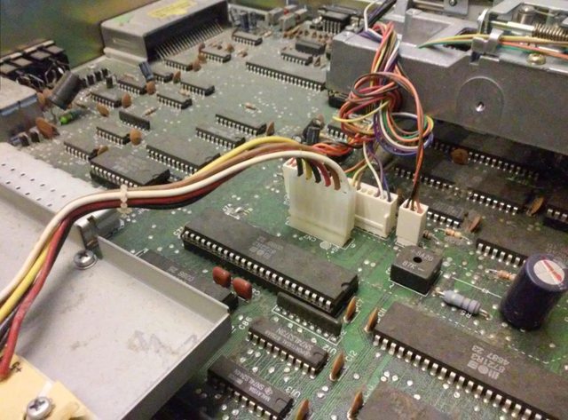
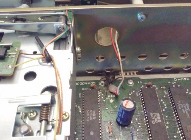
I was taking some pics while inspecting this motherboard and this is what I’ve found …
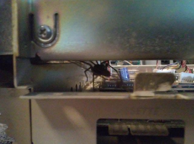
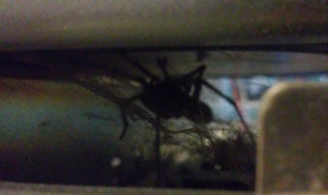
I was like WTH!!! At first, I thought it was dead and dried up … except for the fact … it wasn’t! lol!
Well, I’ve told him that I am sorry that I am taking away his home but since it was nice weather, I’ve taken it outside and showed him a nice spot for a new one. Hopefully, he is still there, hunting for mosquitos and flies lol 😀
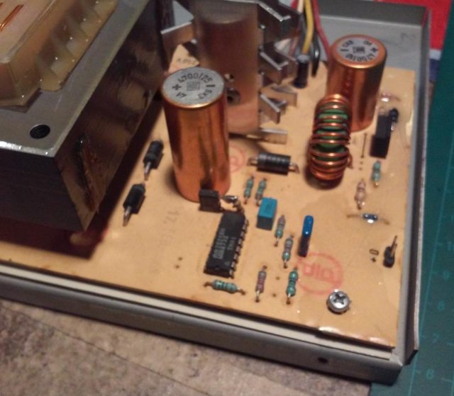
Anyway, back to work. Internal PSU had to be fixed as the first thing to check if a machine works.
PSU
Puzzles time! 🙂
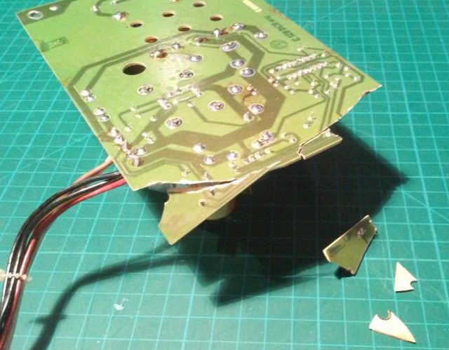
The PCB is an FR2 type, so I’ve used cyanoacrylate glue to temporarily put it together.
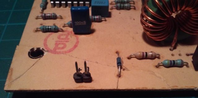
Once that was done, I poured epoxy resin on top to make it rock solid. I wanted to cover the largest possible area while avoiding more complex parts so only resistors and diodes were covered.
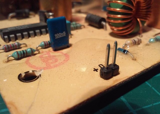
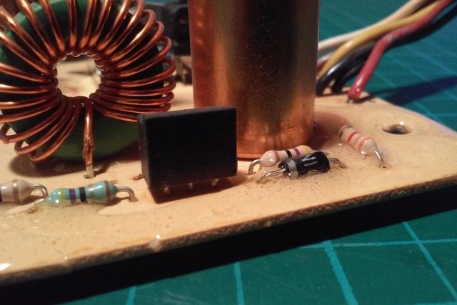
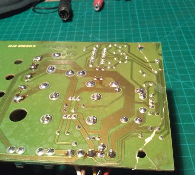
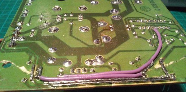
With a PCB in a one-piece, I’ve started to remove the solder mask on the bottom part traces to prepare it for soldering.

Then, I soldered on wires that connected all broken traces. At this point, I’ve also fixed several cold joints that were there too.
With all the above done, I’ve mounted PCB back onto its chassis.
The moment of truth aaaaaaand…
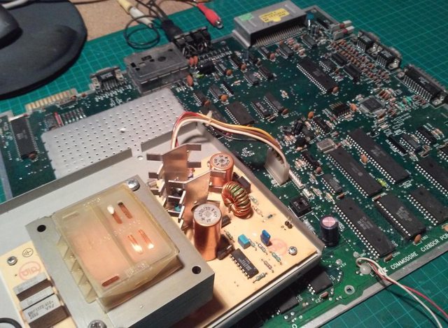
It worked!! 😀
Keyboard
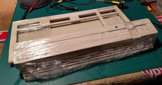
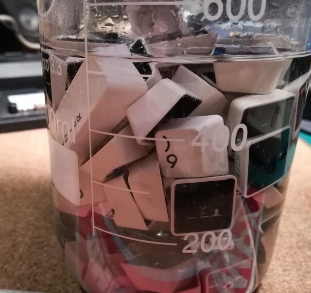
Ok, so when I knew it works, I could continue with refurbishing. As usual, I’ve disassembled the keyboard, cleaned it off, and retr0brighted it along with the rest of the case.
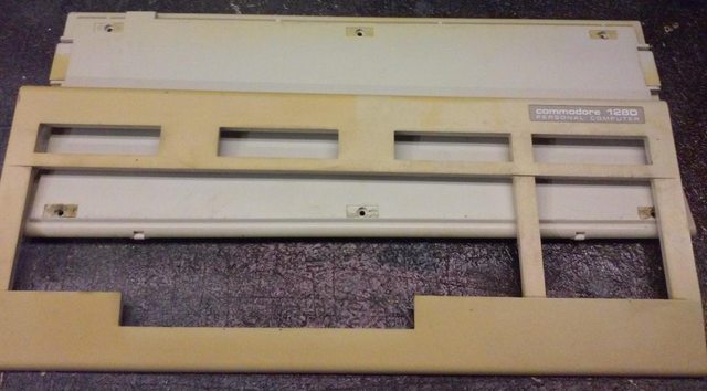
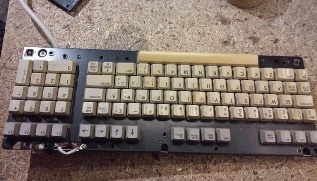

The results were more than satisfying.
JiffyDOS
Now, with everything in place, I could start working on a JiffyDOS mod.
You can get JiffyDOS on a Retro Innovations website.
I still have a lot of blank Winbond 27C512 flashrom chips so for my mod, I’ve decided that I will need only an image and will burn it into flashroms myself.
At first, I thought that I will need two flashroms, like in a flat C128.
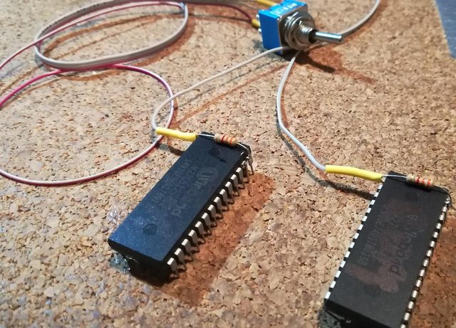
However, It turned out that C128D uses only one socket for ROMs so I had to rebuild my ROM image chain and burn it all again to a single chip.
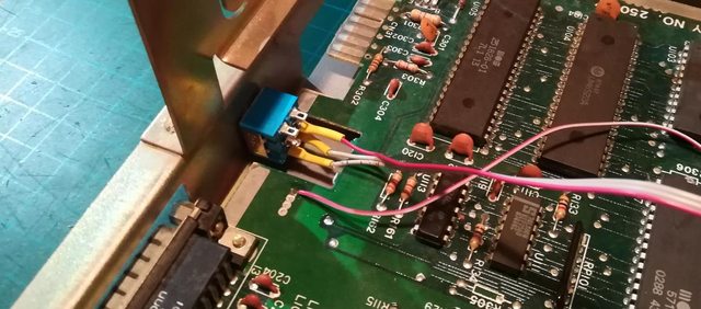
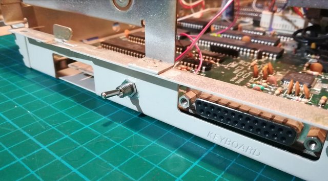
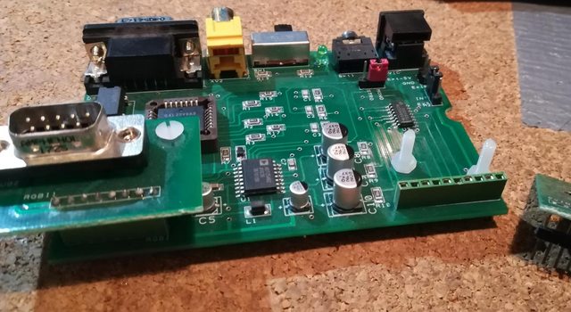
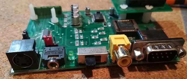
I’ve put a switch on a side of a case, next to a keyboard connector.
Video add-on
I’ve also connected a nice device made by Pyrofer already covered in a post with C128 mods. In short, It allows using 80COL mode via S-Video.
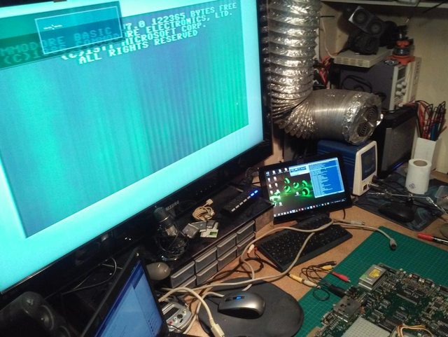
Finally some tests 🙂
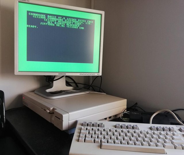
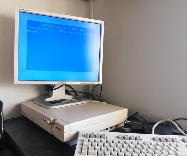
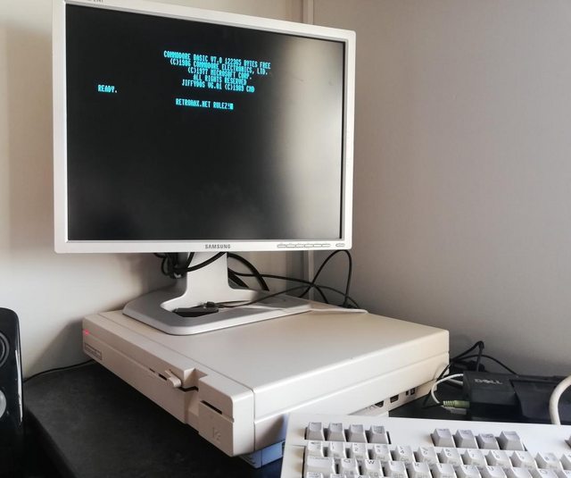

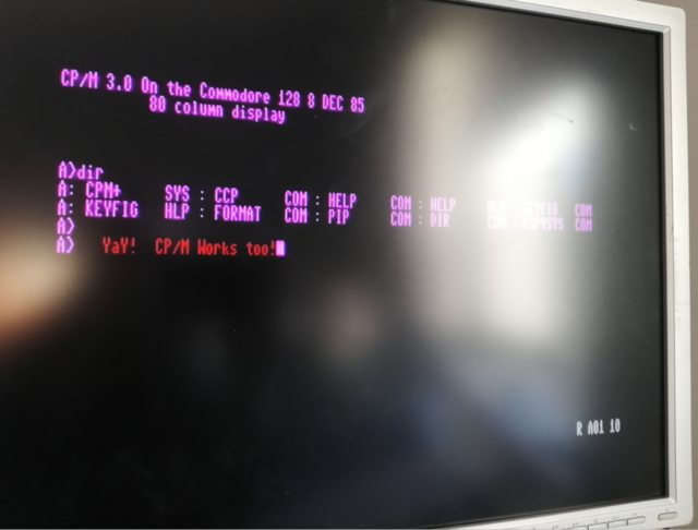
That’s it! I finally have a working C128 DCR!

OUTRO
If you want to get retro gear or hardware modules, please visit our shop -> https://retrohax.net/shop/
Also, please support our work by spreading info about it.
Without your support, we simply cannot grow and we have a lot of new cool retro hardware (and more) products to come 🙂
Nice look at that D C R C128 repair, mine has worked fine for years, but just bought springs to rebuild the keyboard from you,thanks.I’m also restoring a C64C, and flat C128
Great stuff! good to hear another machines are being fixed and used! ;D
Cracked PCBs were quite common on electronics back in the day. Those heavy transformers could easily crack a PCB if handled without care.
Indeed! I was just really surprised 😀