… or bashing the wall again :/
Intro

Welcome to another episode of the Commodore floppy drive fixing chaos. The first episode was described a long time ago and I promised there that I will revisit some issues in the future. Well, the future came … and it is not so bright 😉
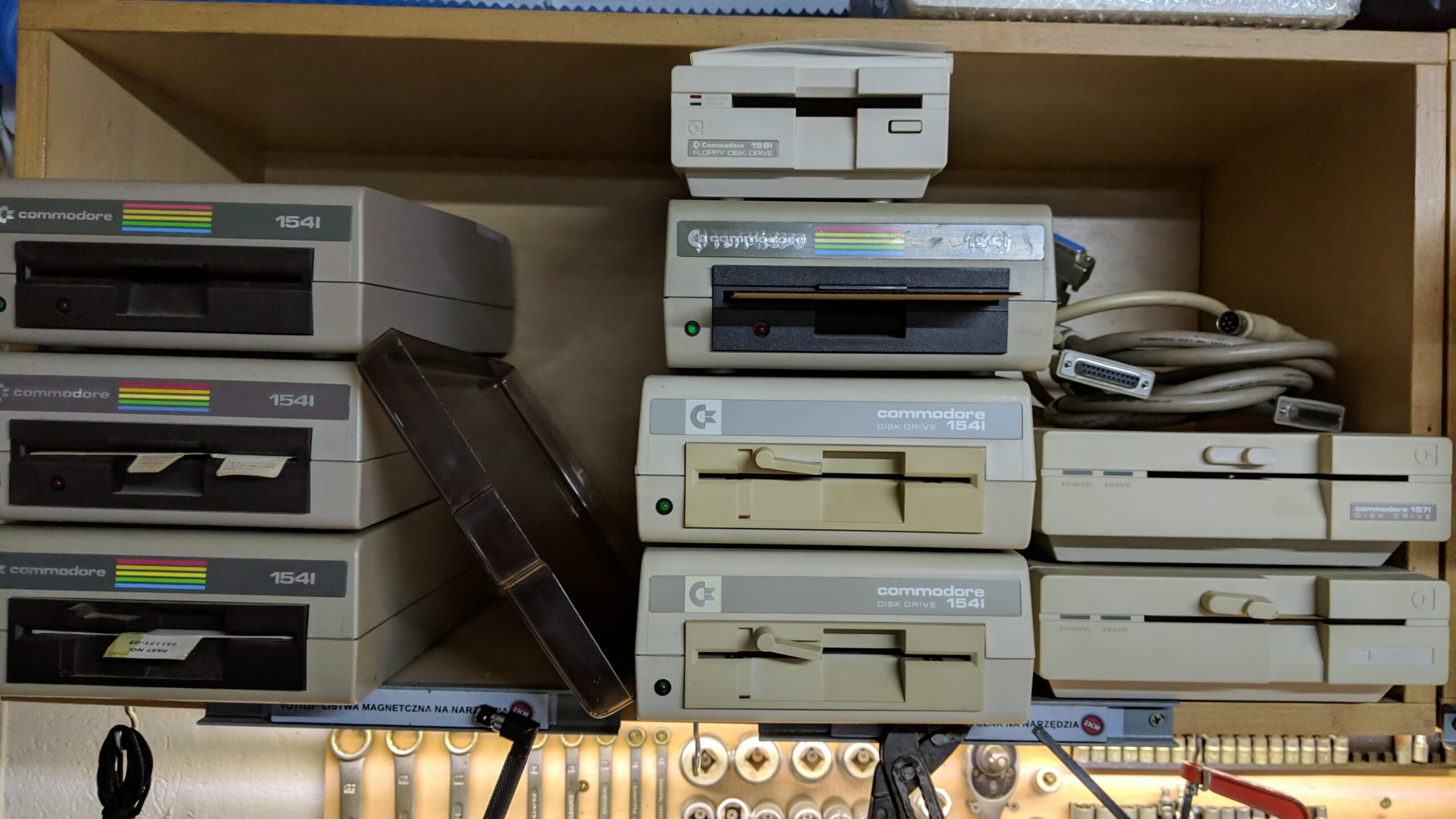
This time, I have some different types of Commodore drives. The goal is to fix as many as possible.
Today, I am addressing the following drives:
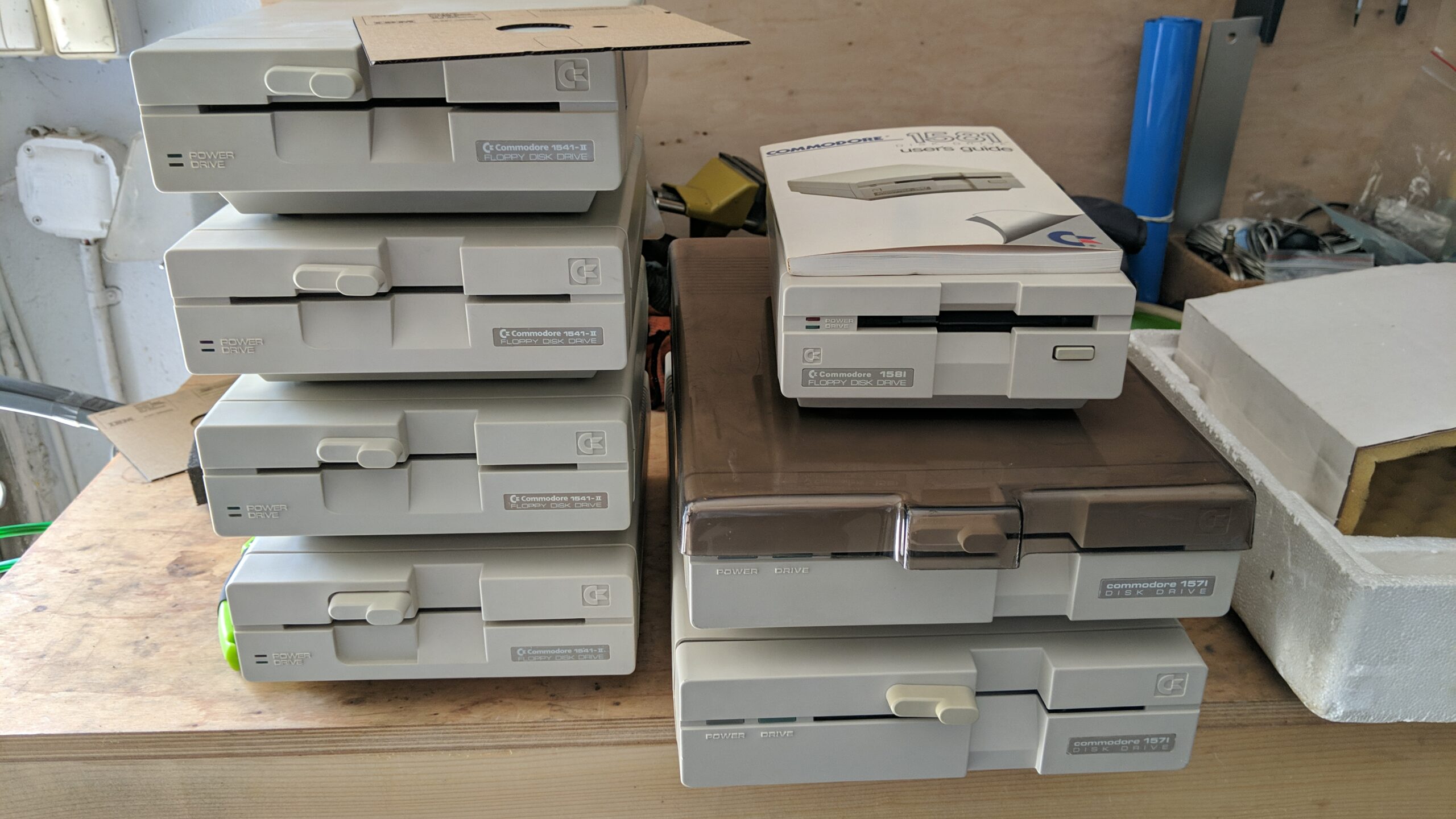
- 5x Commodore 1541-II
- 2x Commodore 1571
- 6x Commodore 1541
- 1x Commodore 1581
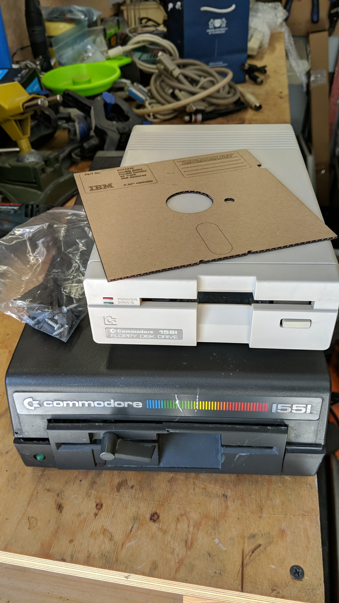
Well, there is also a 1551 but this is kinda extreme and deserves a separate blog post 😉
The procedure is a standard one. I needed to clean everything, retr0bright all cases, fix electronic issues, re-cap, lubricate and calibrate the drives. As there are quite a few of those drives, I will limit pics to the ones that are a bit more interesting. Let me start with 1541-II
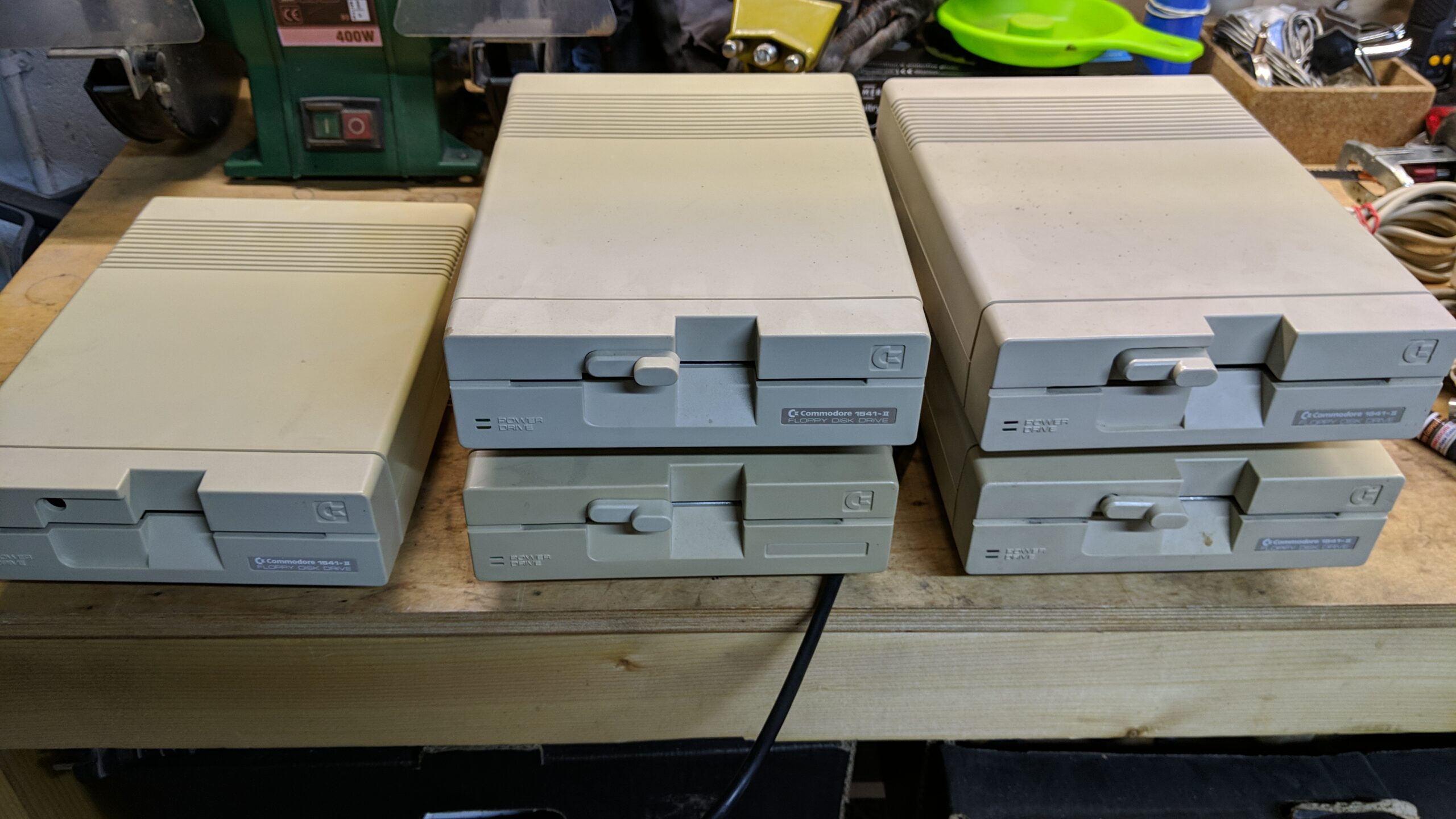
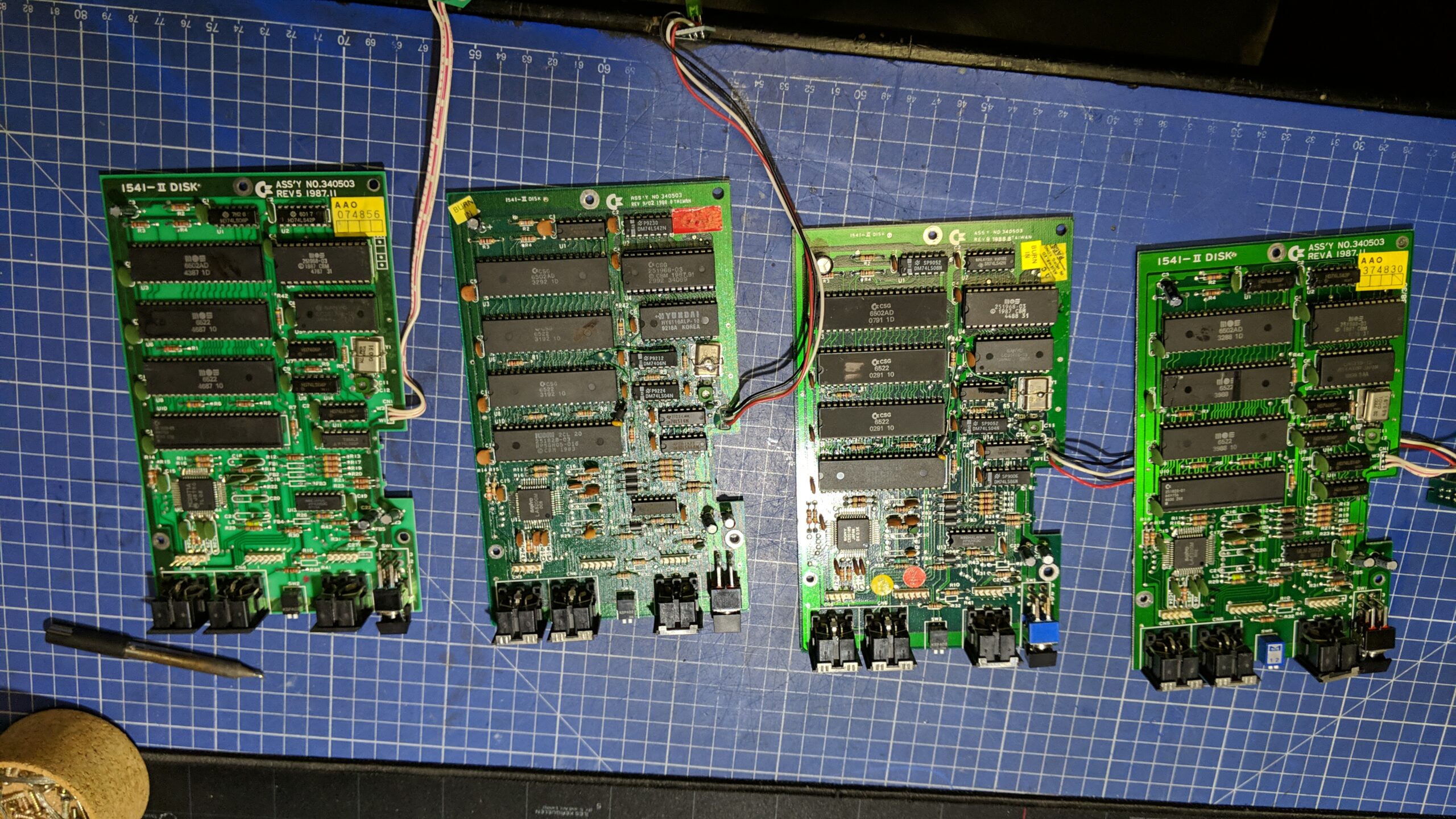
4x 1541-II
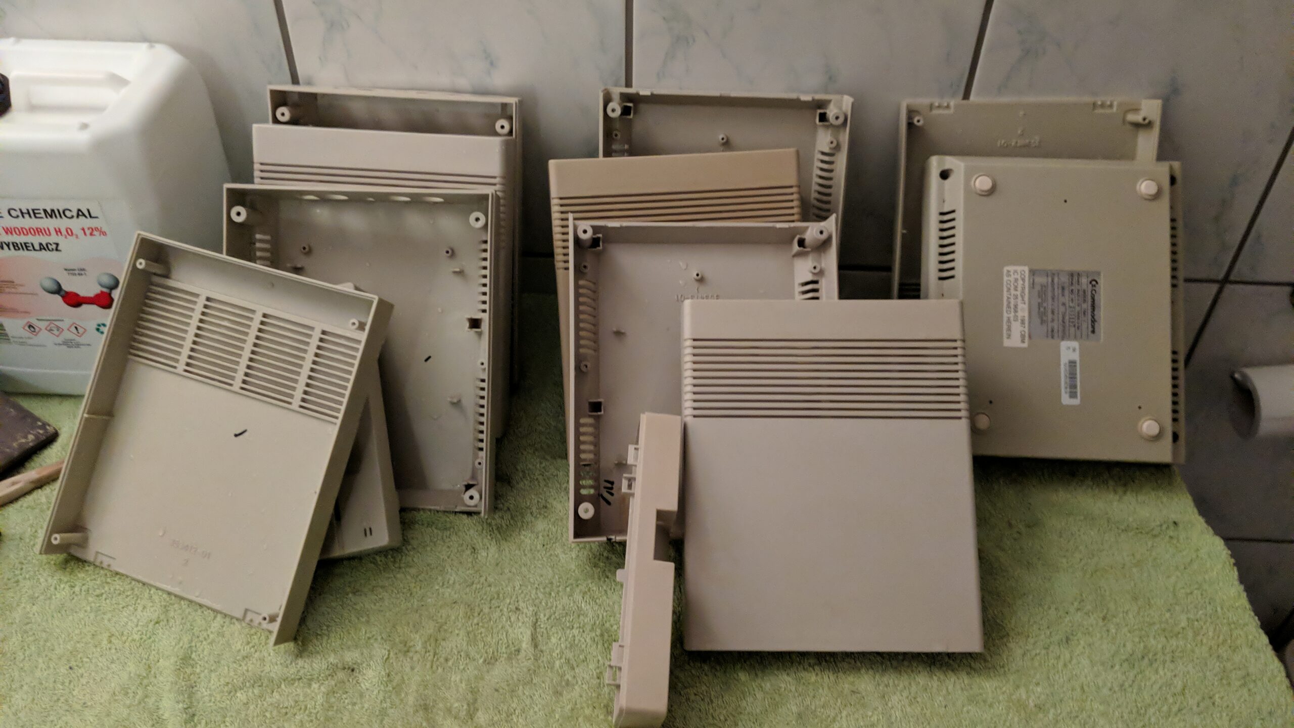
As usual, I’ve started testing and all four drives worked but some were out of alignment. I could proceed with disassembly and cleaning off the cases to prepare ’em for retr0brighting, though.
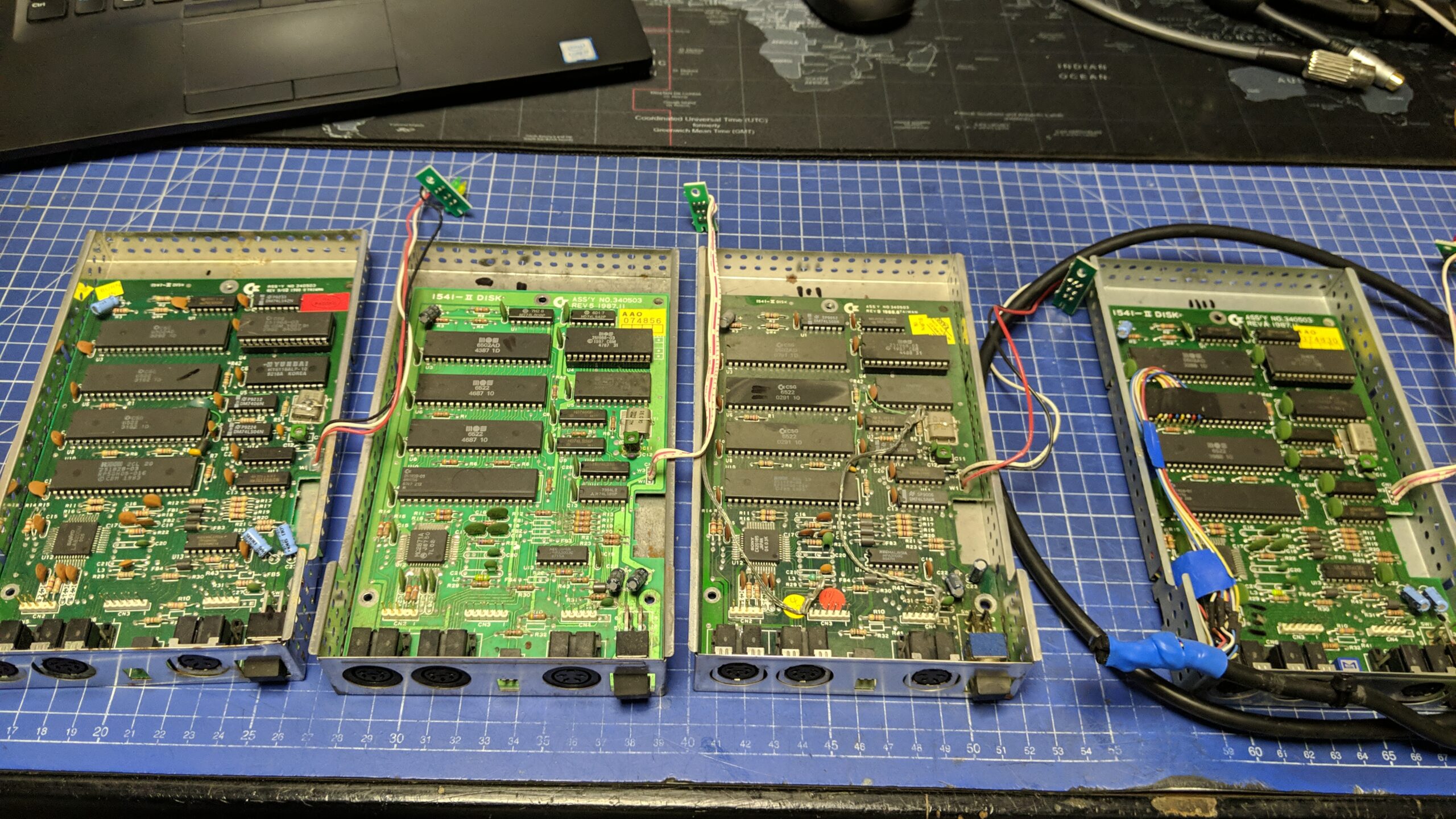
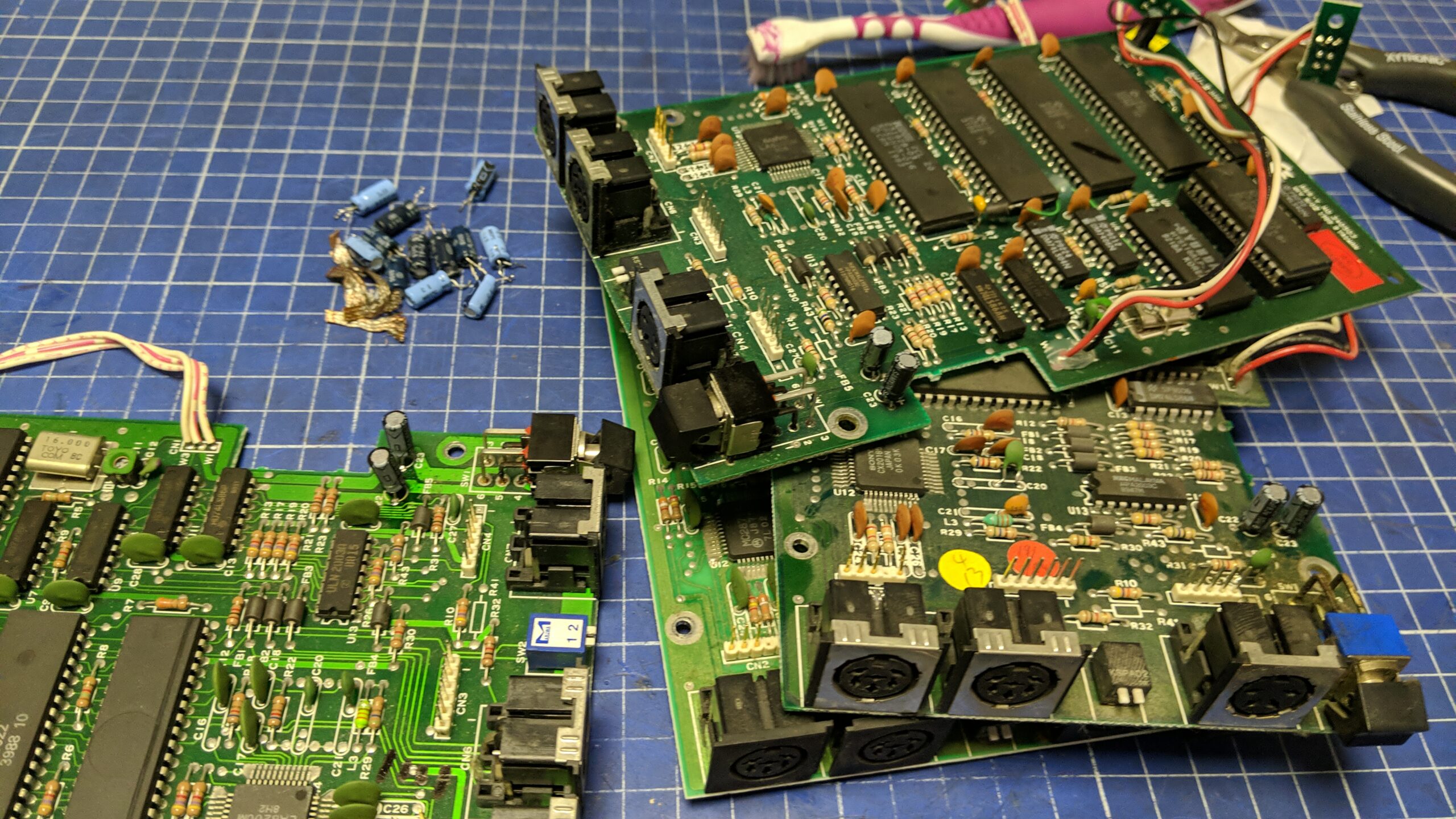
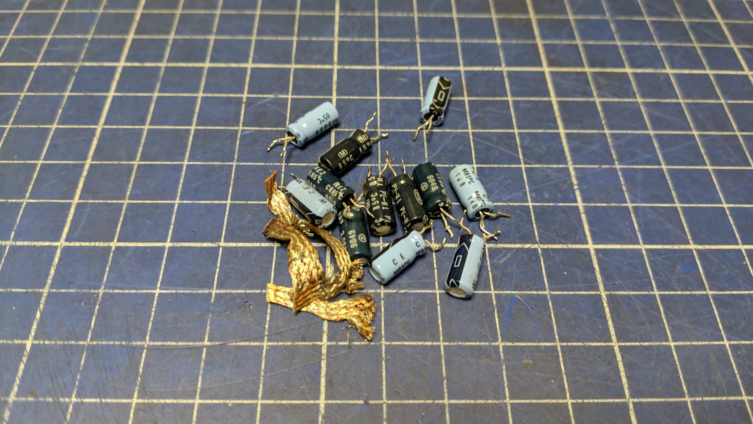
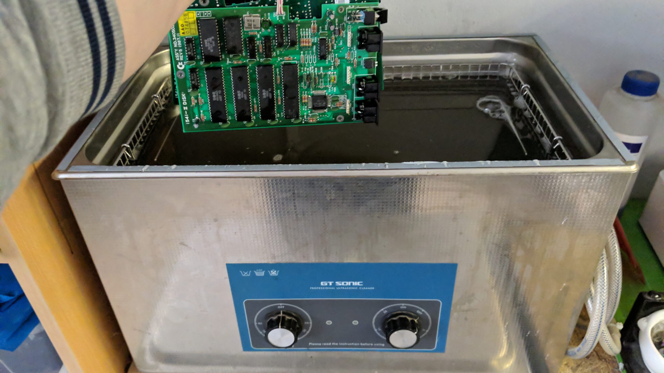
Next, all the PCBs were recapped and went through an ultrasonic bath.
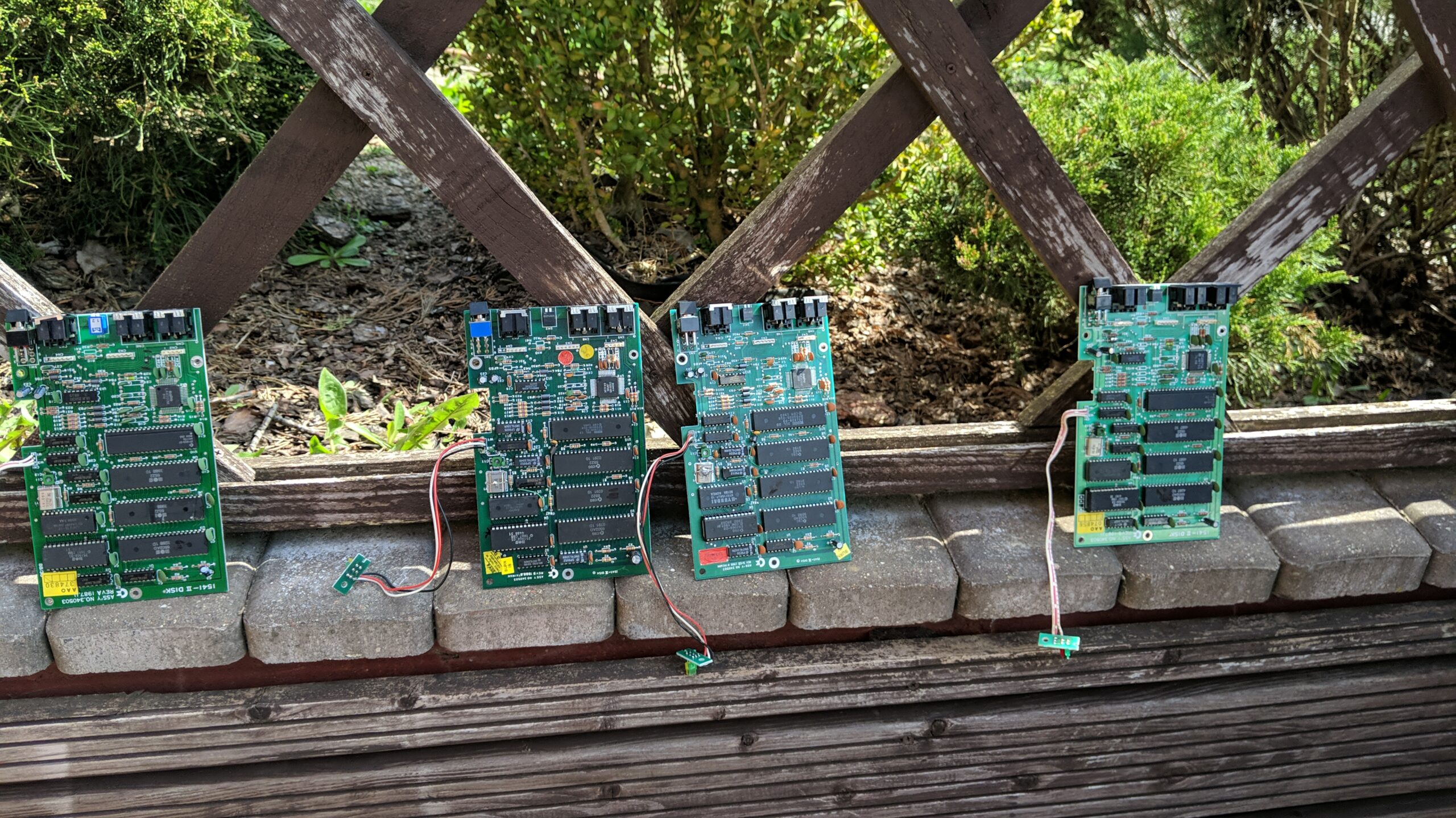
After a bit of sunlight, the boards were ready to go back in cases.
Meanwhile, the cases were ready after retr0brighting so I could start assembling it all back and start with drive cleaning and calibration.
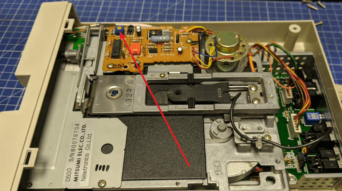
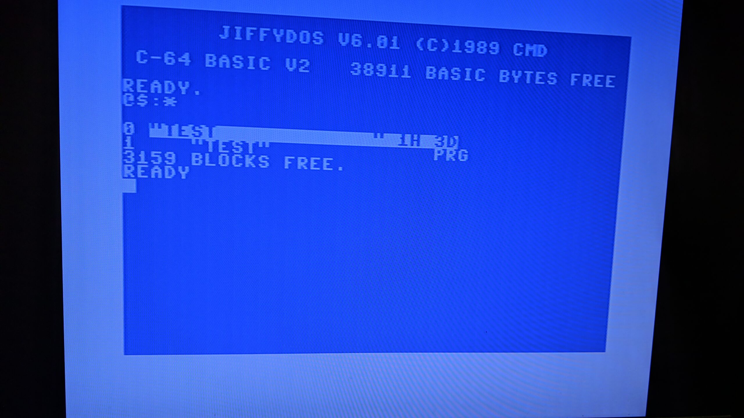
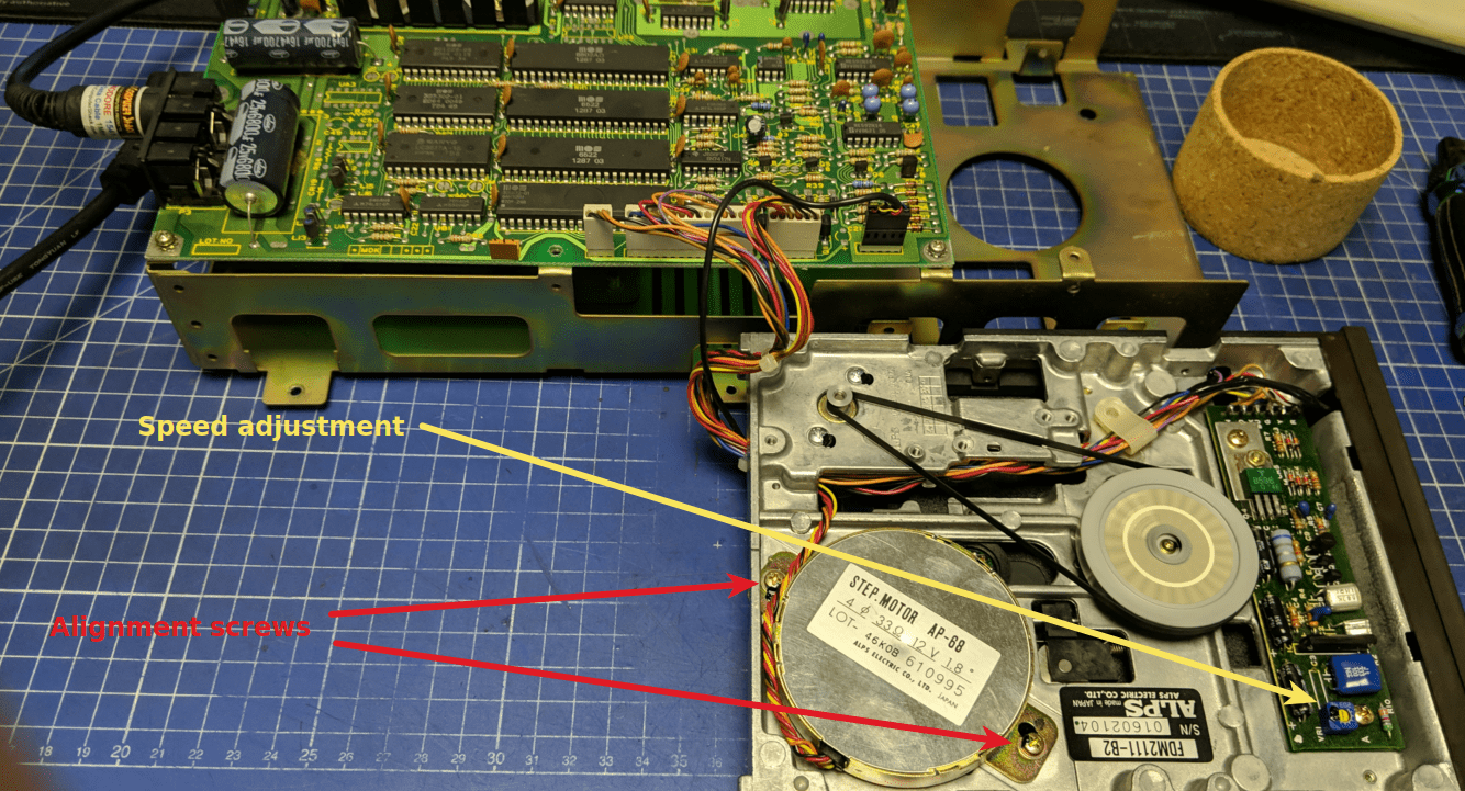
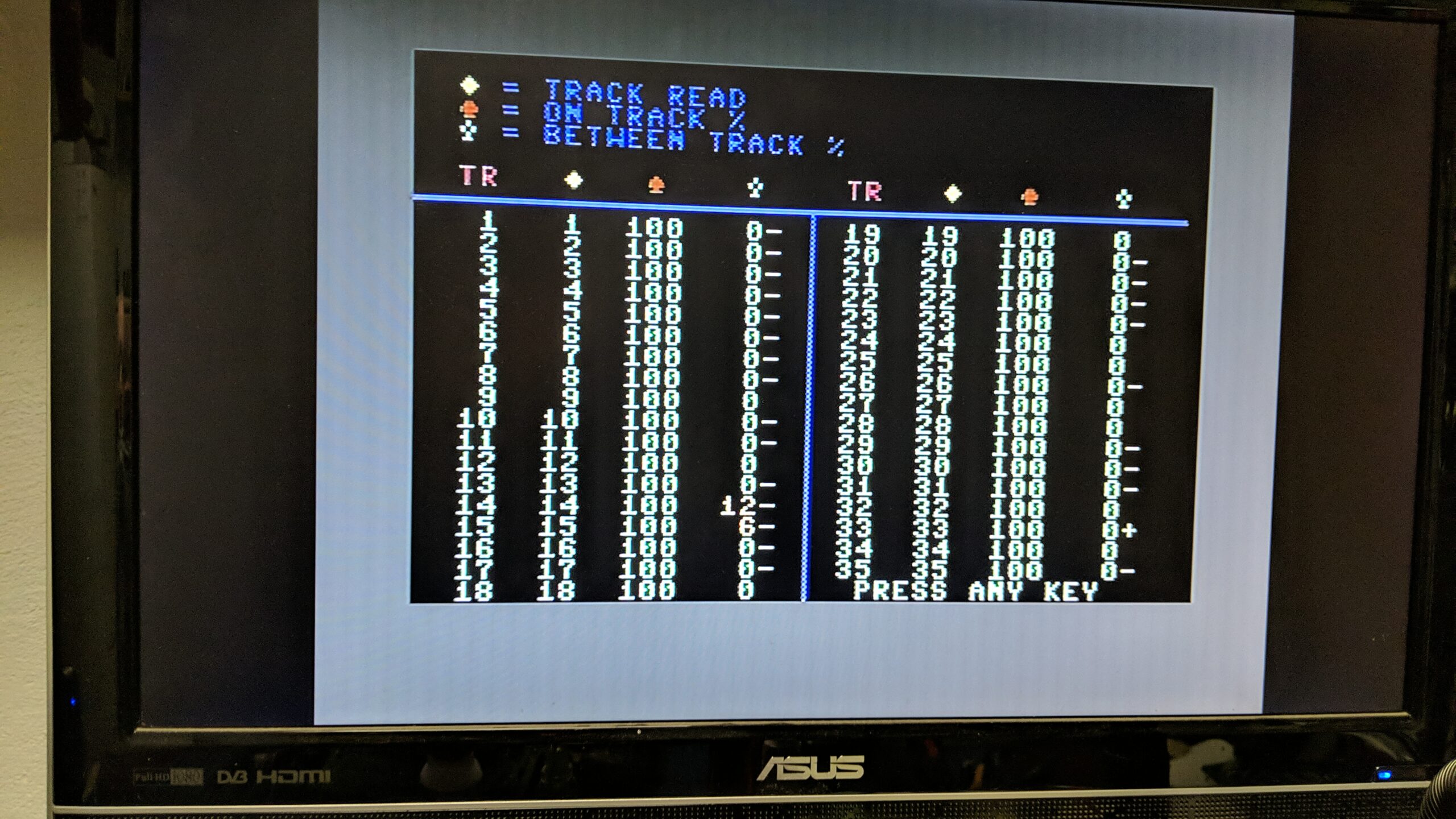
To align a drive, you need to loosen two screws on the drive motor and set it in such a way that it reads all tracks correctly. The best tool for this job that I know of is a part of the magnificent toolset CRT image that can be found on blog.worldofjani.com
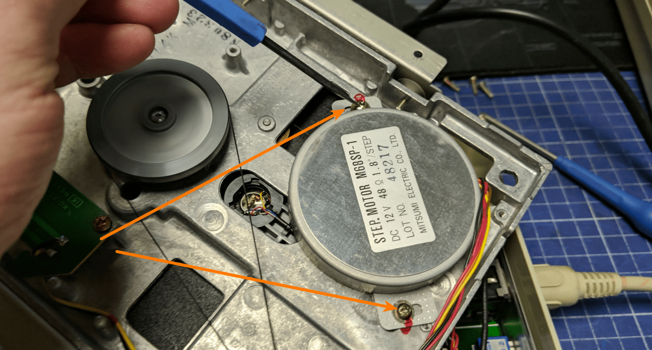
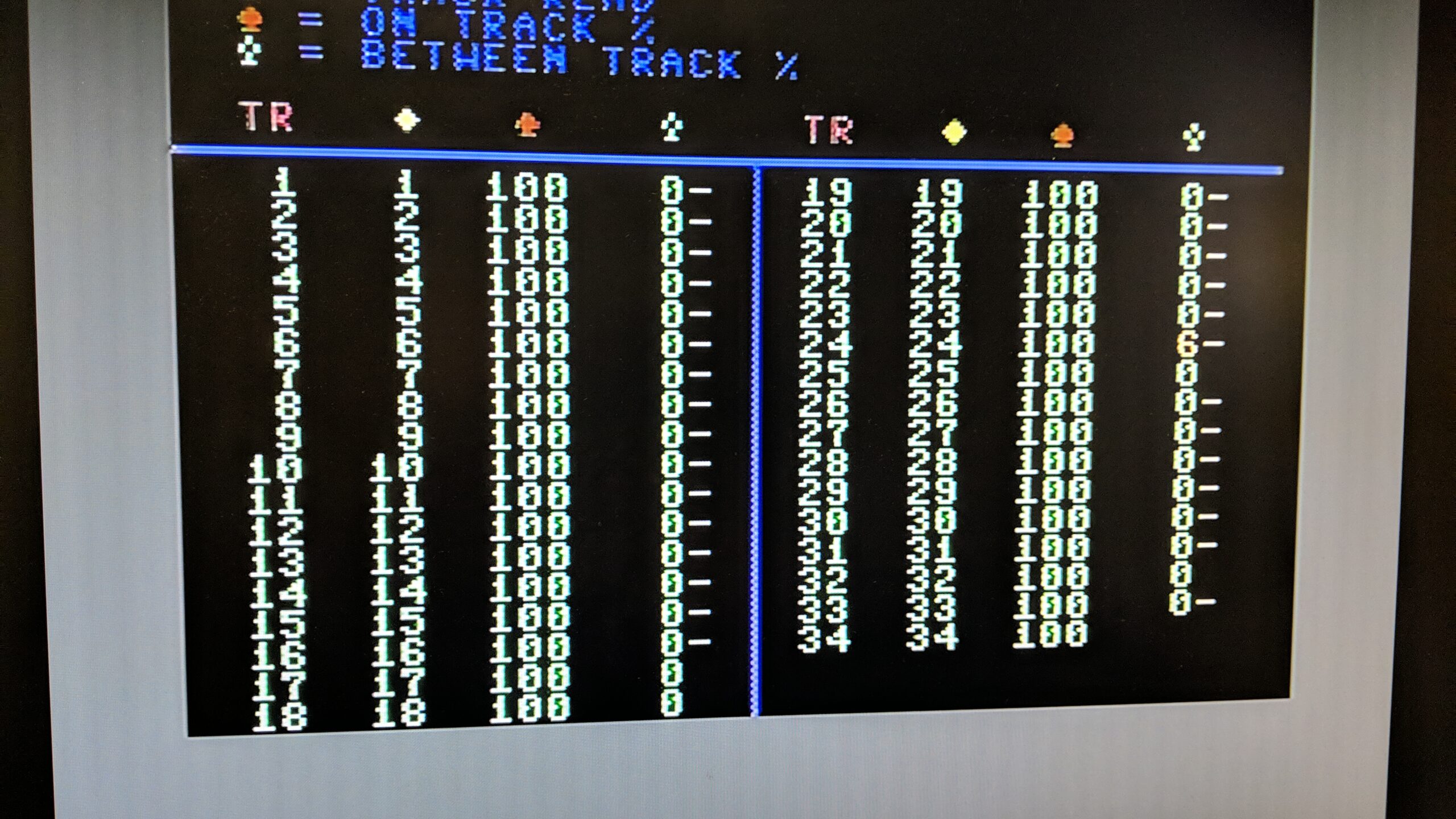
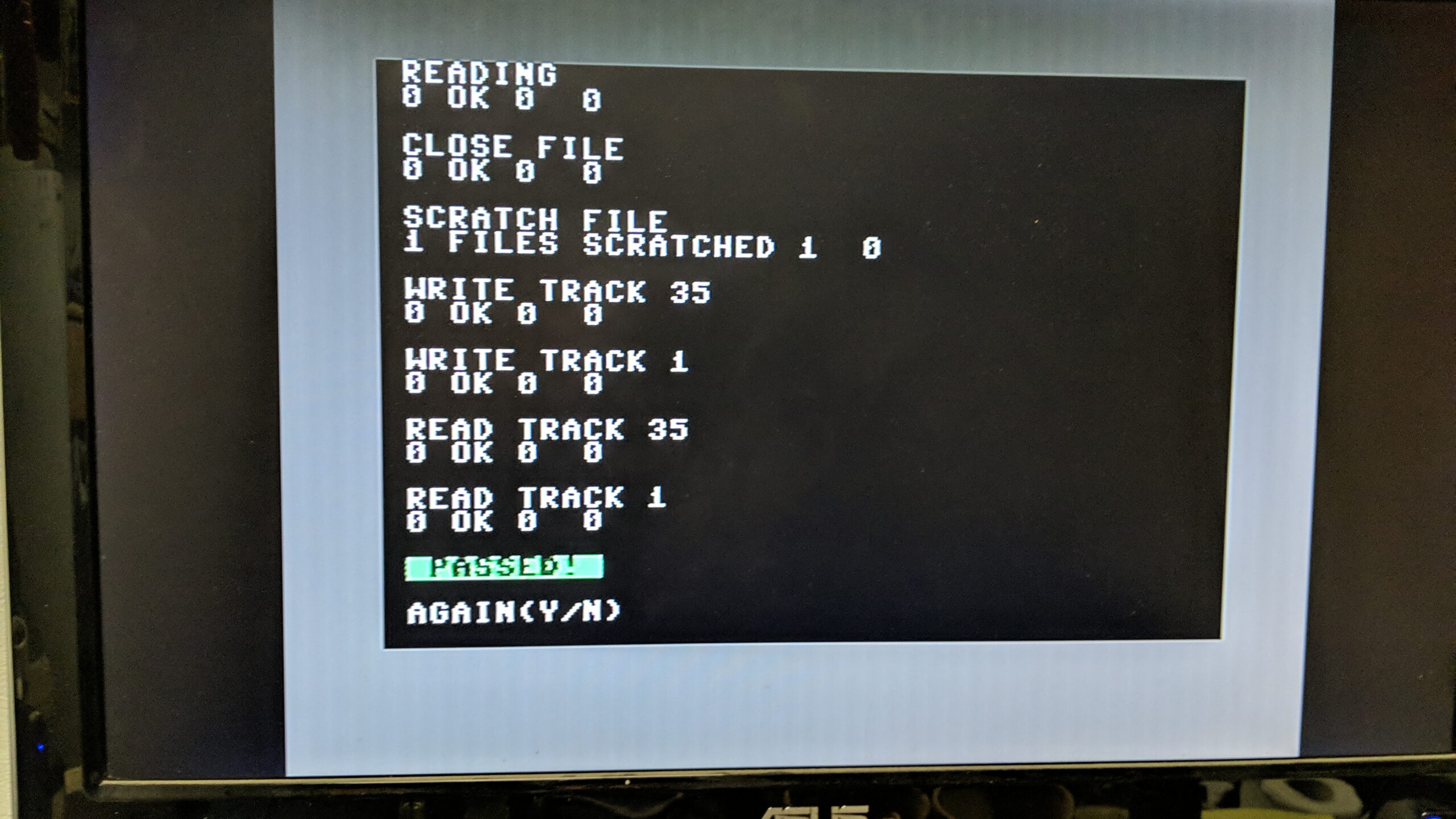
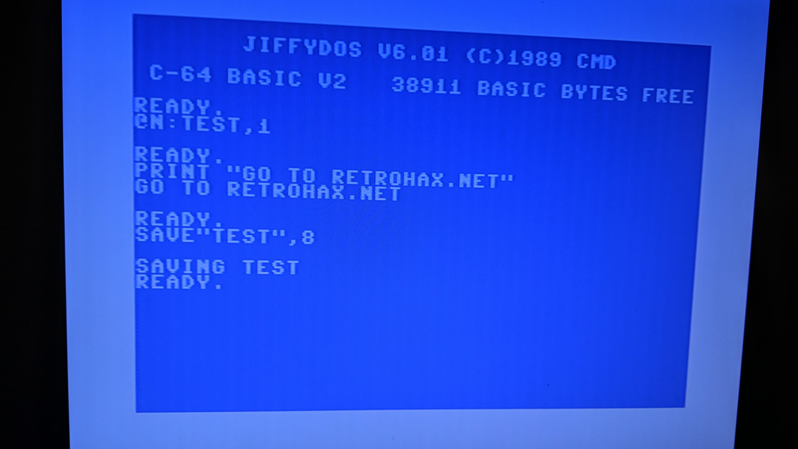
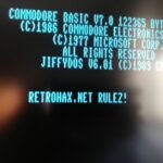
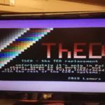
Once the screws are loose, I had to attempt to align them so the testing software shows the correct values.
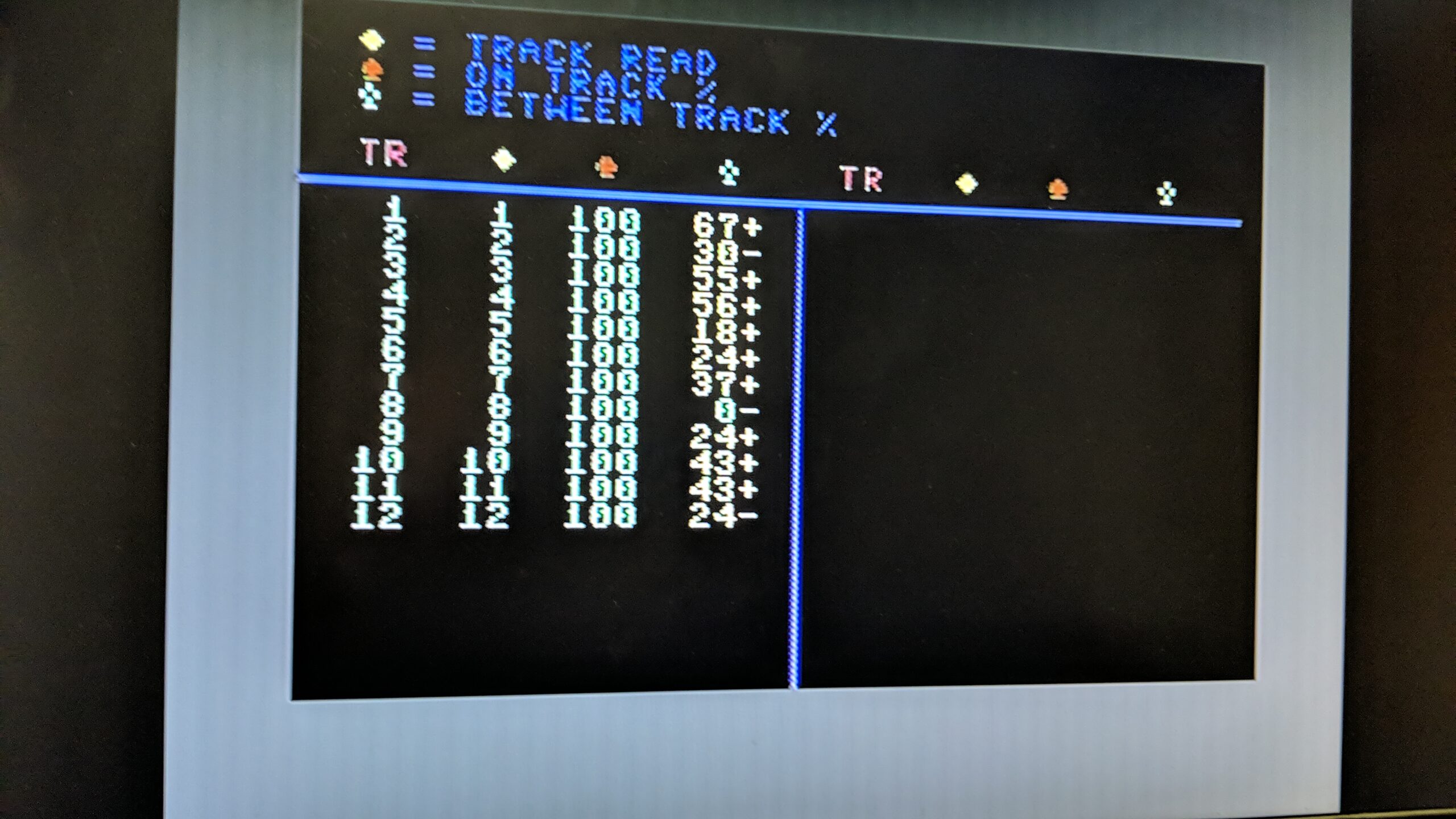
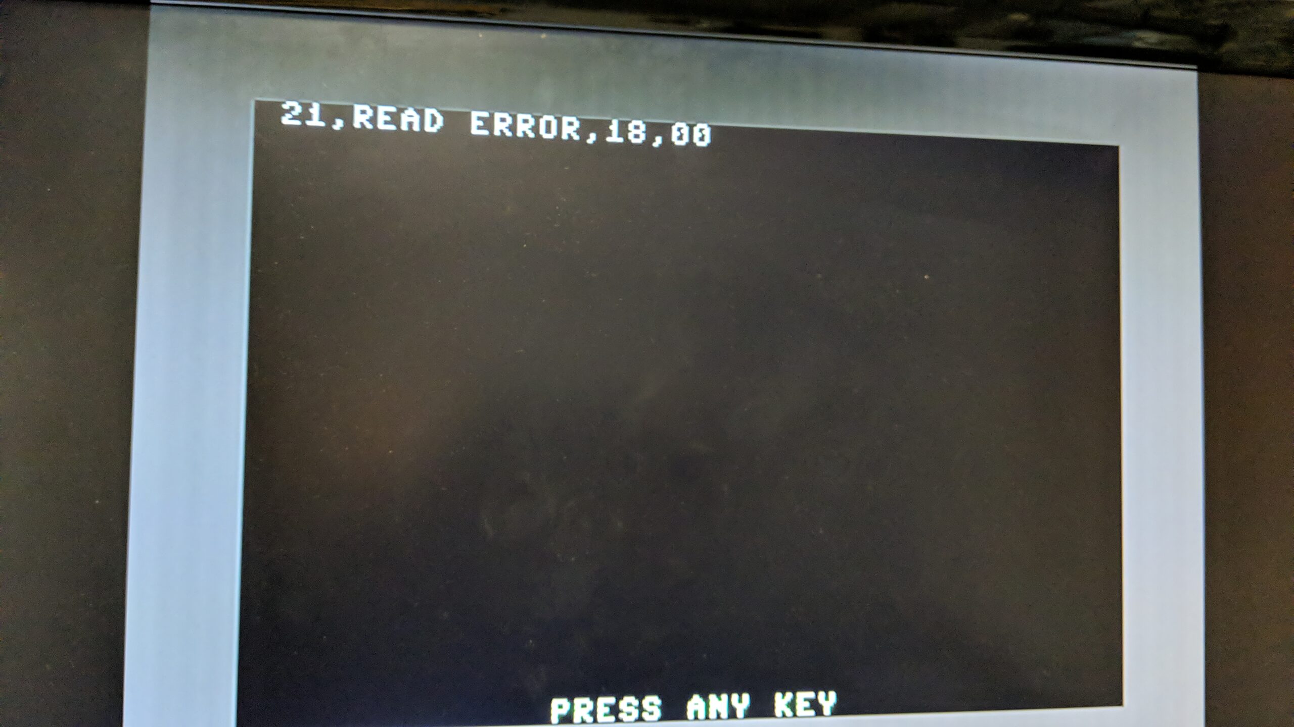
Below, are two screenshots of a drive that is totally out of alignment and in nearly perfect (track 24) alignment for comparison.
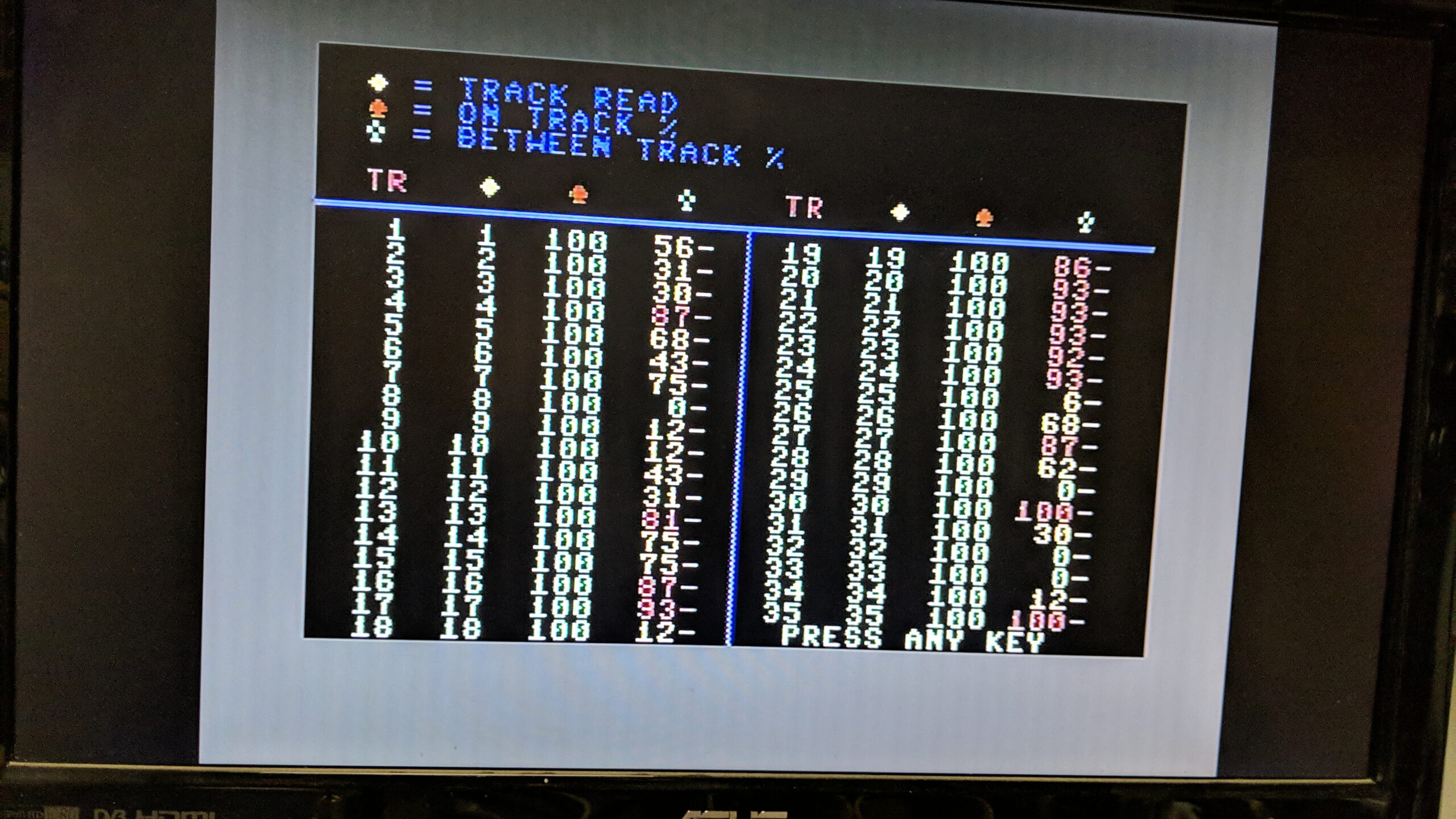
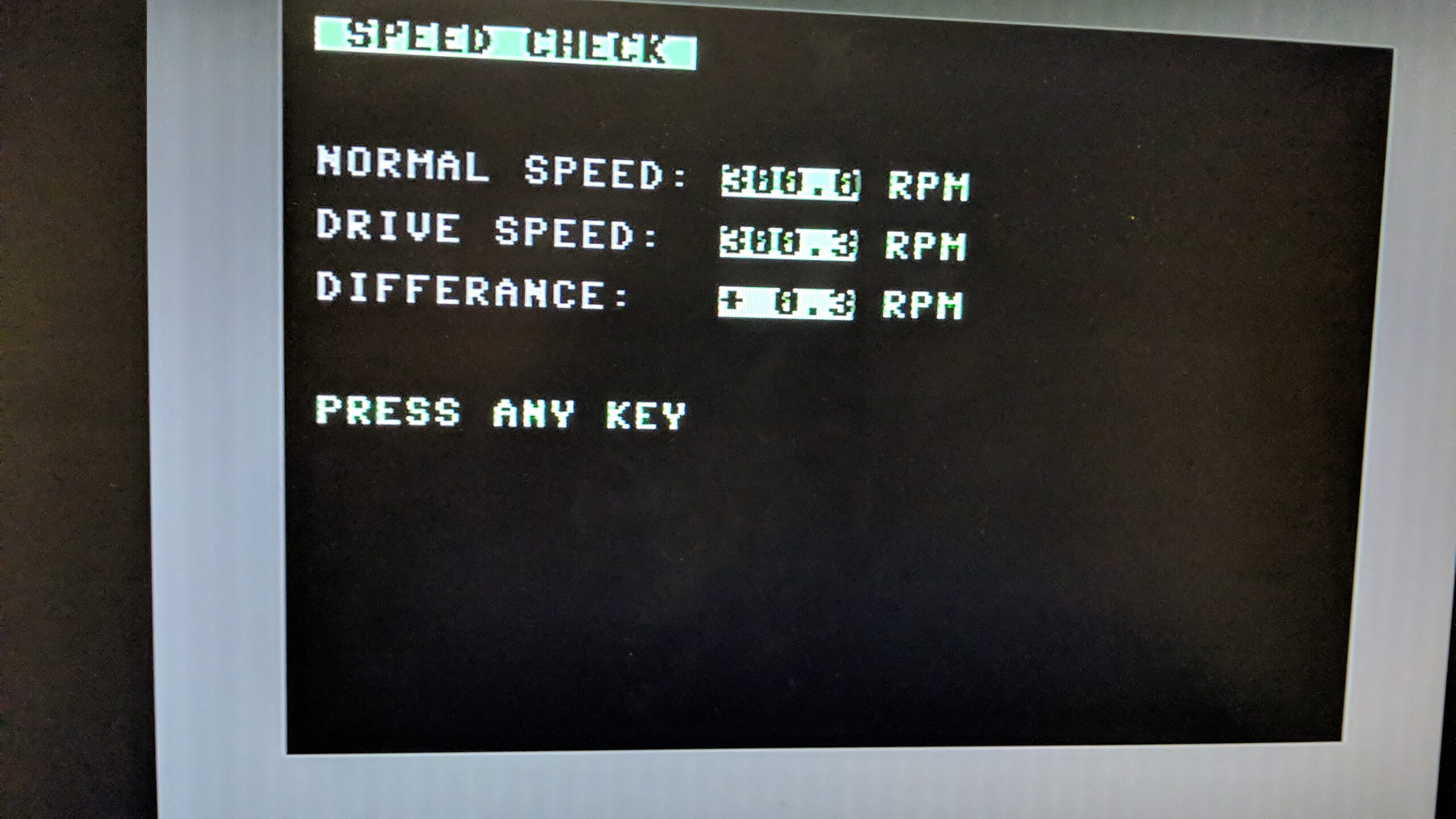
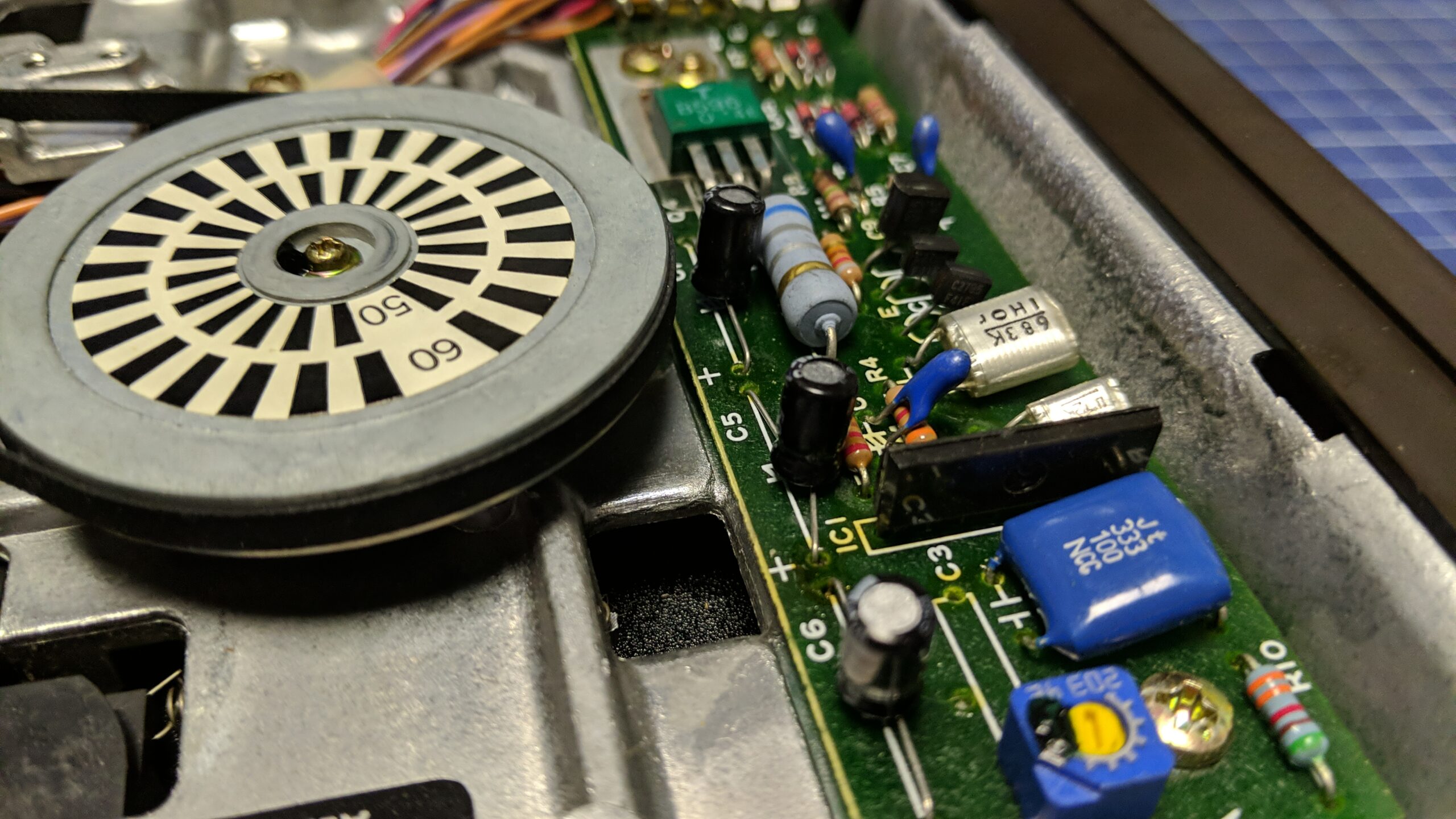
This all has to be done while the drive is spinning with the correct speed which for Commodore drives is 300 RPM. To measure it, I had to run another program from the CRT image and tune the speed by turning a pot on a drive’s PCB.
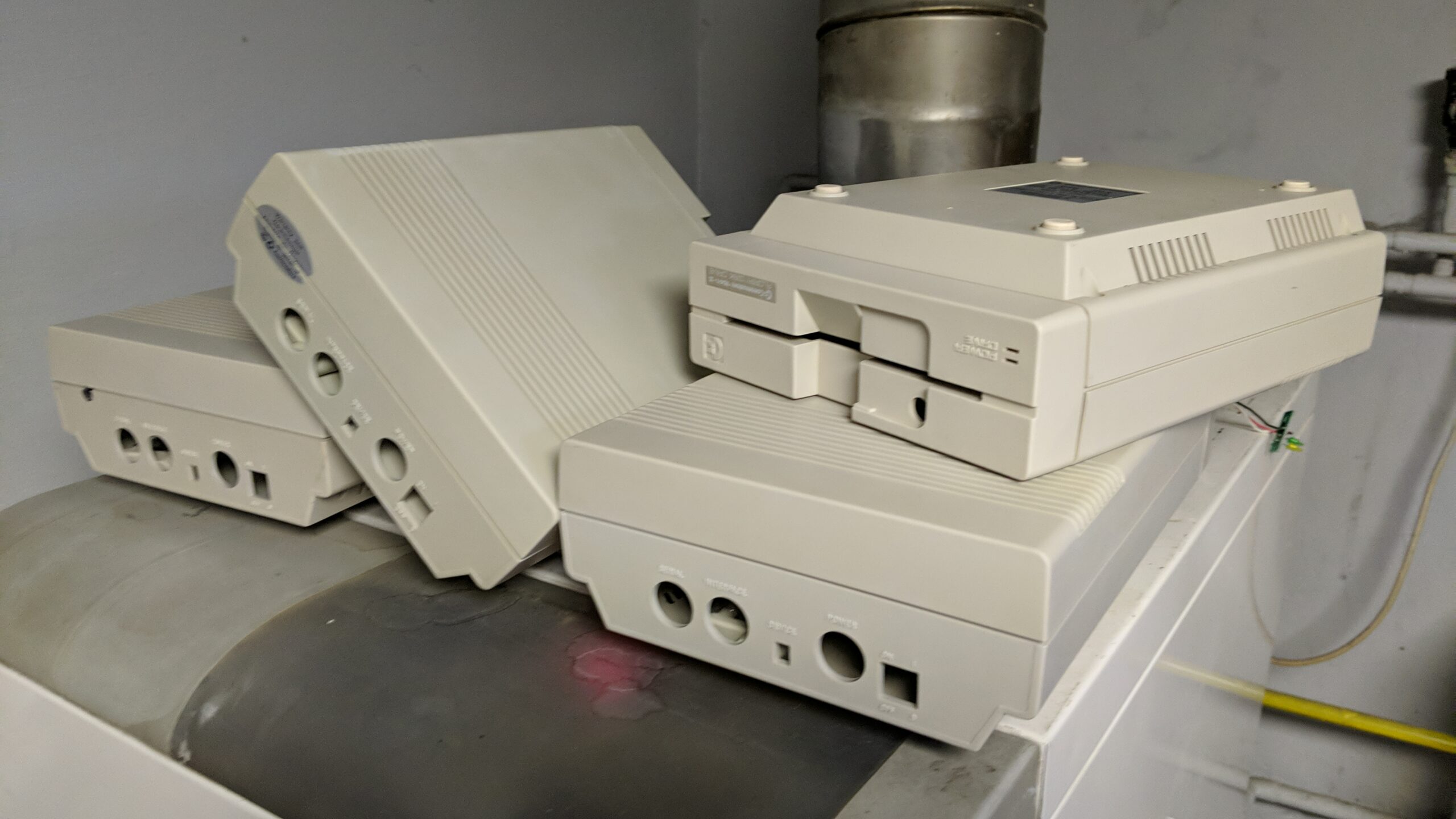
After all above, I assembled all four drives and was ready for the final test which went smoothly this time 😉
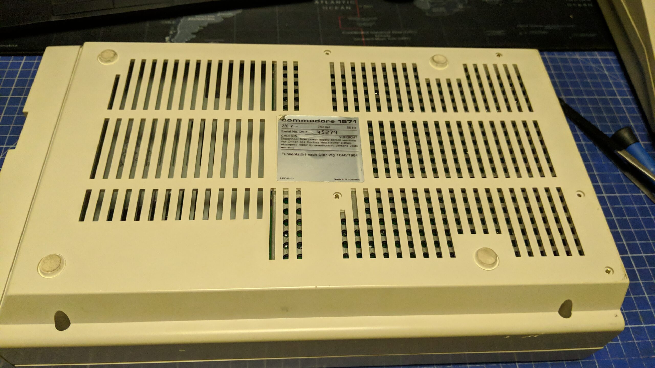
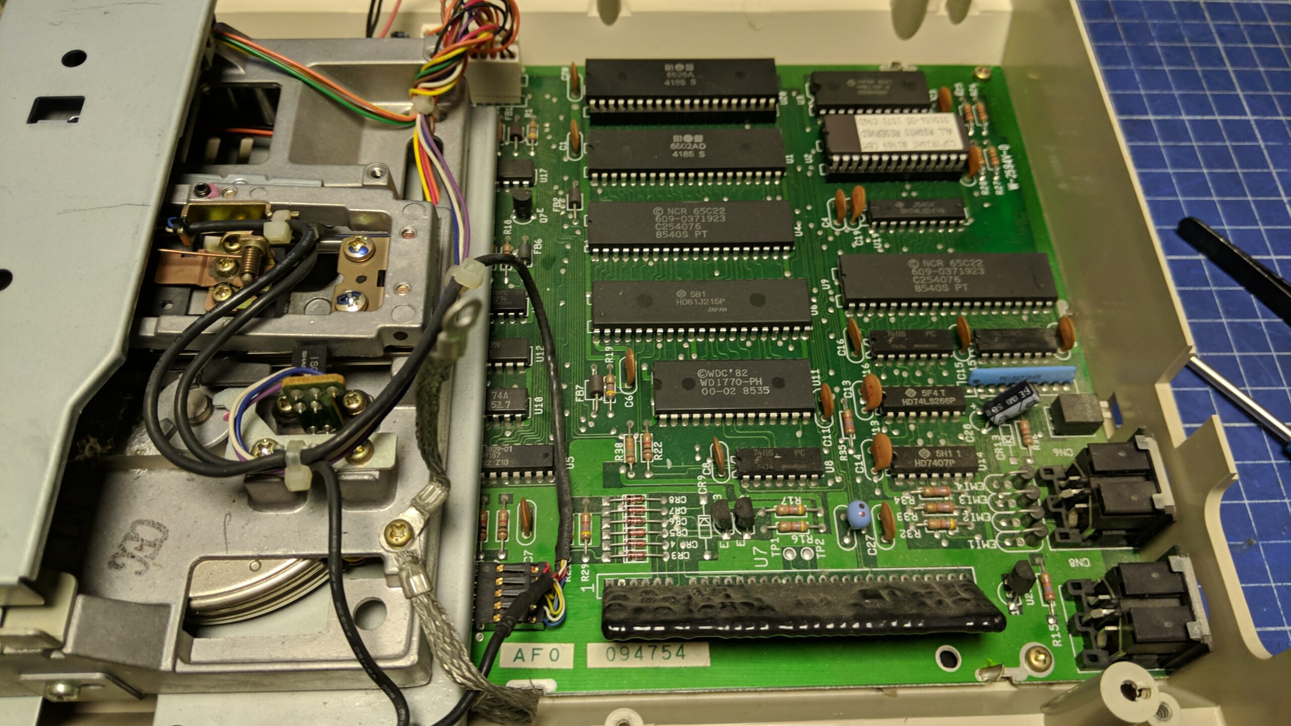
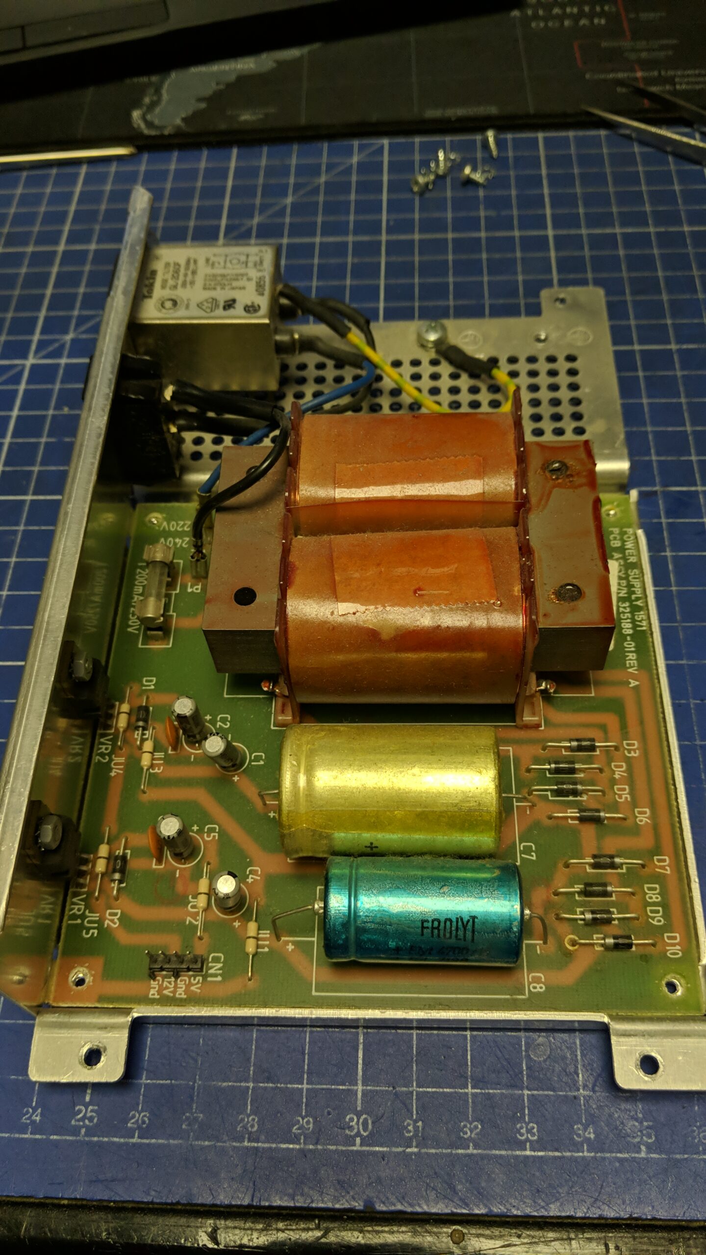
2x 1571
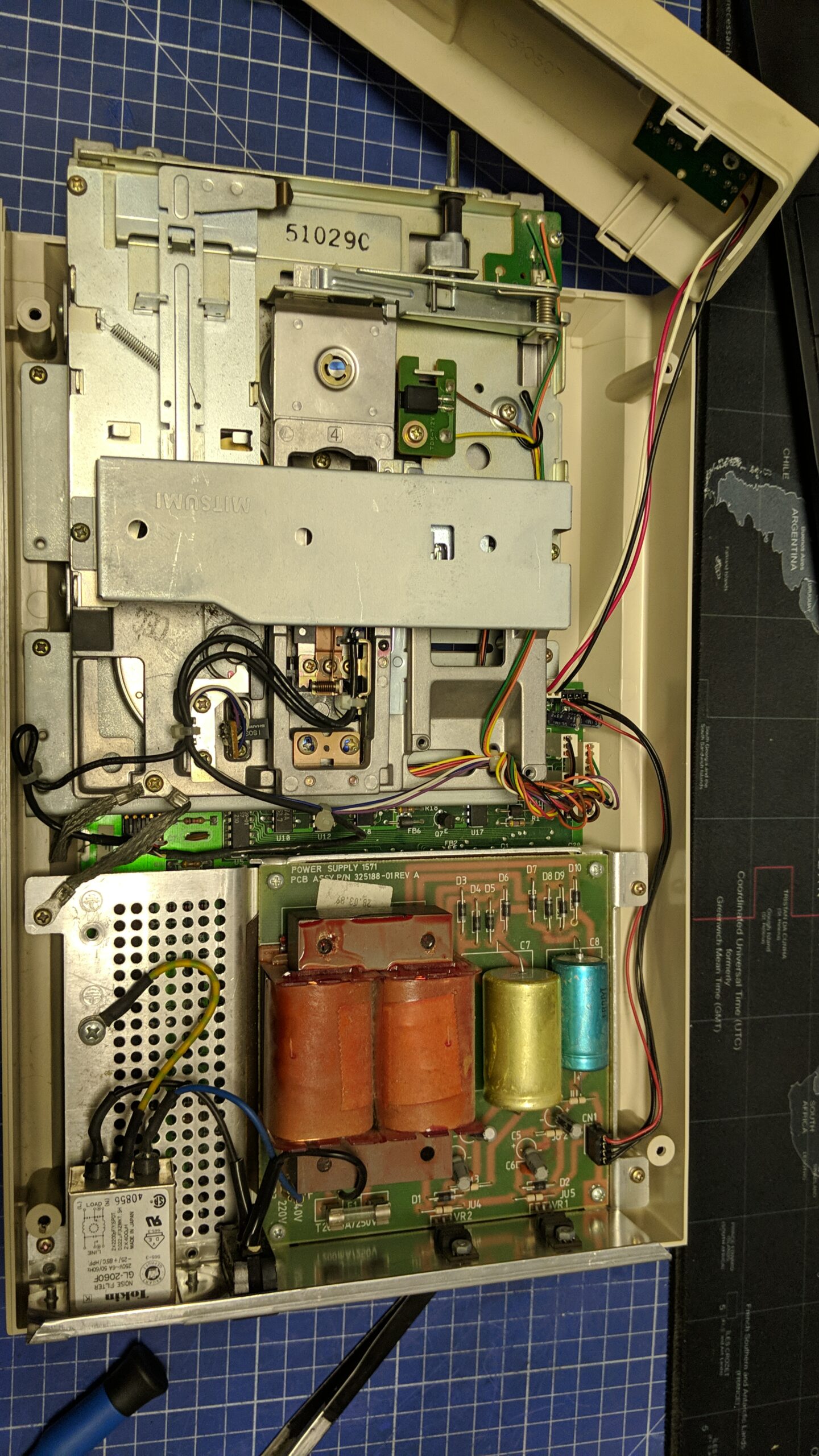
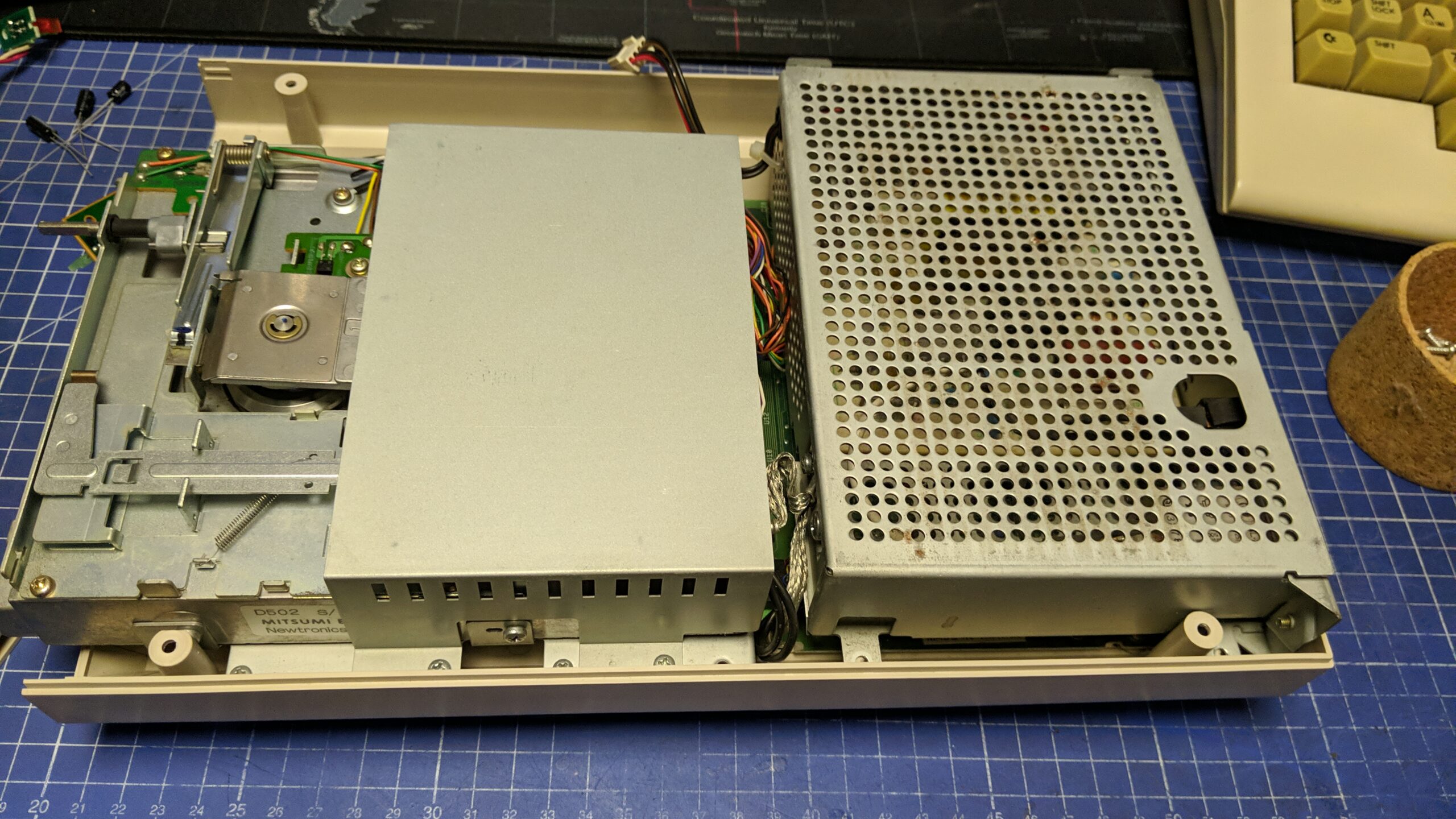
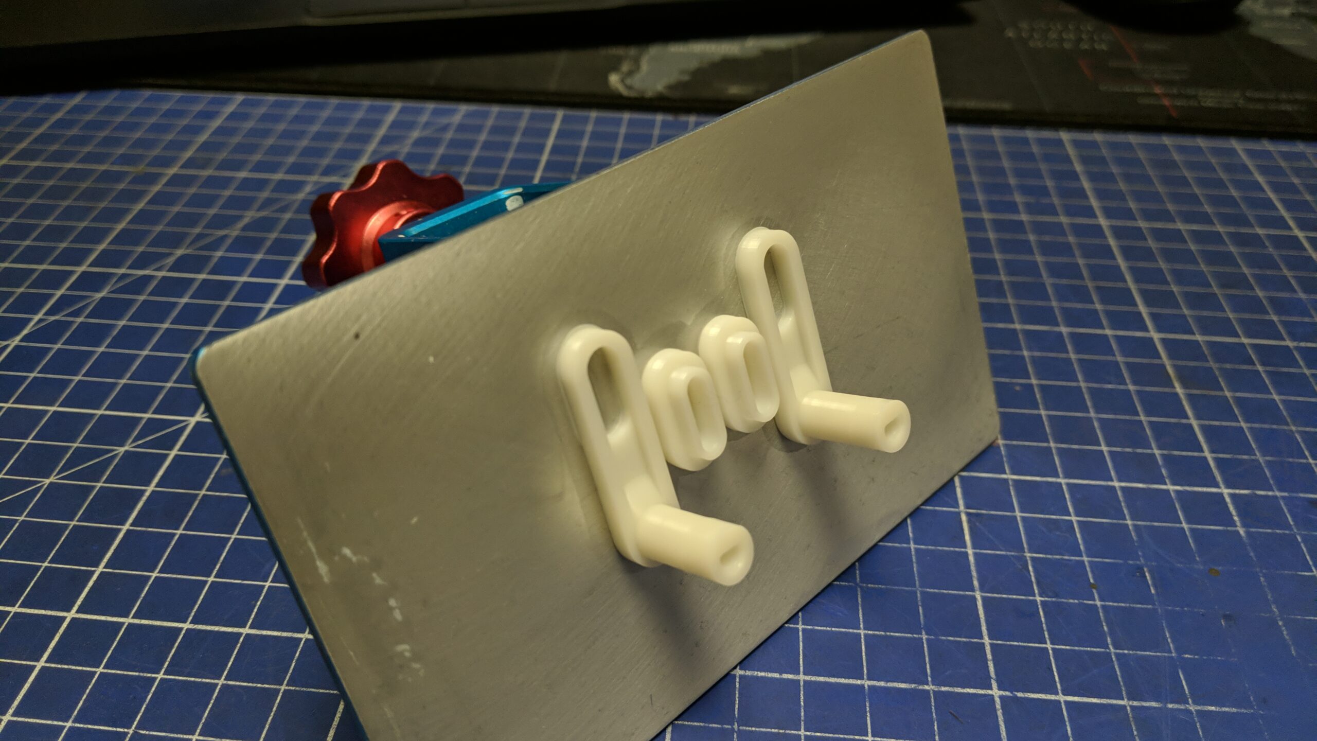
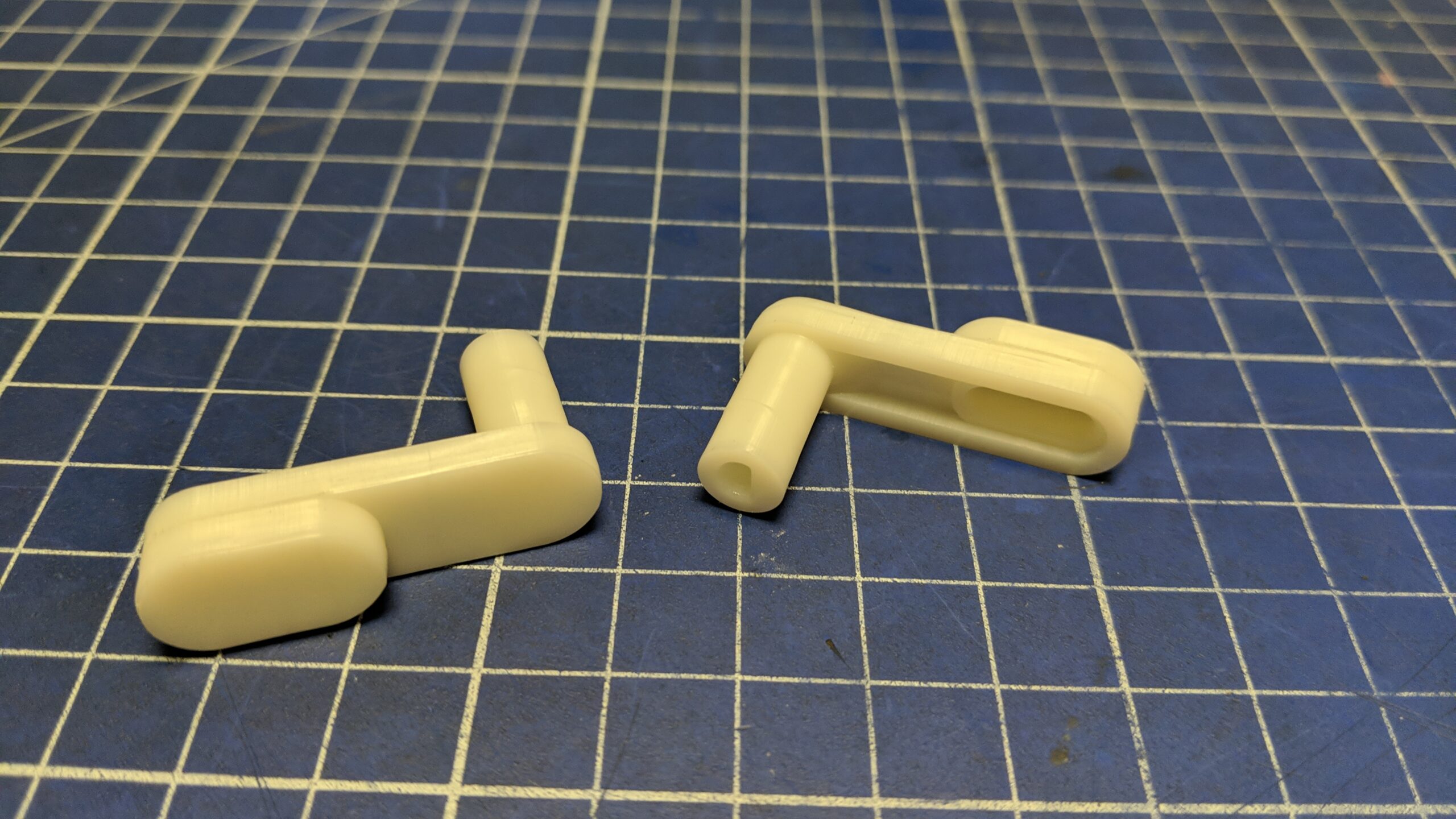
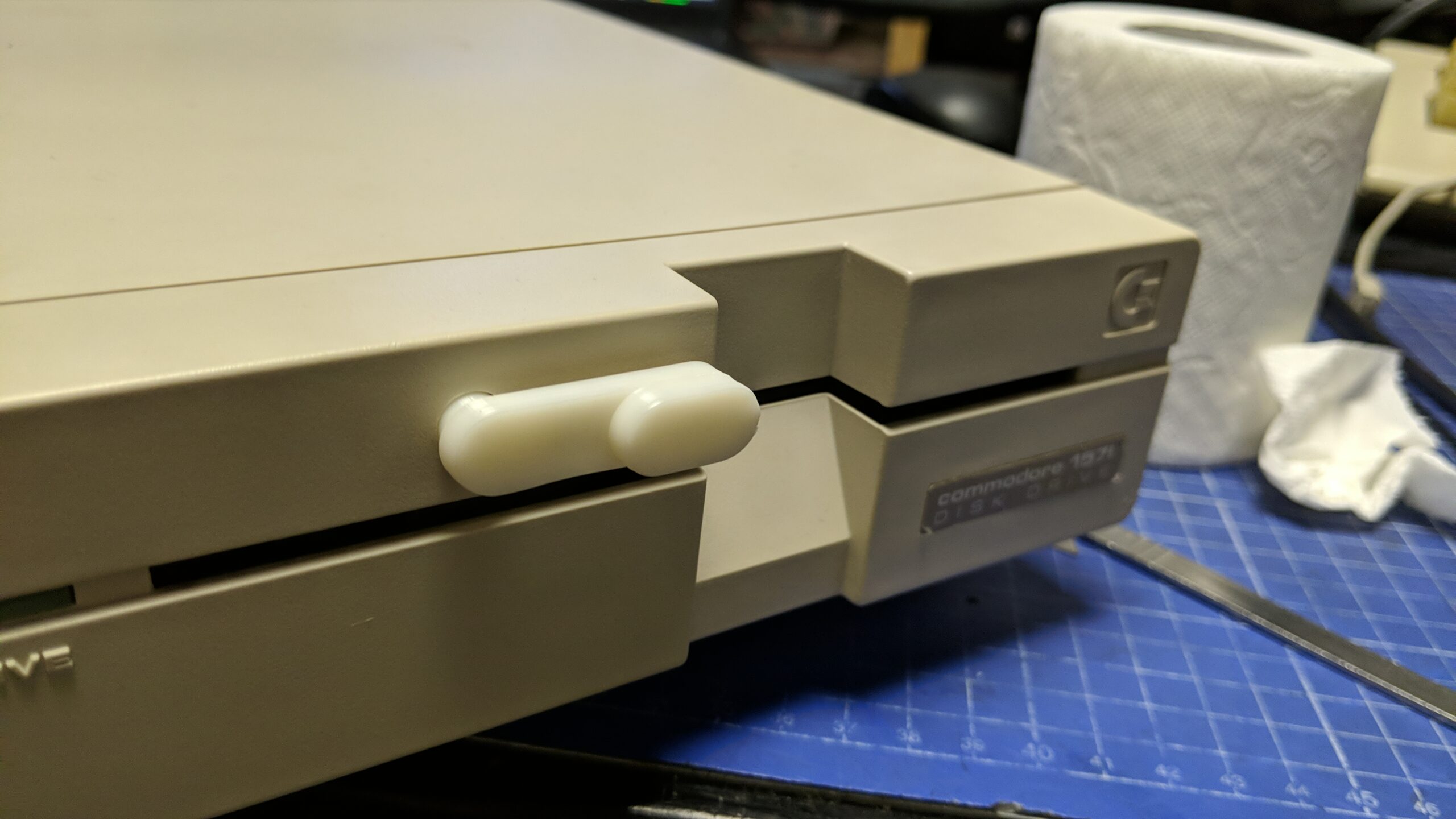
1571s are in my opinion the best drives to work on. It is pretty much the same story as with 1541-II but that went even smoother. Disassembly, cleaning, retr0brighting, re-capping, assembly, and testing. The only problem to sort out was a missing lever but I easily 3D printed it out of white UV resin.
Below, are some pics of the work.
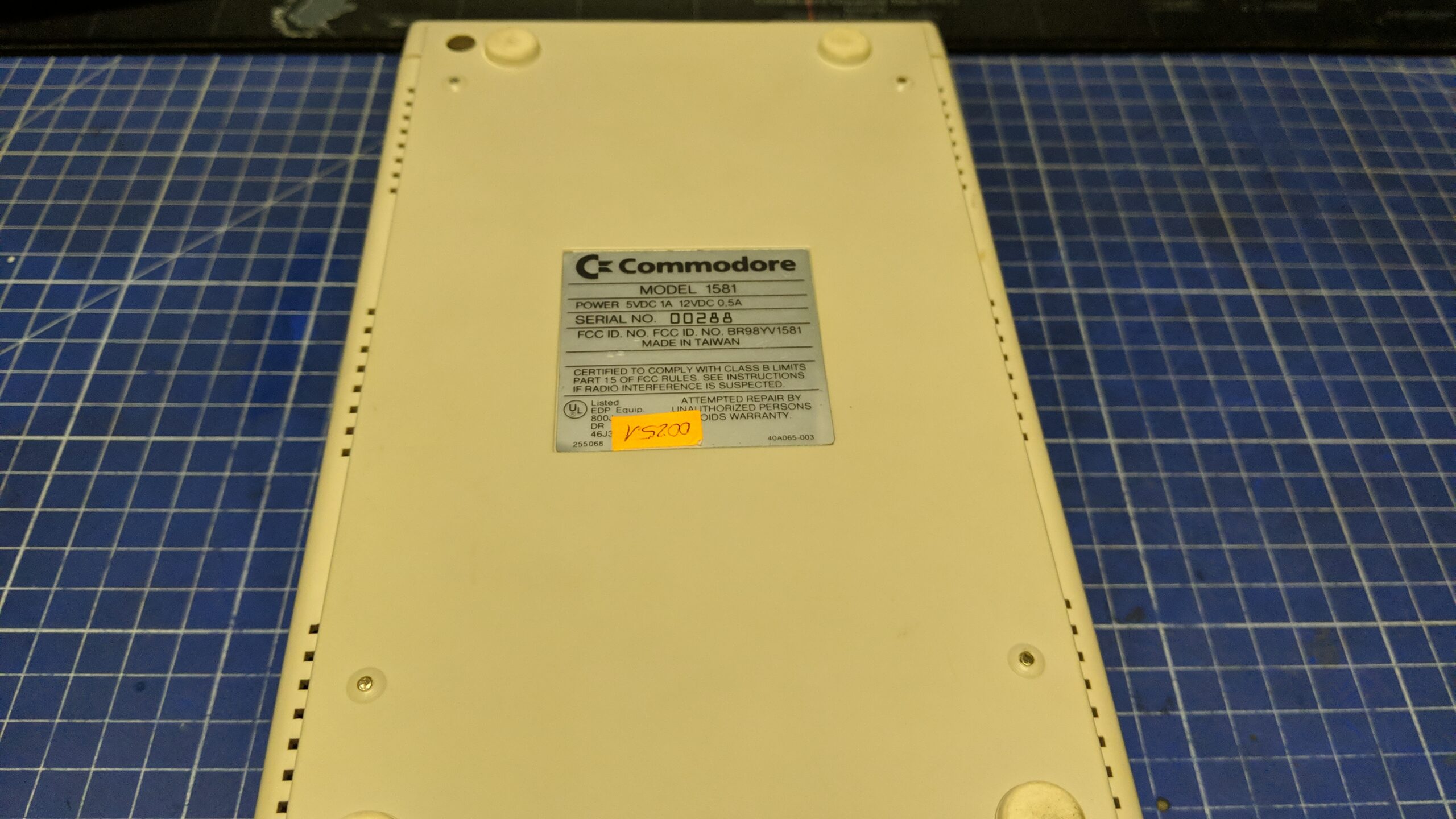
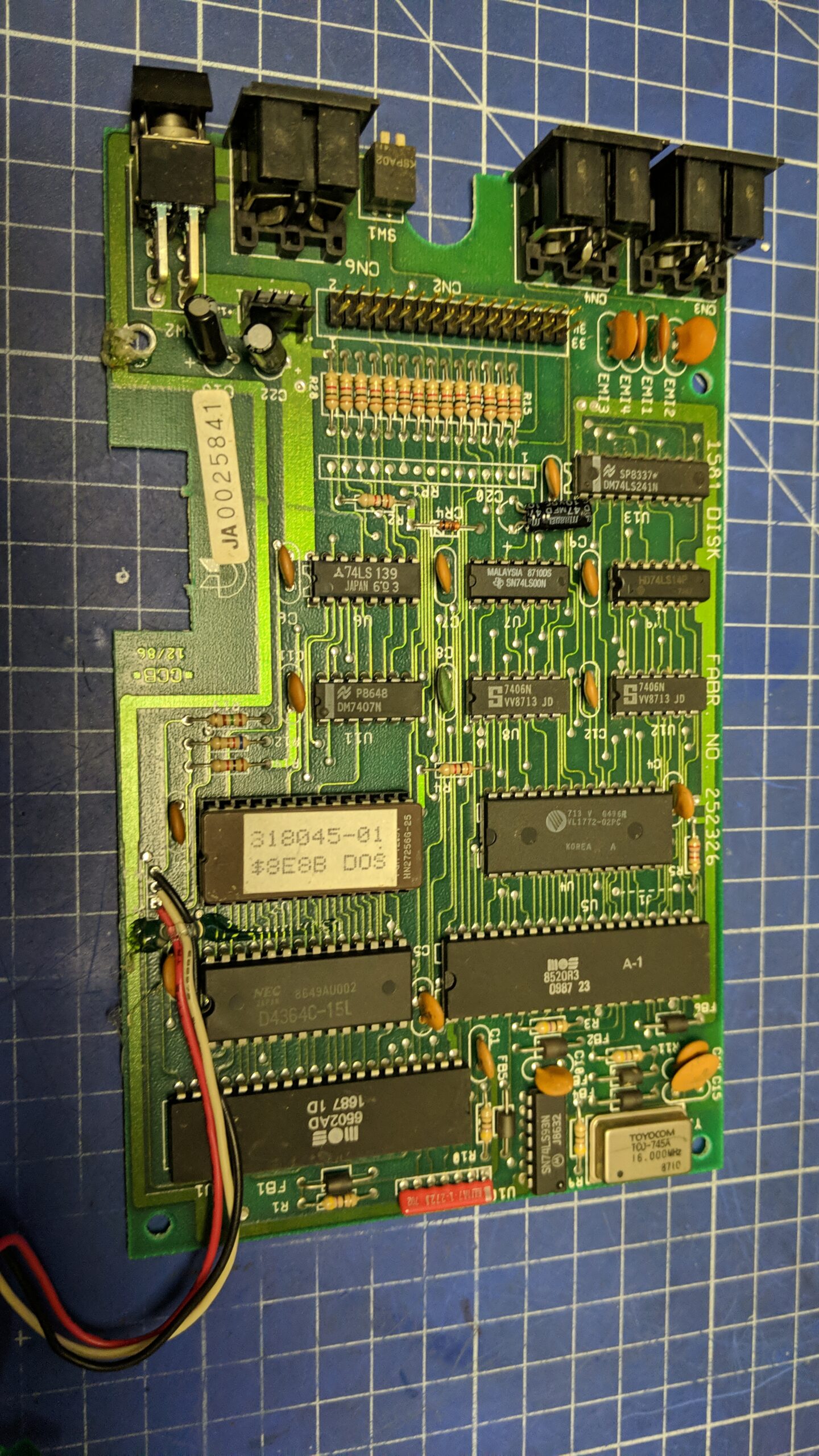
1581
I also had one Commodore 1581 to work on. It was in very good condition and it only required minor cleaning, re-capping, and lubricating.
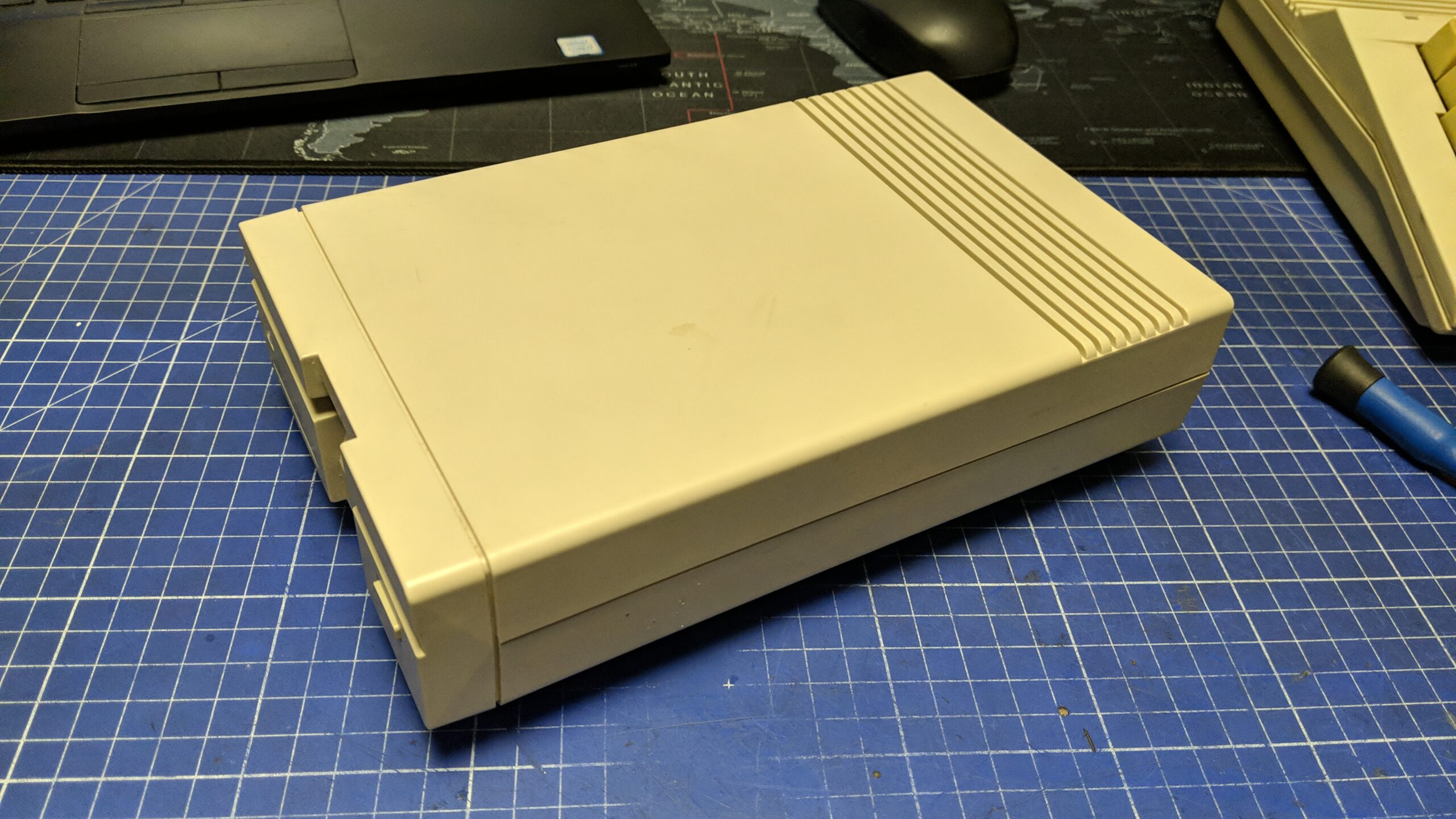
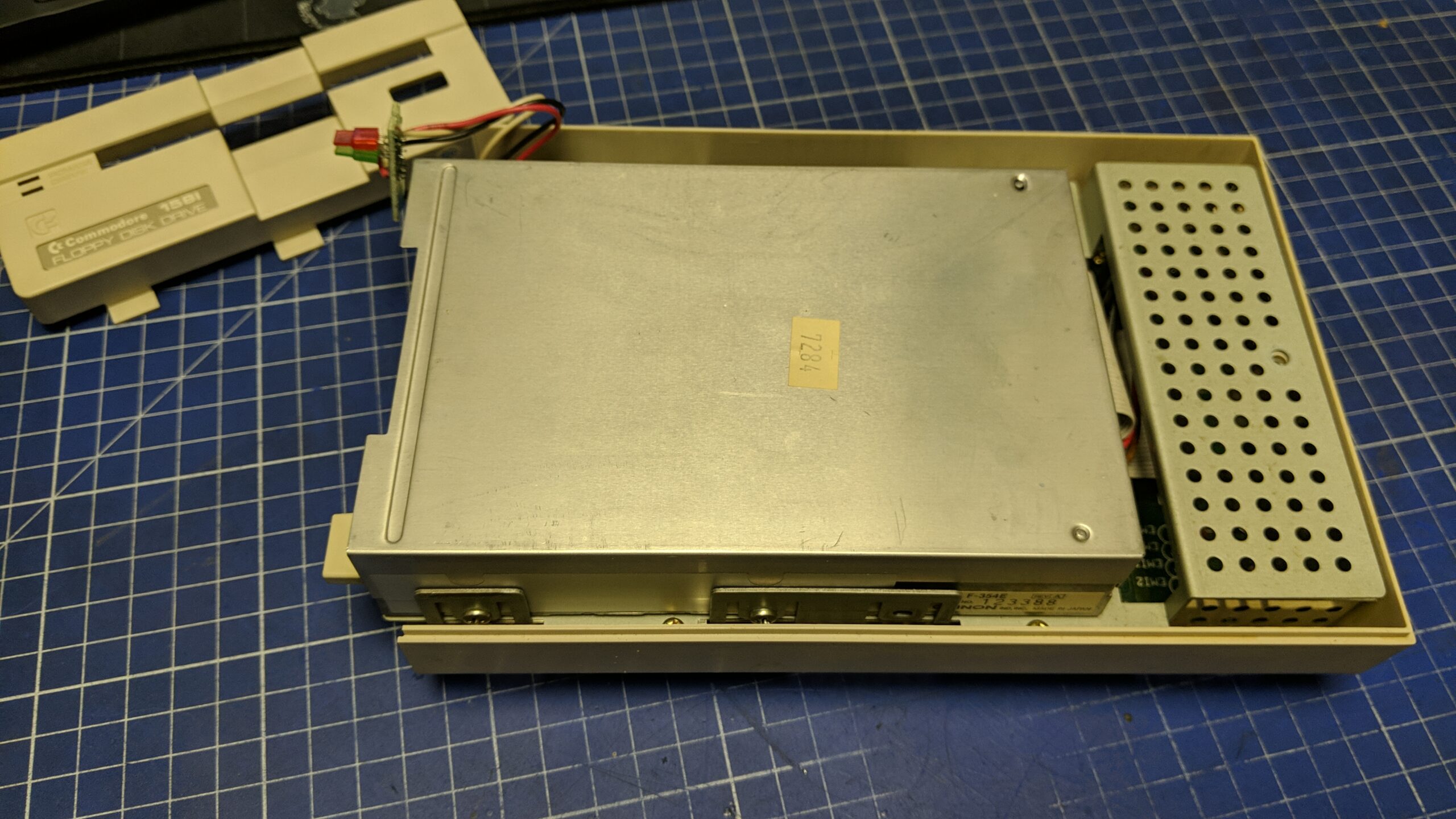
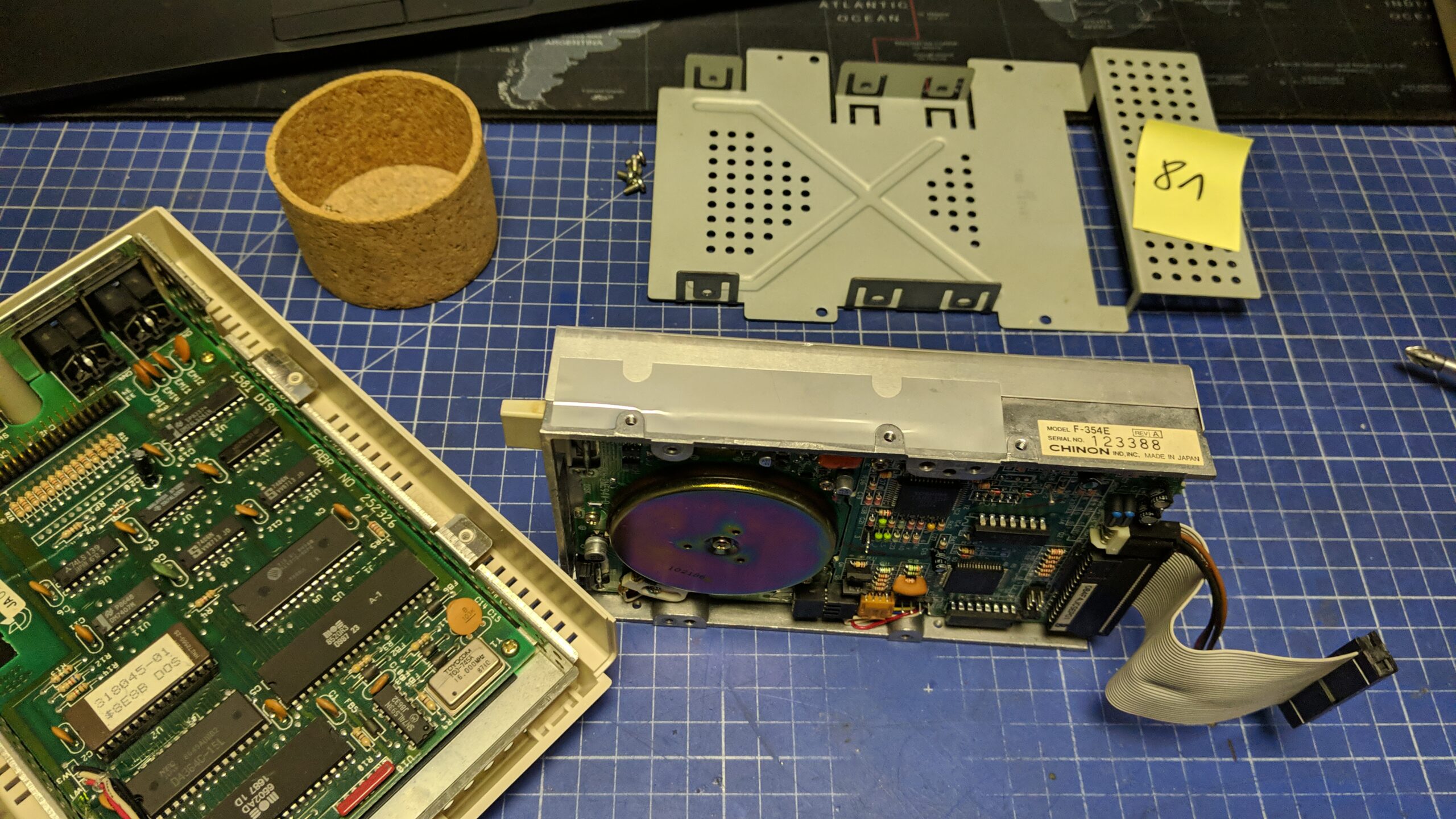
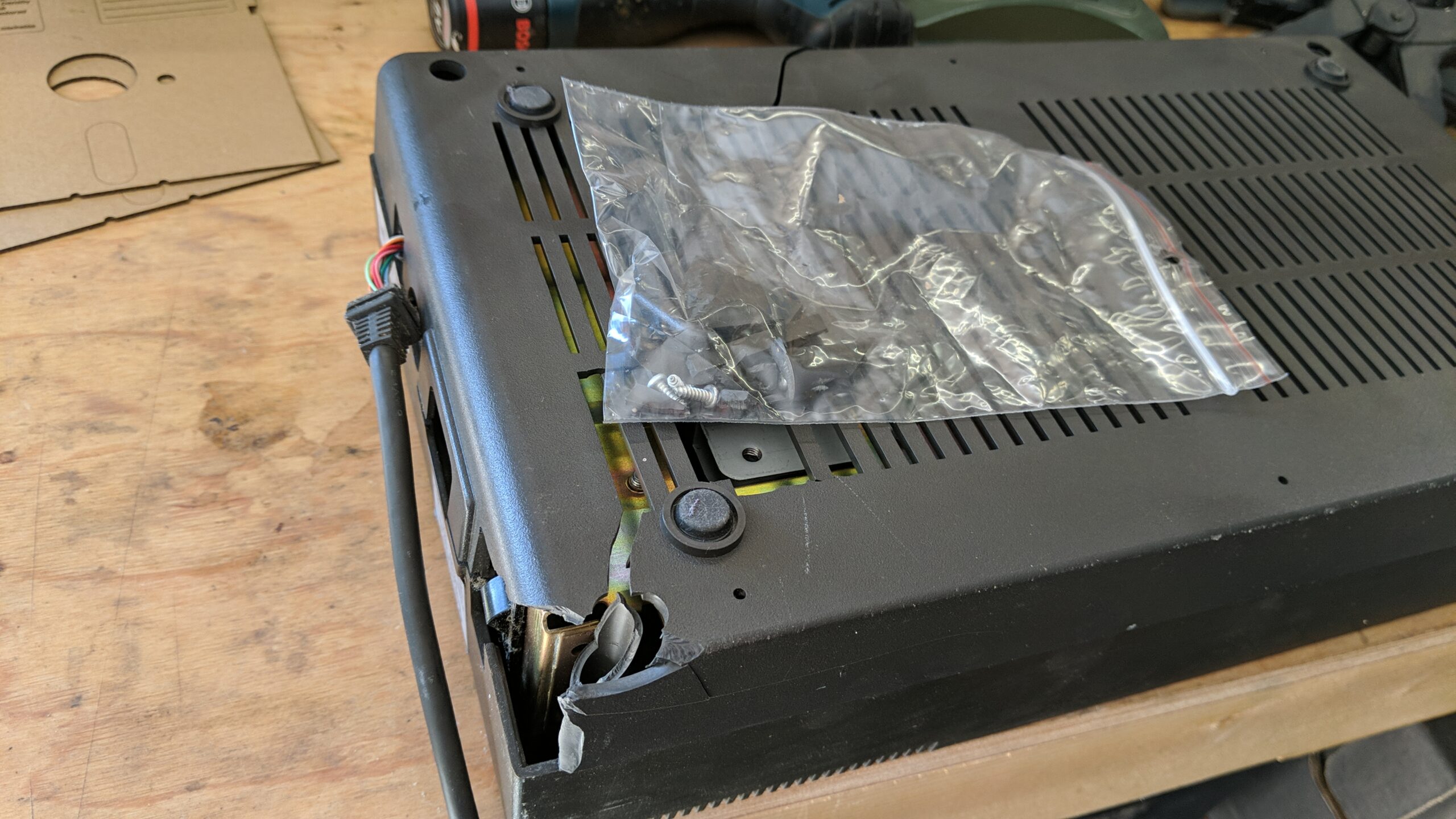
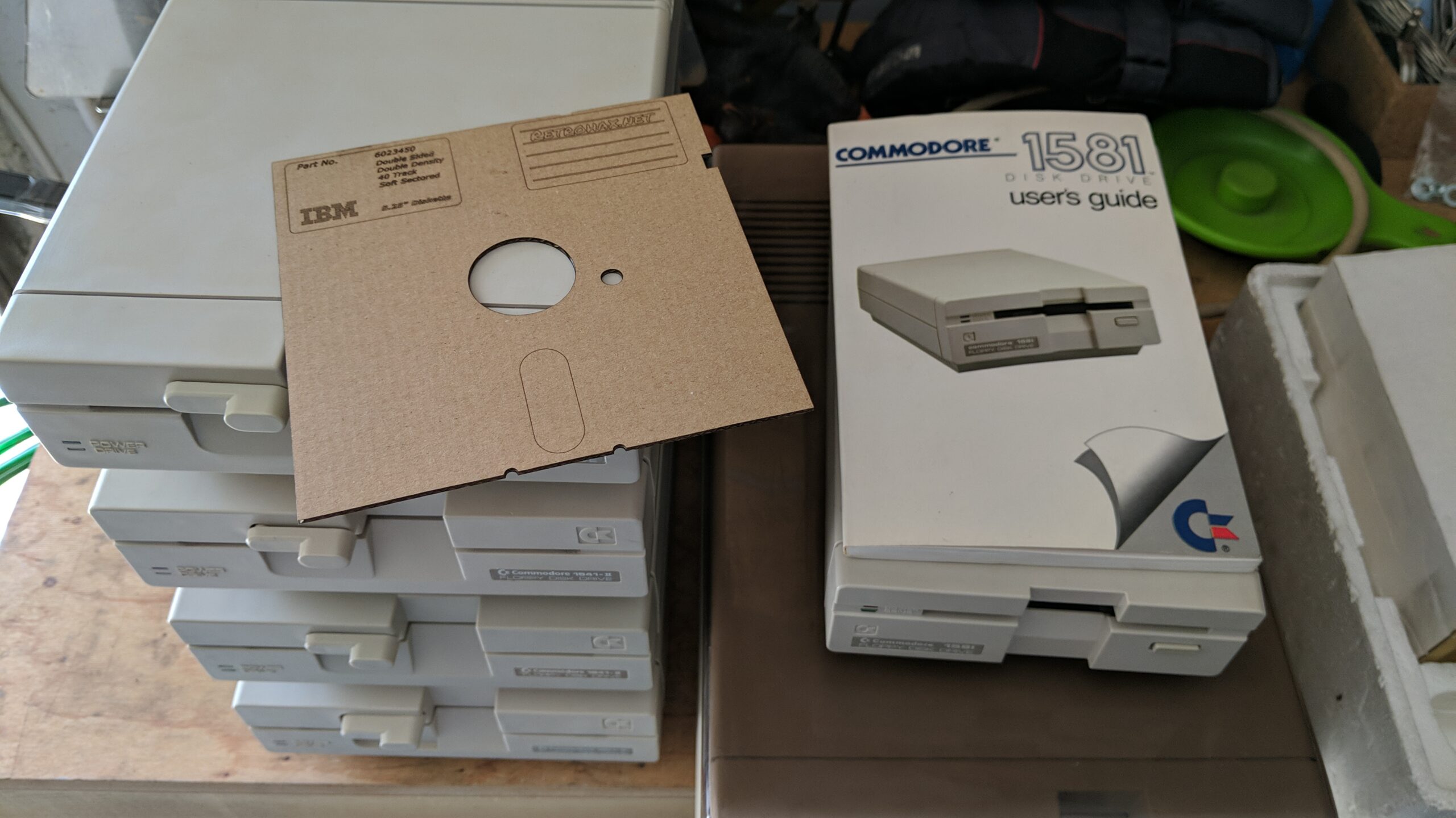
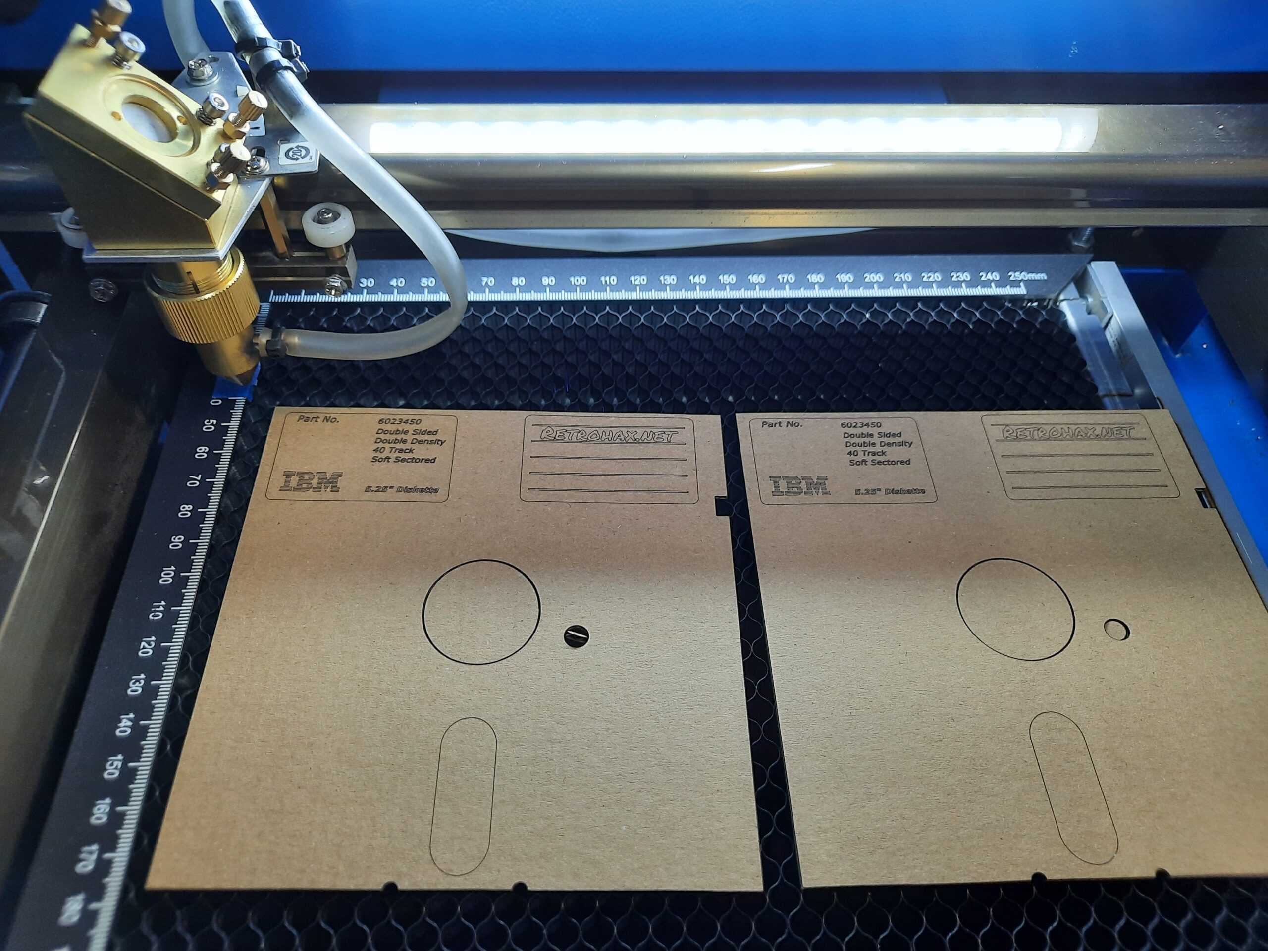
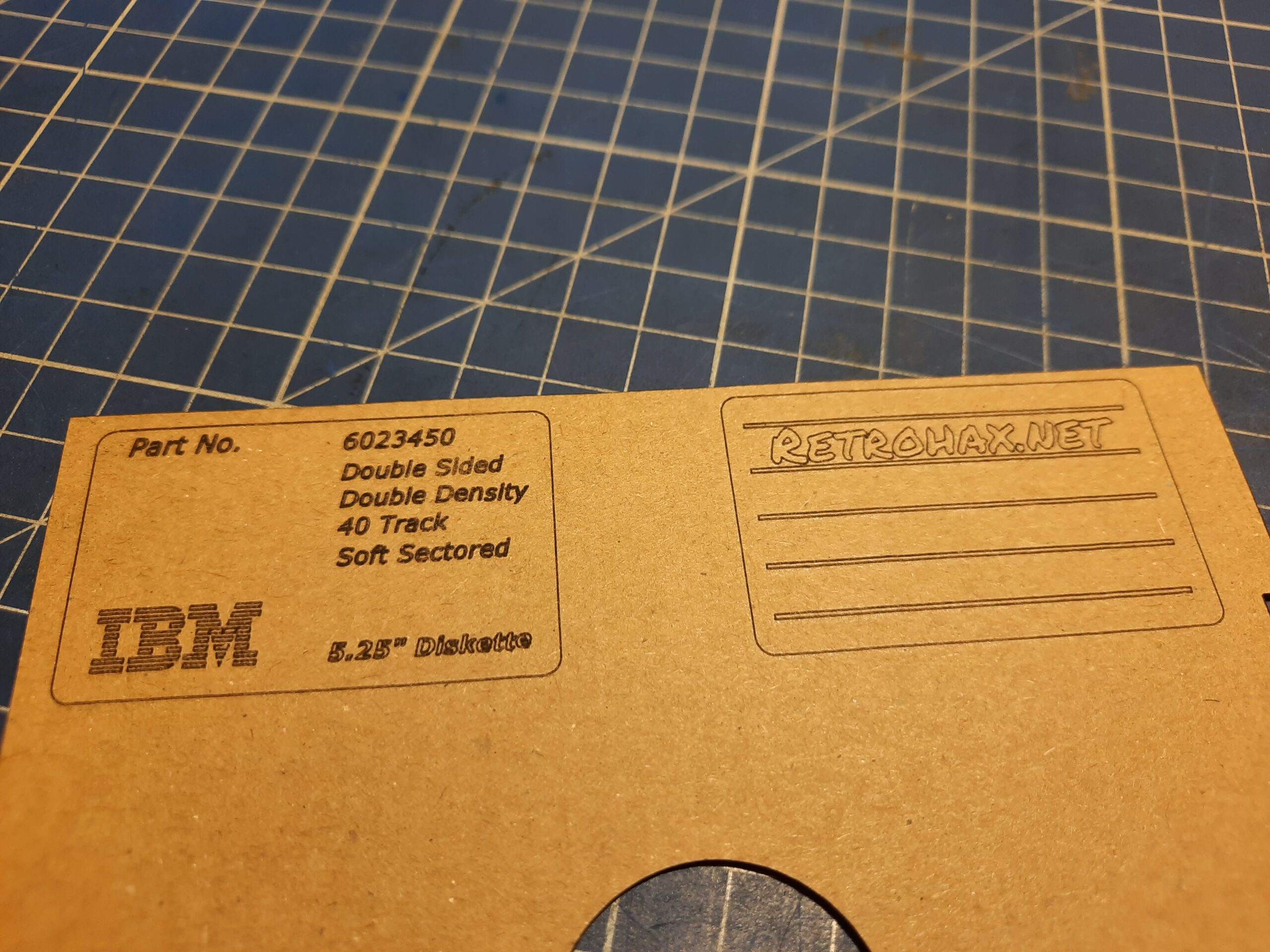
Short summary of work done so far, in the form of pics. I’ve laser cut some cardboard inserts to prevent magnetic head bumping during transport.
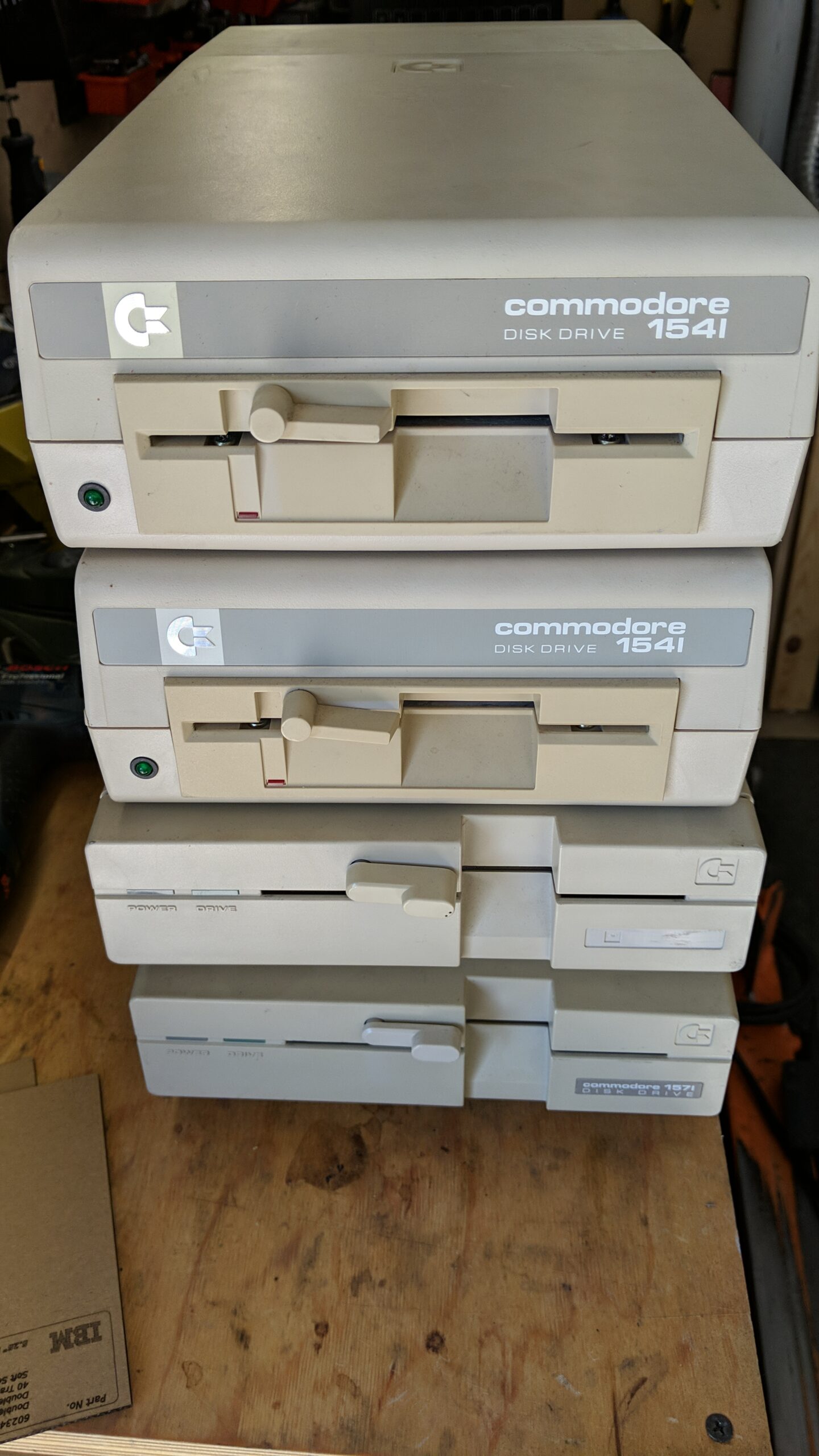
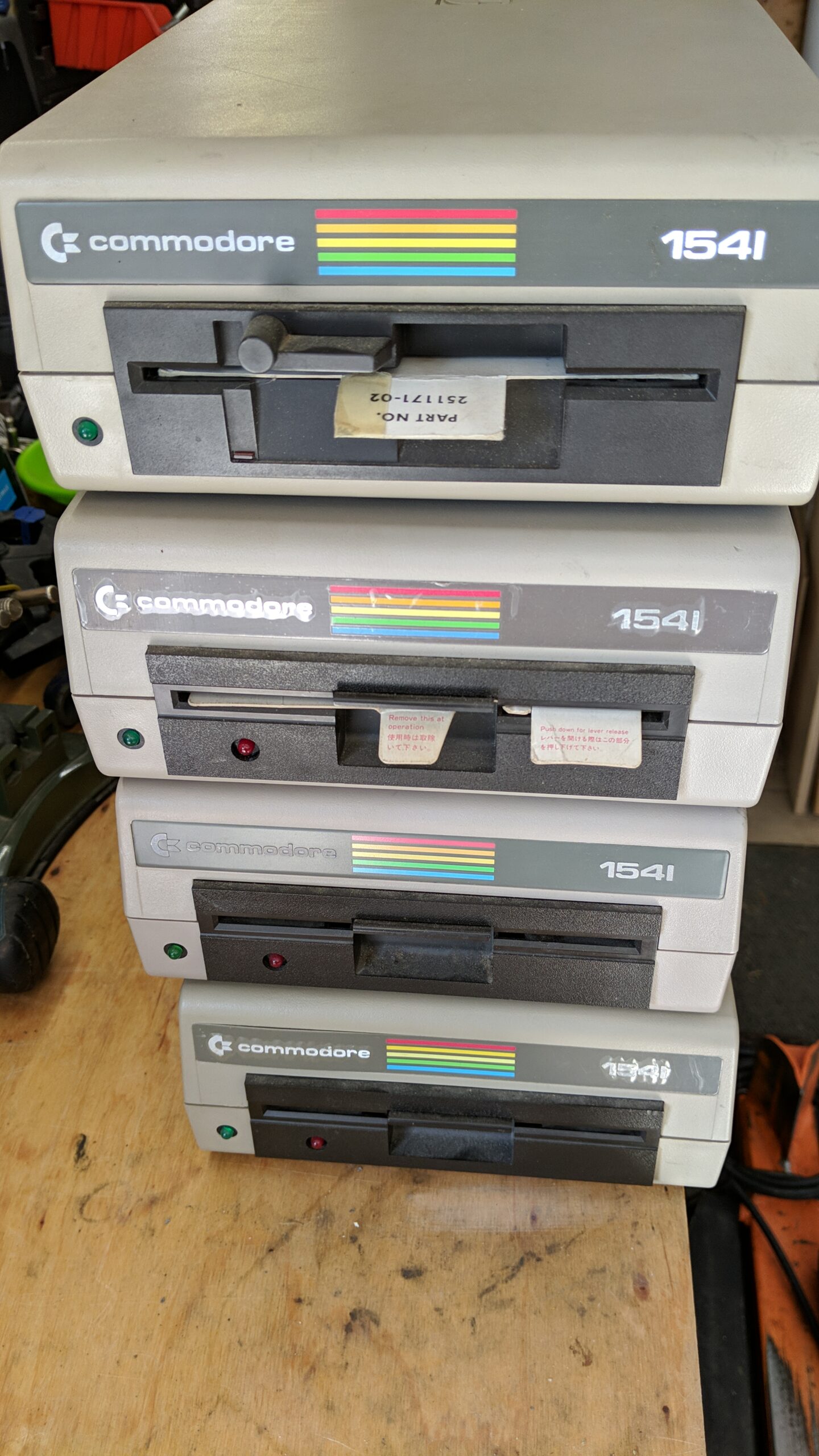
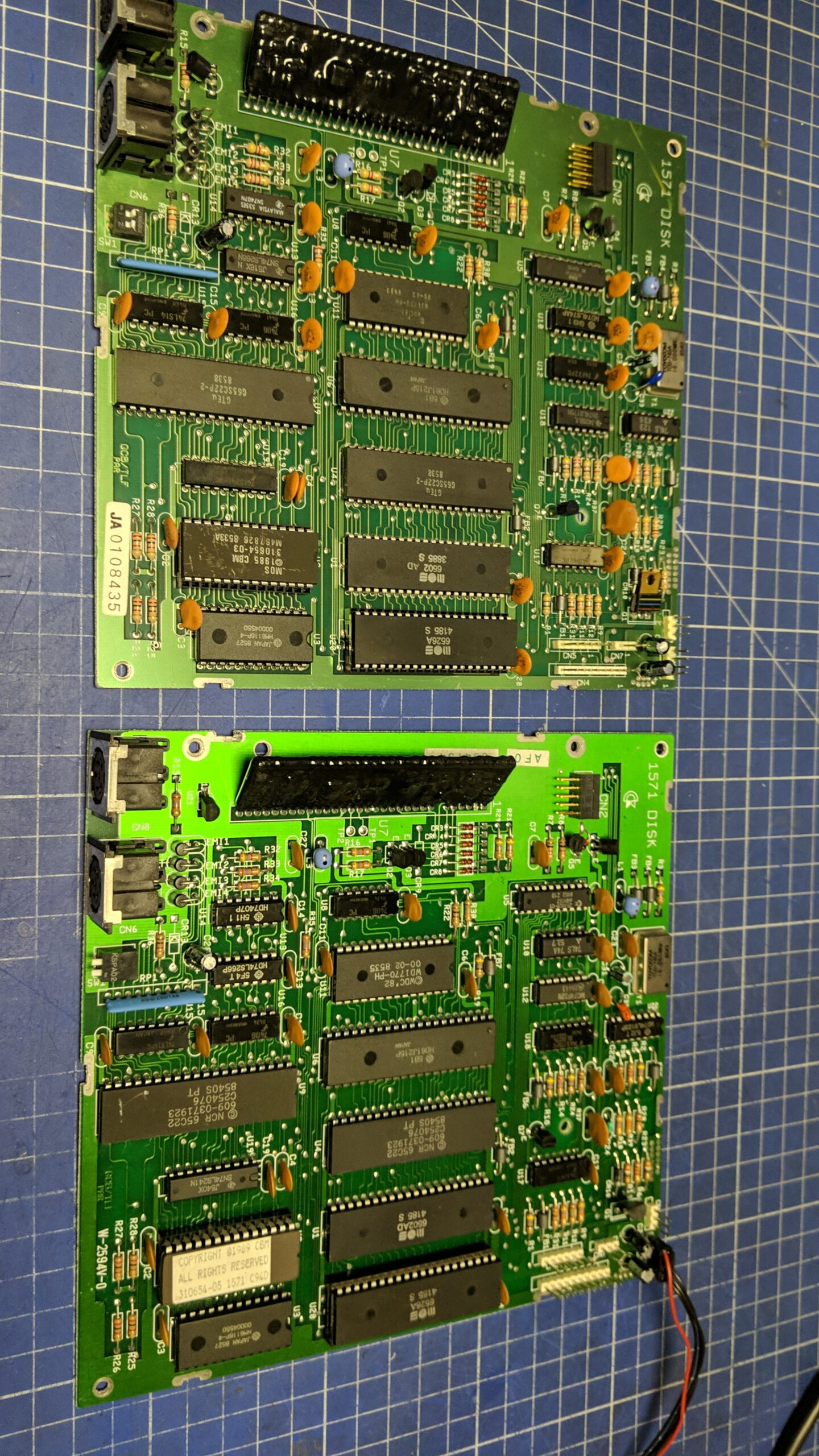
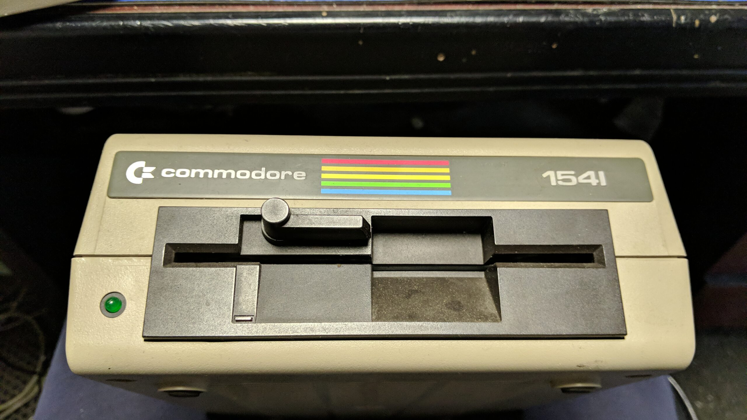
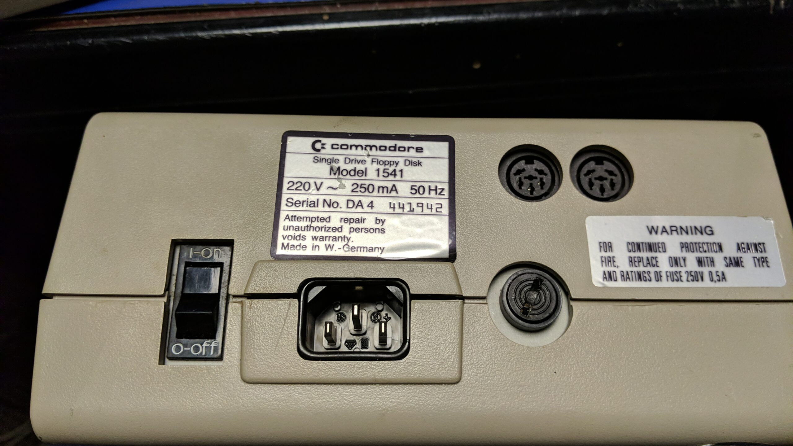
6x 1541
There were six 1541s left to sort out. Four of those drives were not reading disks or were not visible under the C64 system. Two of them were actually working as it turned out, it only had ID set to 9. In the case of 1541s, ID is not set with the DIP switches like with newer drives but by cutting/soldering a pad directly on the PCB. One PCB had this pad destroyed so I had to rebuild the connection and secure it with UV resin.
After fixing issues with IDs, I ended up with four drives (out of six) working. I’ll skip pics with cleaning, re-capping, etc. as this was covered in a previous post already.
All of the drives needed an alignment and speed adjustment. This is a bit harder with Alps drives but doable. Harder, because I find the Alps drives more picky and sensitive to motor moves.
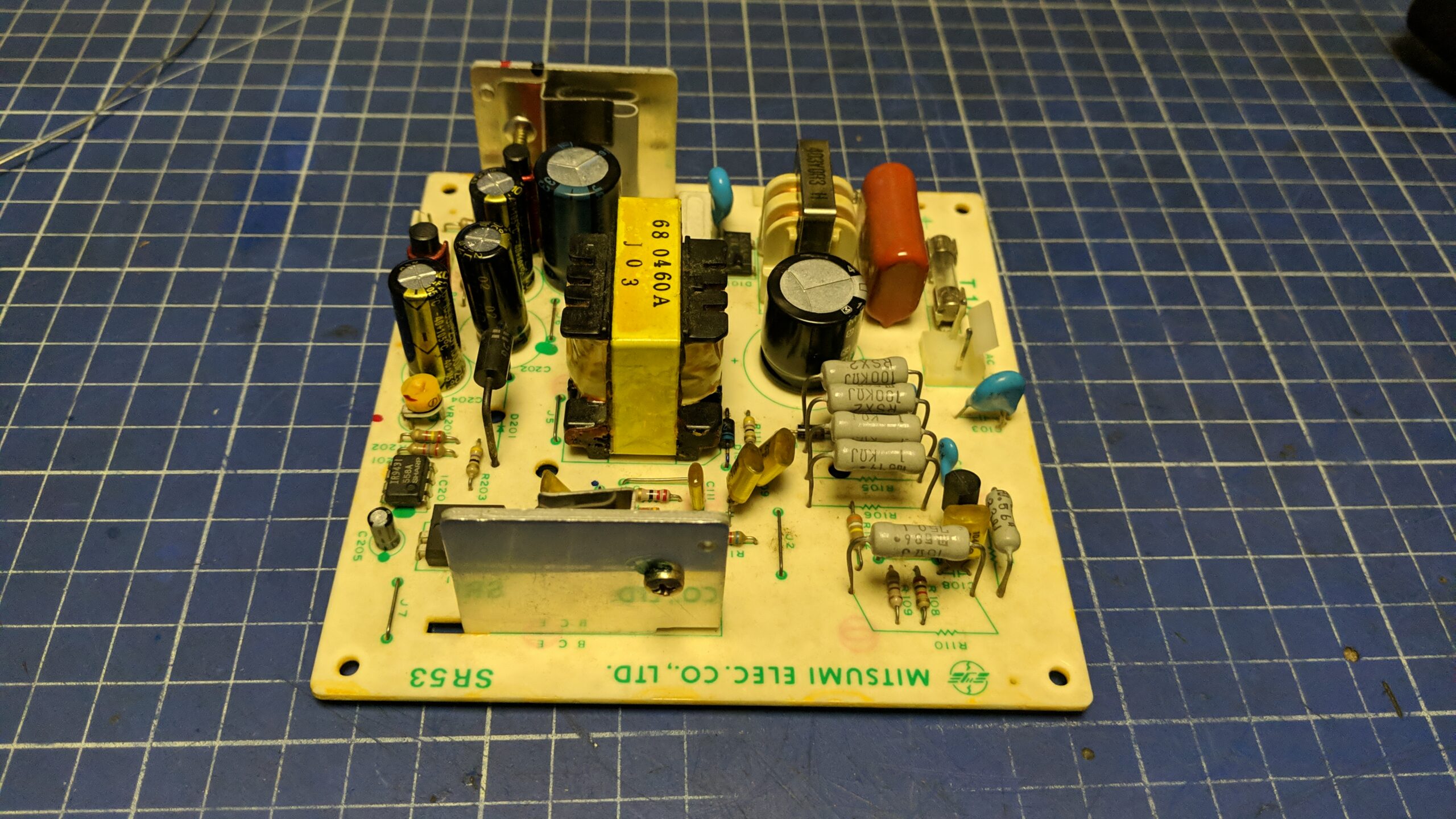
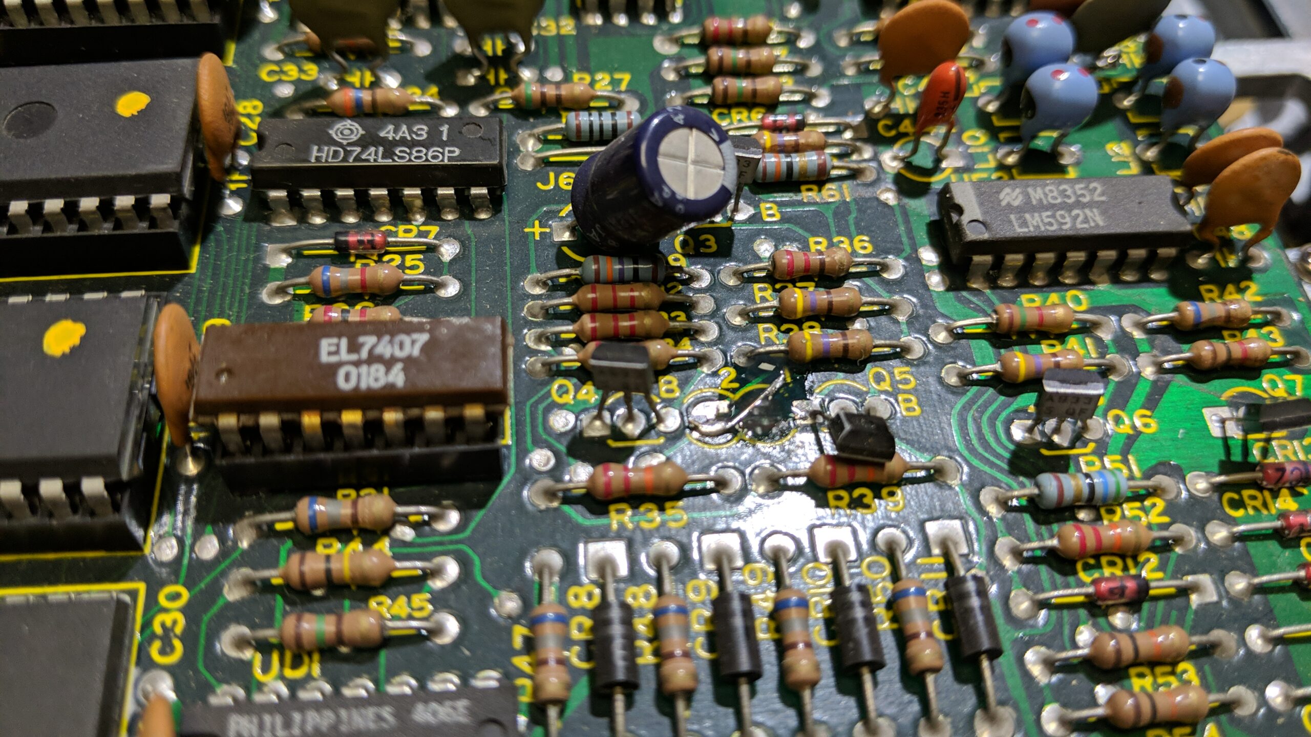
Re-capped with standard electrolytic caps as I didn’t have radial caps at hand.
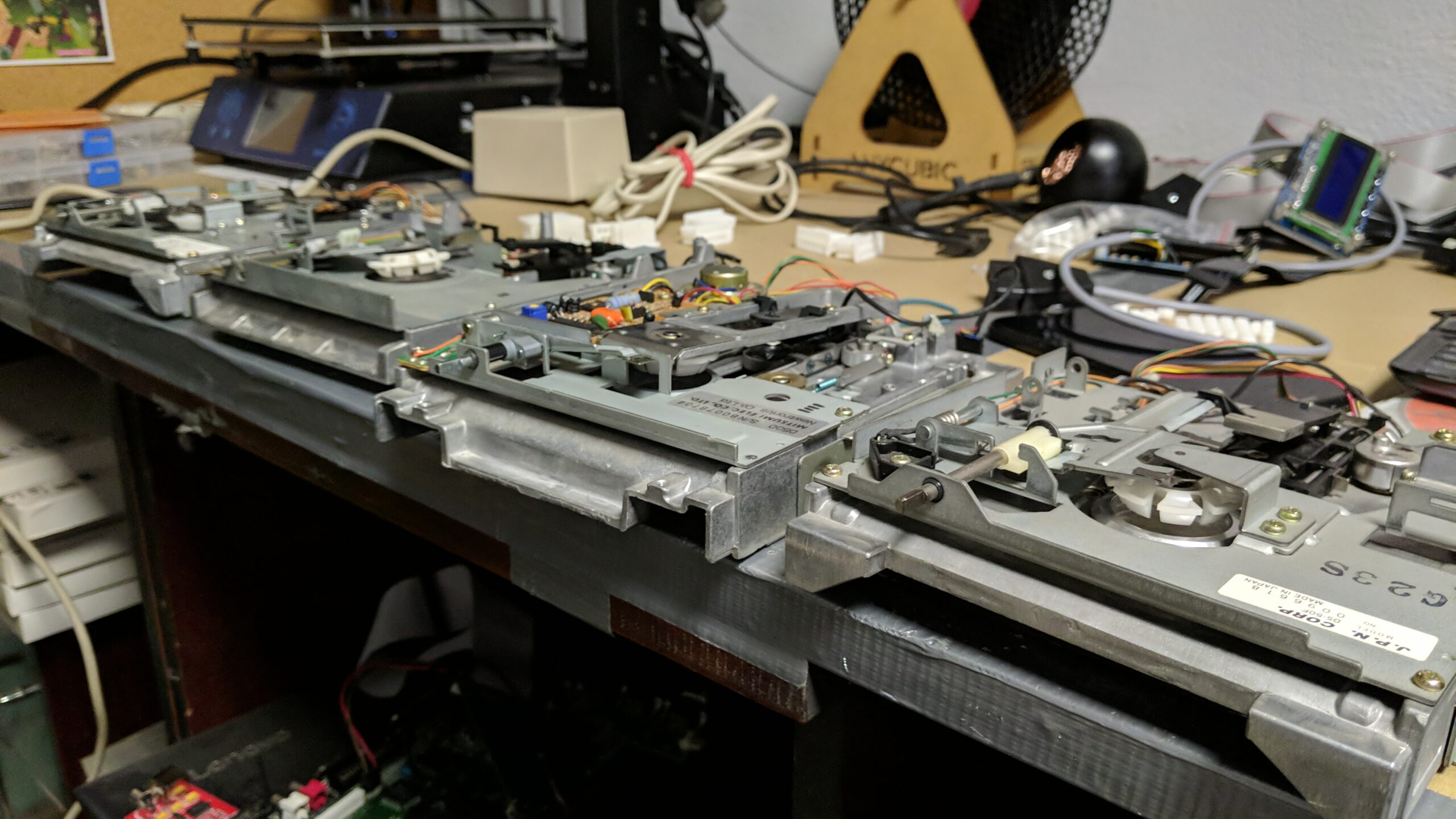
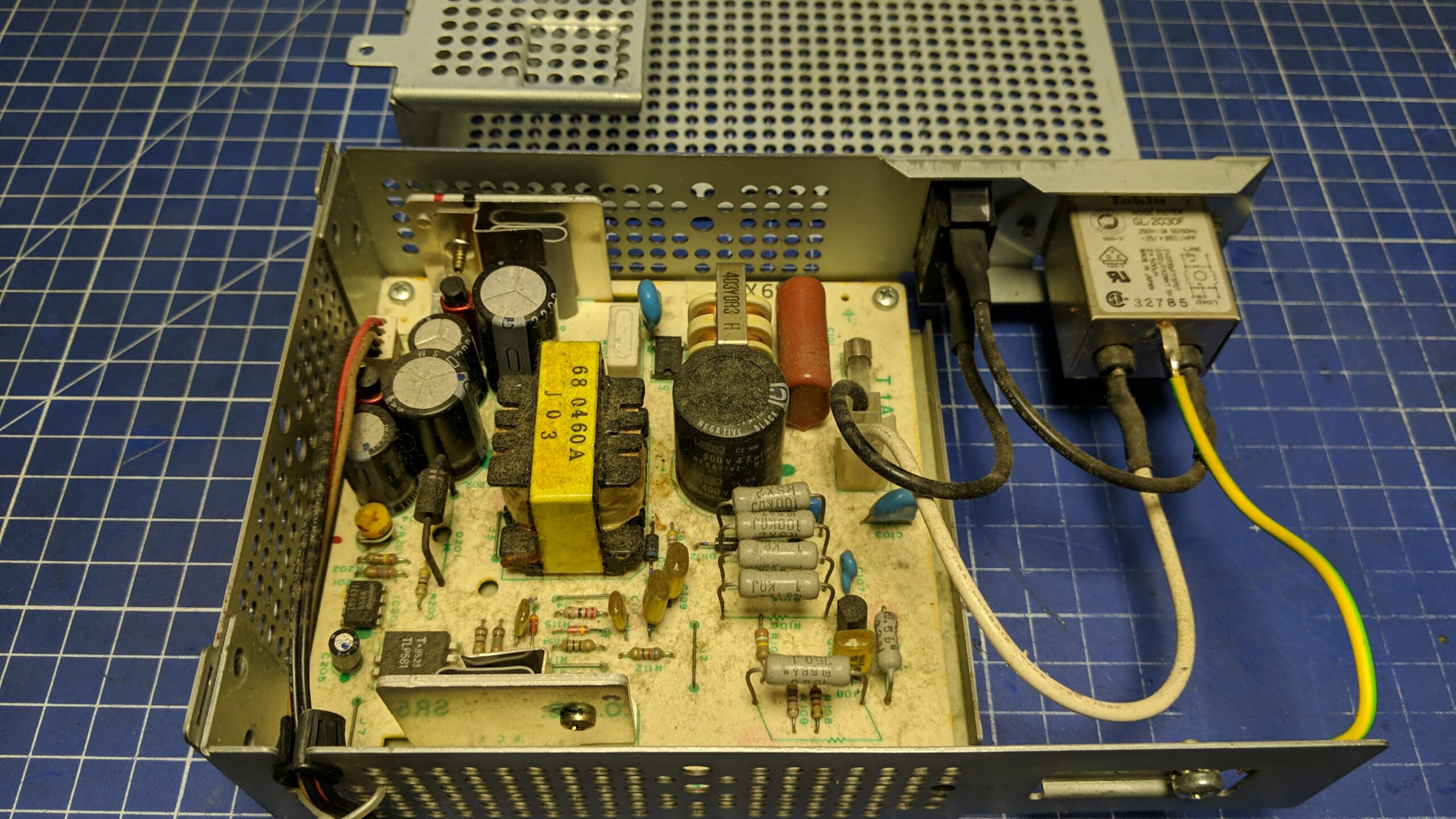
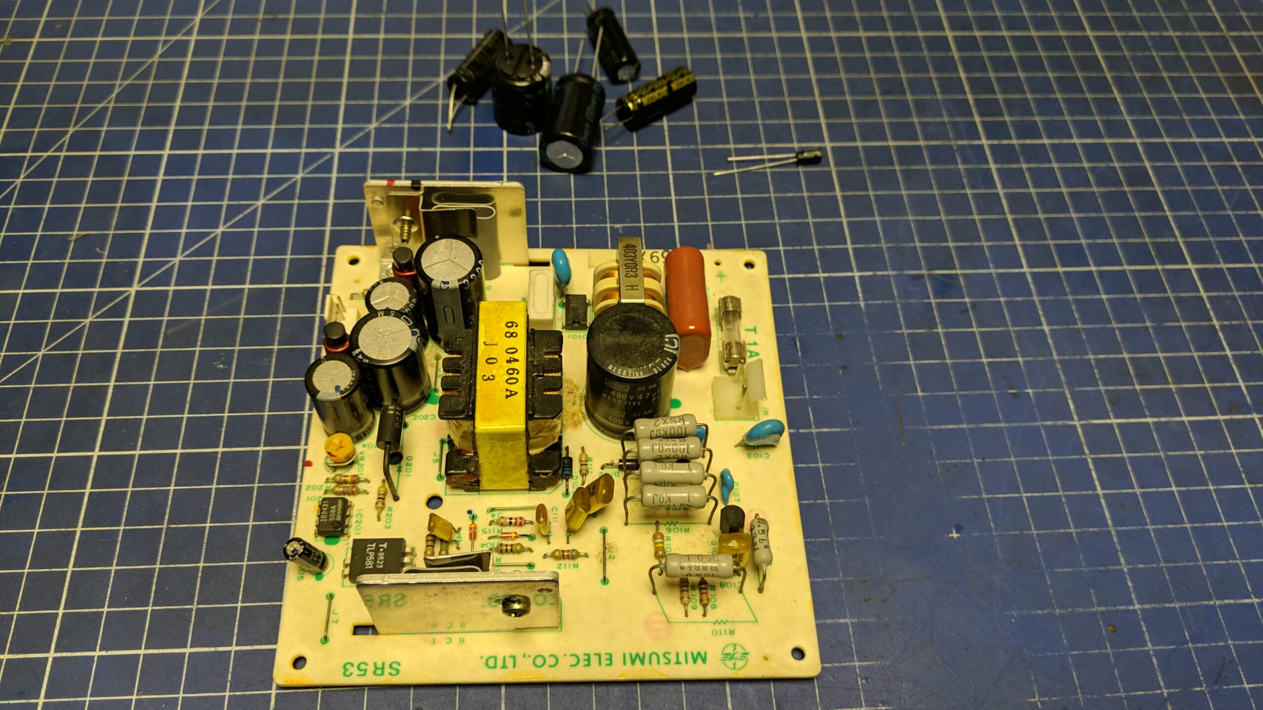
The last two drives
After all the above, I ended up with two non-working Mitsumi drives.
I guess you already know where this is heading 😀
The PCB and PSU were working fine as I’ve tested it with other working drives.
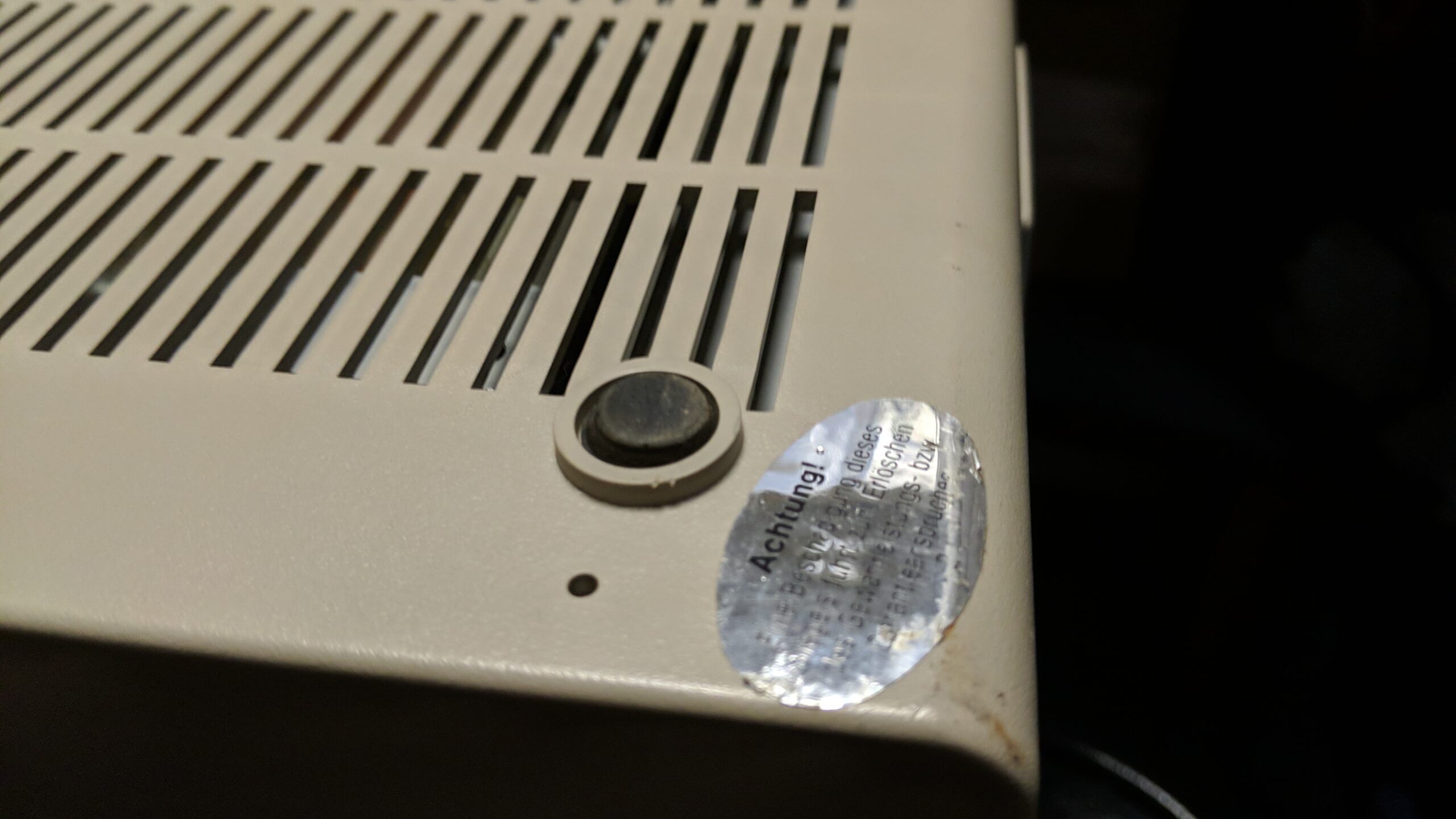
Interestingly enough, one of the Mistumi drives is brown like the Alps and it had an original “Warranty void” sticker. I didn’t see any such drive yet.
Back to the coils
As you probably suspect, both drives have a burned coil inside an R/W head. I’ve described how to check if it is burned in Episode One.
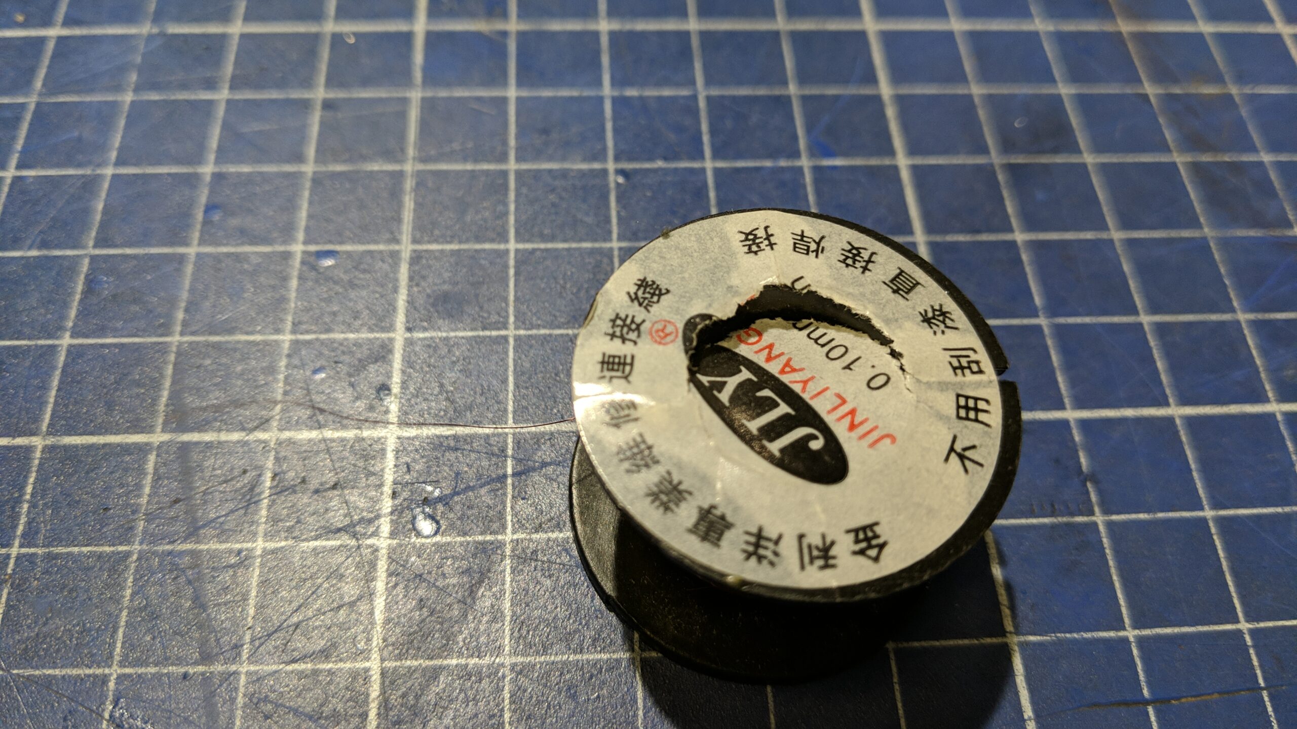
I have a new microscope with LCD so I thought, I’ll give it a go and try to rewind the coil. I even bought a proper wire for this task.
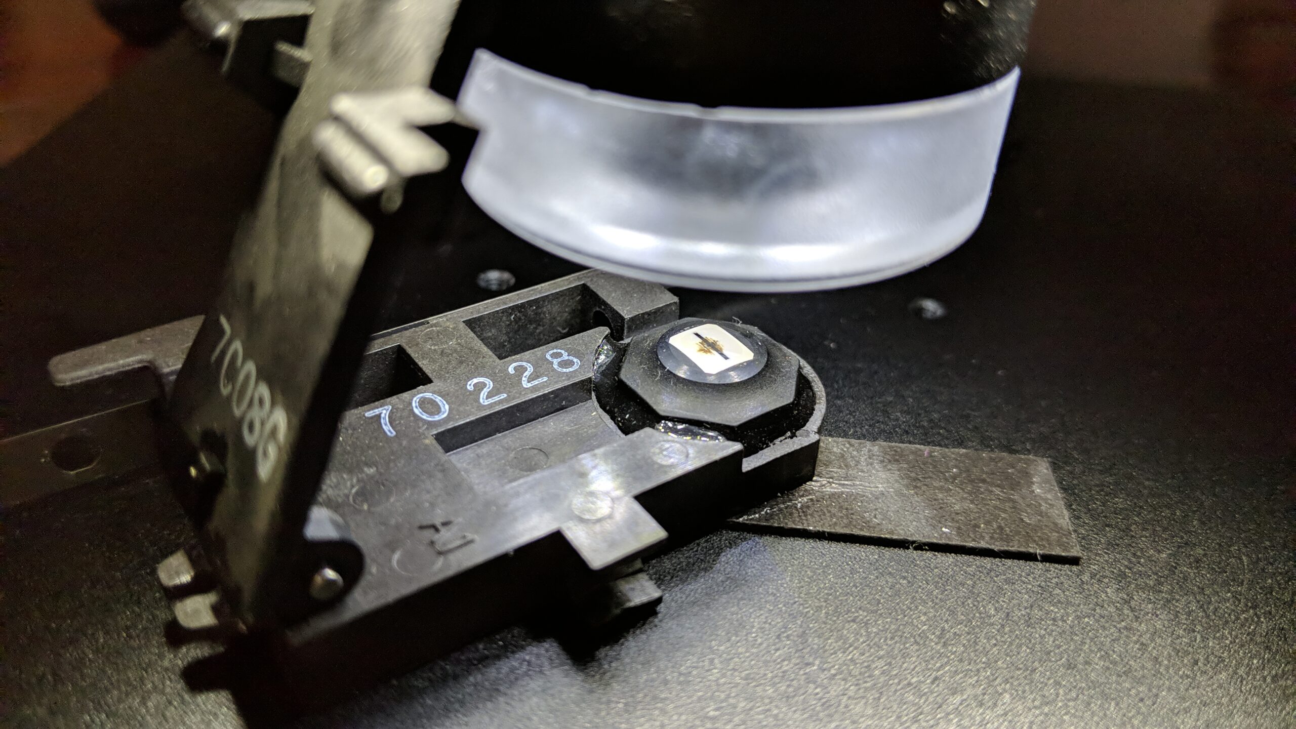
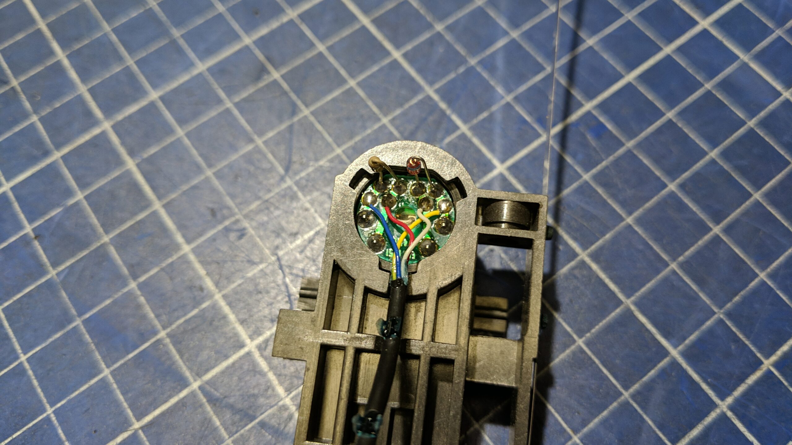
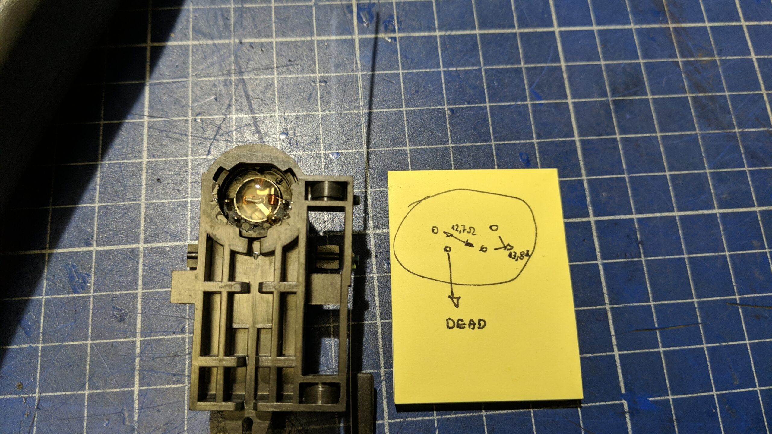
When I removed the whole head assembly I noticed that it is dirty and covered in rust.
Next, I desoldered the small PCB and checked which coil is burned with a multimeter
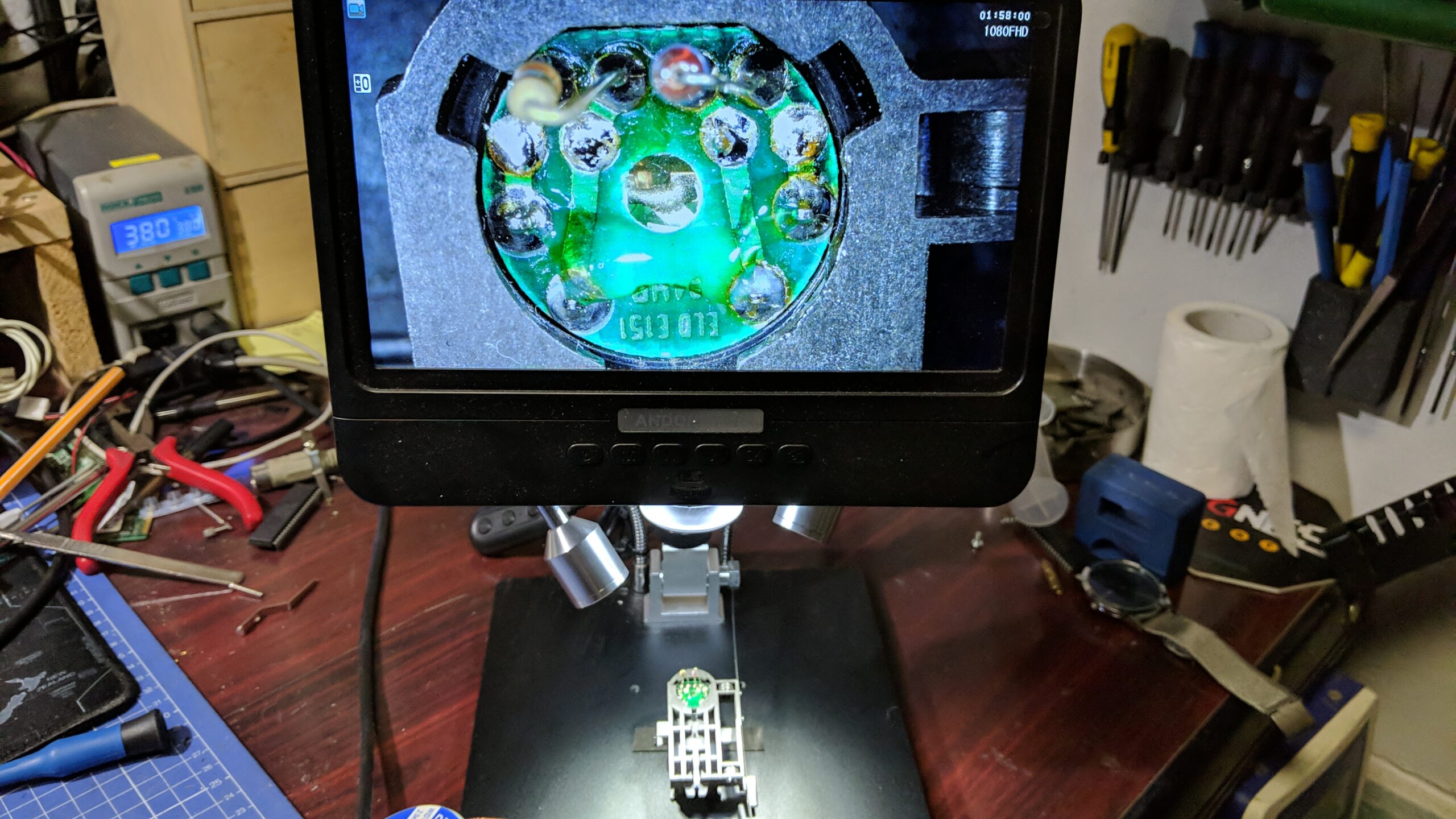
The plan was to remove the whole silicate protective filling first and then try to remove the coil and rewind it outside. I knew it is going to be a tedious job so I figured that I will record the whole procedure with my microscope as it supports recording. I wanted to make a nice time-lapse movie out of a gathered recording.
I’ve inserted the SD card and started to work. I’ve used tiny tools to remove silicate compounds. The process took at least 3 hours as I didn’t want to damage anything but silicate. This is the moment when I realized that the SD card wasn’t properly inserted which means it didn’t record anything …

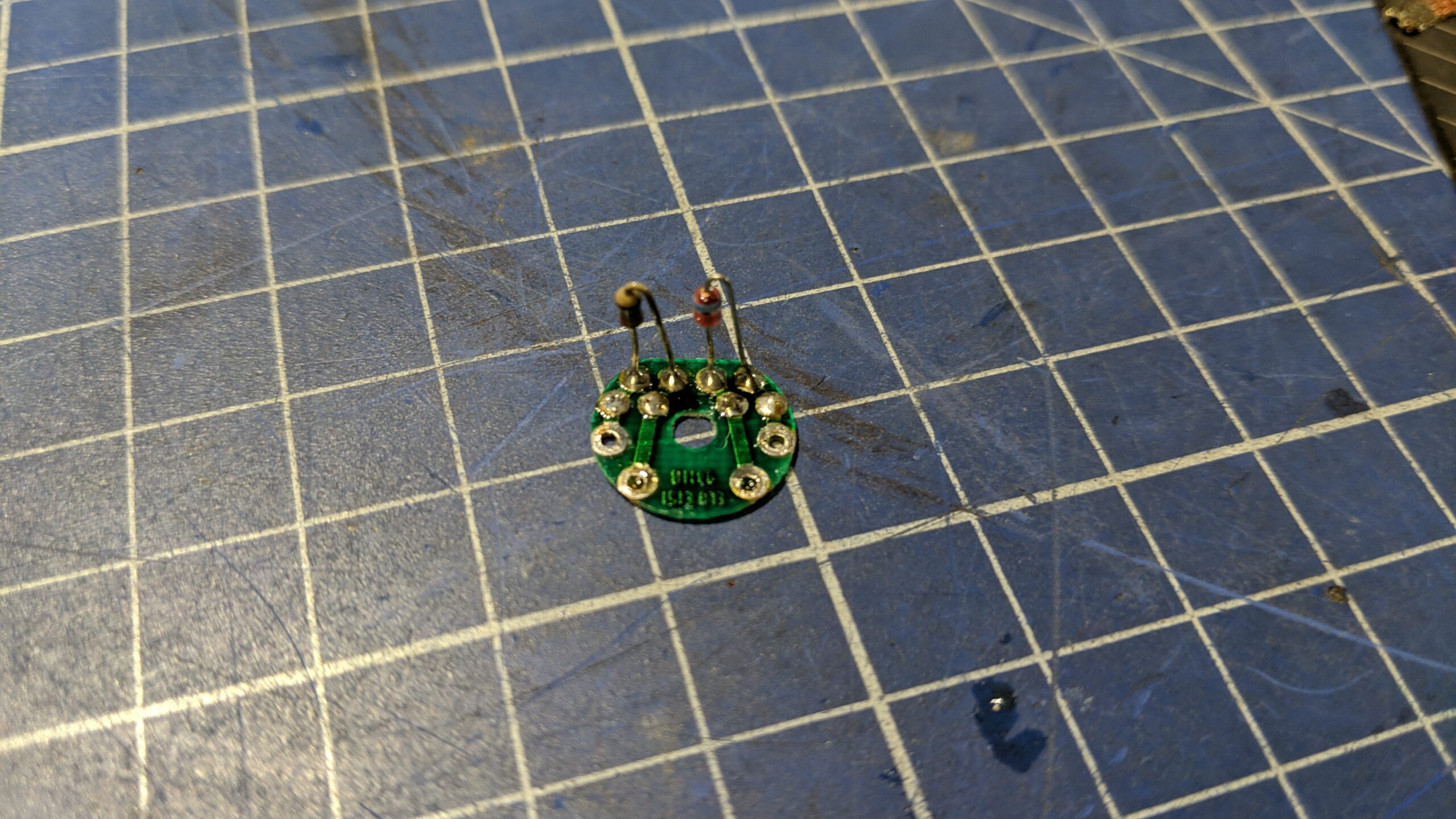
At least I had some shots that I took with another camera near the end of the process.
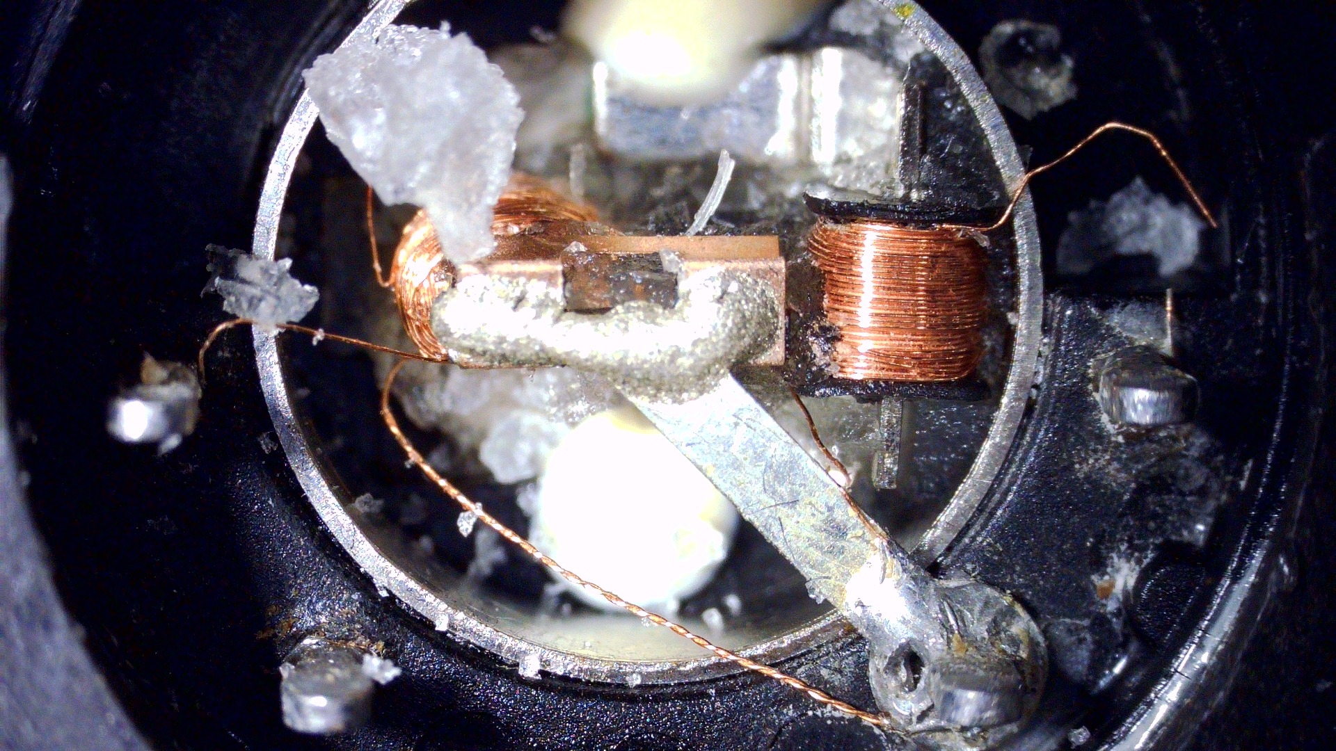
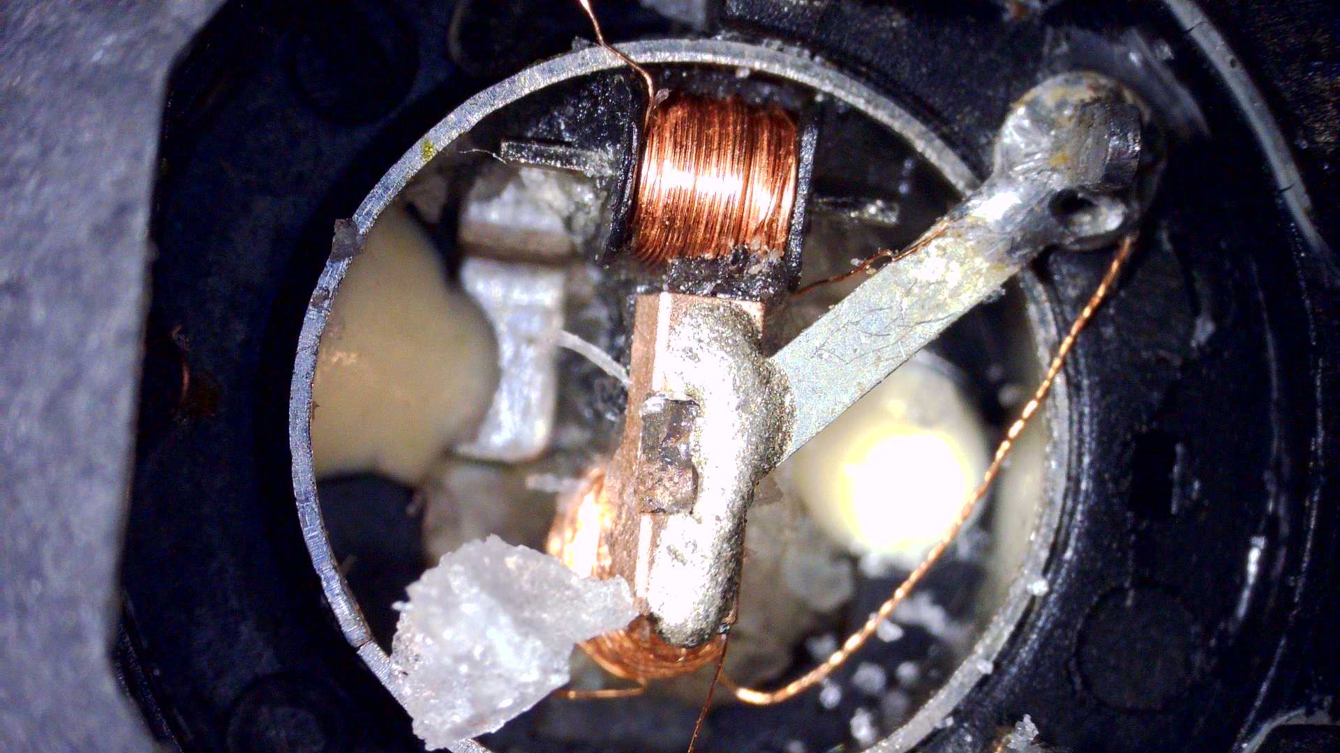
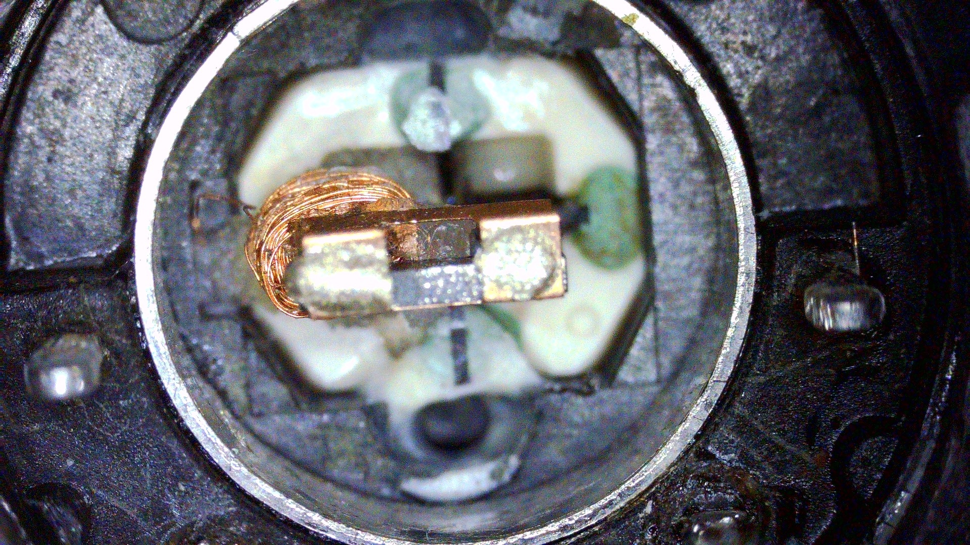
Below are two pics after desoldering the top GND strip of metal and removing the coil.
Final conclusions
After all that work was done, I realized these heads cannot be repaired without some sort of a very precise, computer-controlled robot. There is no way to remove coil from a ferrite core.
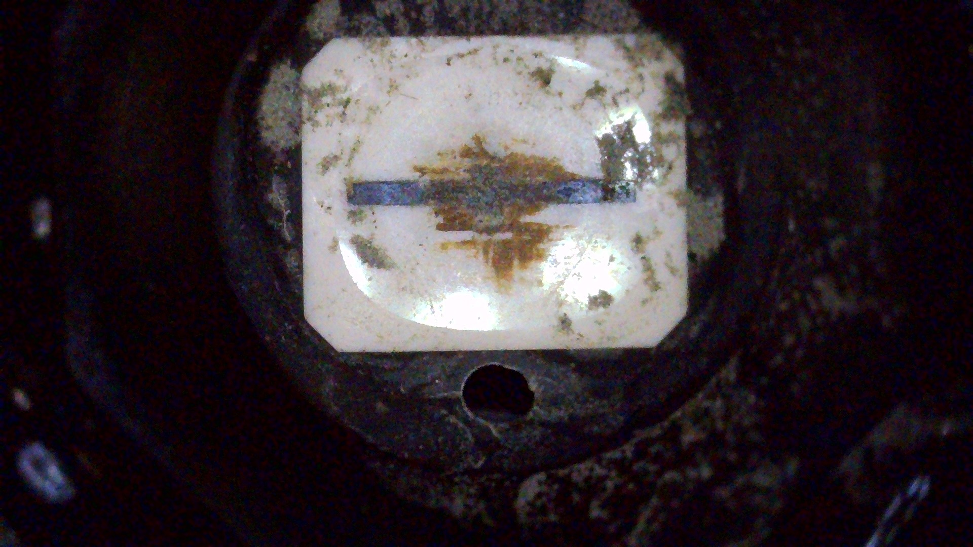
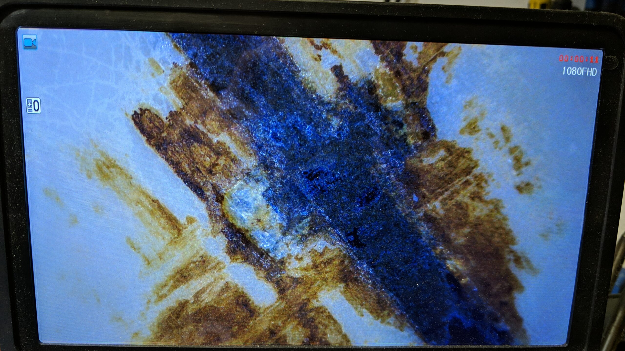
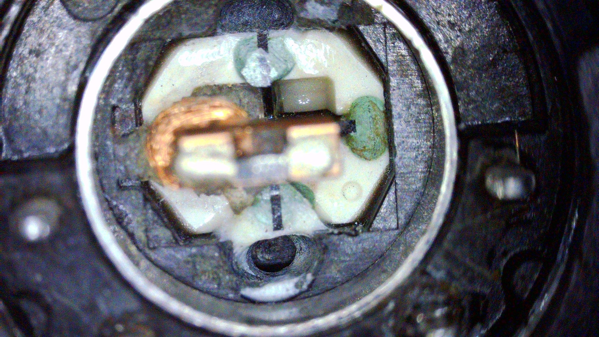
There is one more pic I took that explains it all.
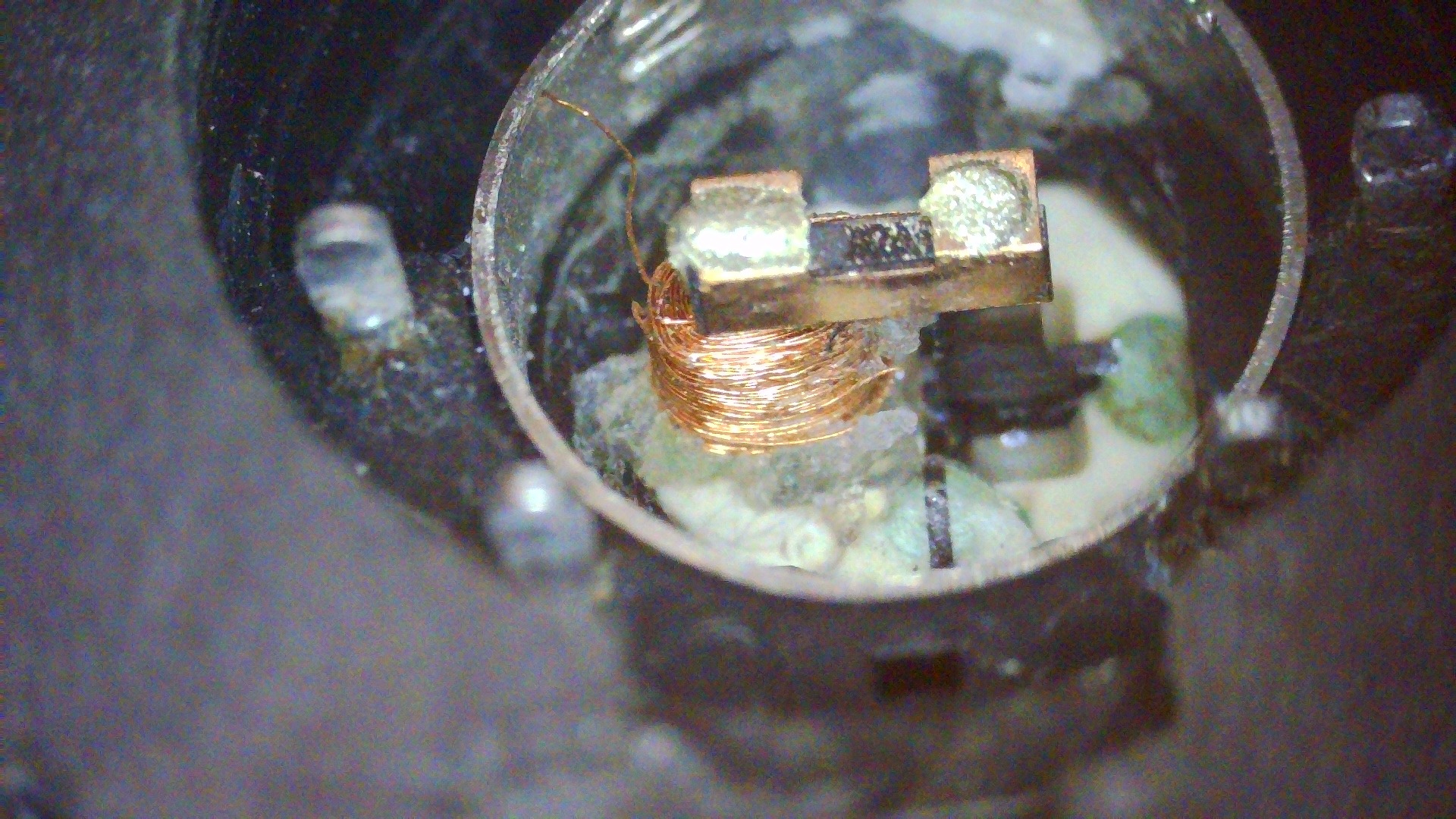
Simply put, the way the head was manufactured prevents removing the coil. I didn’t notice it while working on it in the previous post because the ferrite core broke off there. This time, I’ve managed to keep it all in place and it is now obvious that the ferrite core with a coil was partially submerged in an epoxy (the white thingy), then it was cut and polished forming the front of the head.
In other words, sadly the coil has to be rewound in place and this might be a very challenging task without a CNC robot of some kind.
Another idea is to try to replace the whole head with a chip with a magnetic detector. I will be researching this idea.
Commodore floppy drive fixing final status is – 12 drives fixed, 2 to go 🙂
See you in the next post 🙂
Outro
If you want to get the retro gear I am manufacturing or hardware modules, please visit shop -> https://retrohax.net/shop/
Please support my work by commenting here, and on my Facebook, Twitter, Reddit, and other social media platforms.

Thanks for this article. It will be helpful when I’ll be trying to repair my 1571 (victim of some past flooding with heavy corrosion on PCB).
Great article. I just went thru this myself, pulled apart the head and found it humanly impossible to rewind without some sort of fine machinery as you stated. Oh well!
Thanks! Yeah, I was thinking about some sort of a CNC rewinding machine. I cannot see any other option if someone wants to restore it to original form.