… or I just had a few spare hours 😉
<intro>
From time to time I feel a need to work on something else than refurbs and repairs, so this time, I have another fun project to cover that I’ve worked on some time ago. I’ve worked on similar projects before and even documented ’em all here on the blog.
The first attempt was an interesting journey – https://retrohax.net/project-retroblade-v-0-27237-part-one-2/ but later I did some upgrades which resulted in a way better outcome – https://retrohax.net/project-retroblade-evolution-part-two/
I had a few spare hours the other day and below you can see the results 🙂
</intro>
I started by dumping all items on a table that I’ve gathered during the past months. Well, maybe not all but only the most interesting stuff 🙂
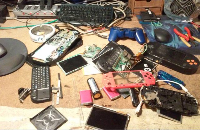
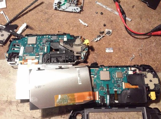
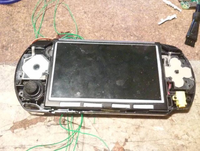
I had two Sony PSP handhelds and both were broken in some way. My idea for this project was to use a PSPs case and put RPI Zero inside along with all other parts that would form a fully functional retro platform. I wanted to use awesome RetroPie as in previous projects.
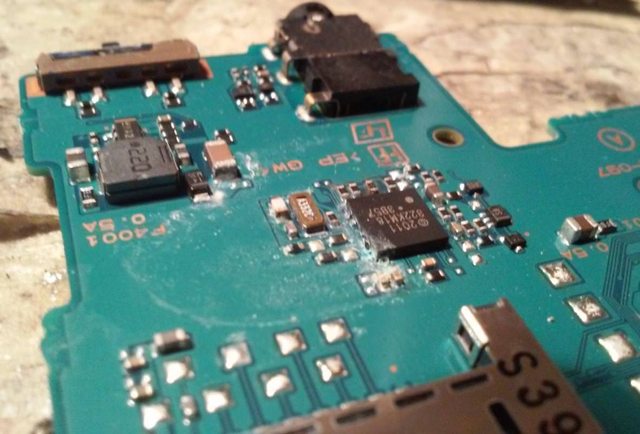
One of PSPs mainboards had shorted chips after some sort of liquid spillage.
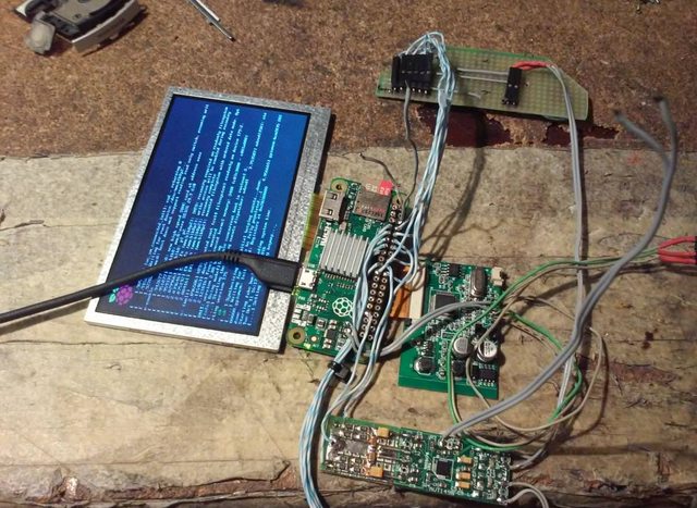
Initial hardware tests. I’ve taken some parts out of the 7″ RetroBlade that I’ve created some time ago but I simply didn’t like it so it had to go 😀
Checking if a 5.3″ LCD will fit into a PSP case.
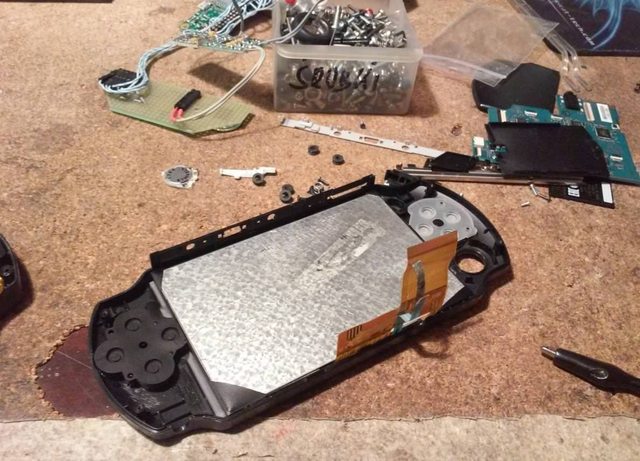
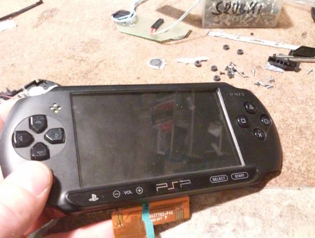
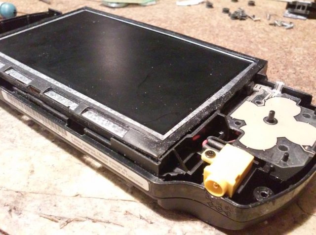
Woohoo! Perfect fit 🙂
Next, I’ve started to put other modules, like this Dell servers PERC li-ion battery.
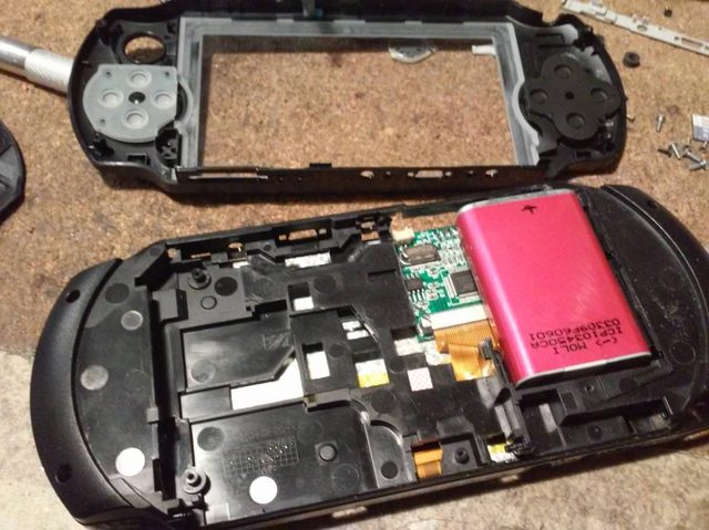
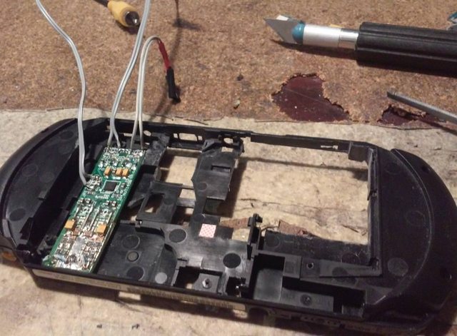
Amplifier module along with a pre-circuit to get sound from Rpi Zero via PWM
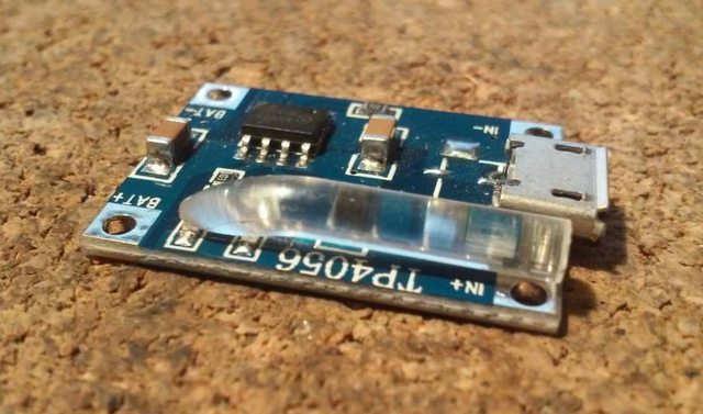
Charger
Tiny USB-powered Li-Ion charger with my dirty hack to deliver LED light to an edge. It was made out of transparent 3D printing filament lol.
Pads hack
I’ve realized that It would be cool to use and connect original pads to RPI Zero. That turned out to be a quite challenging task.
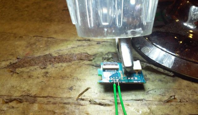
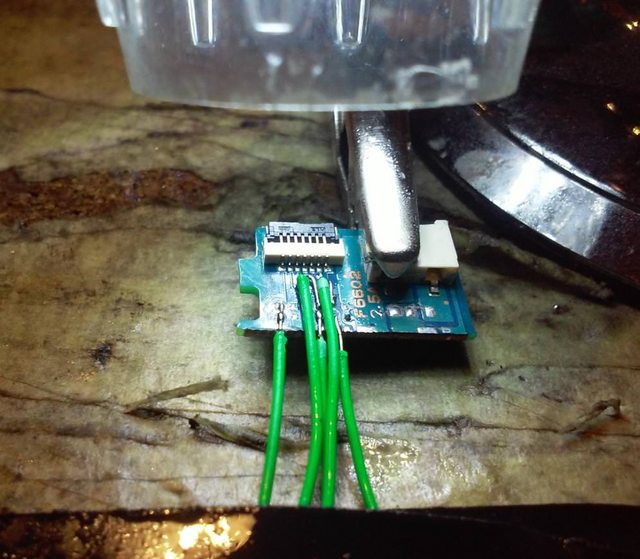
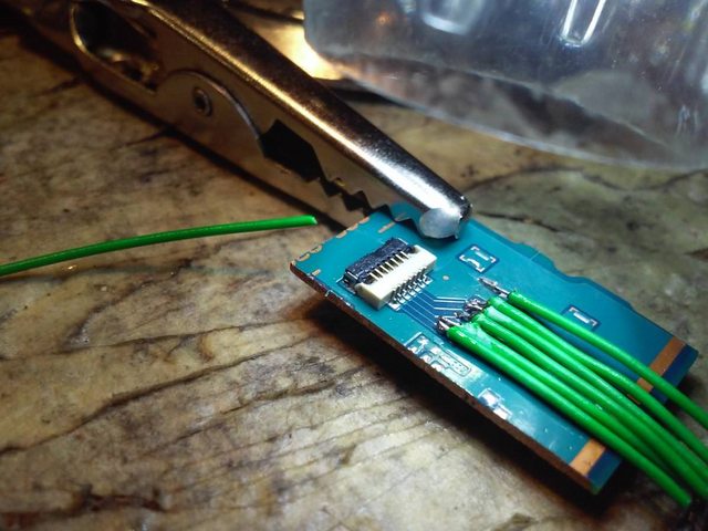
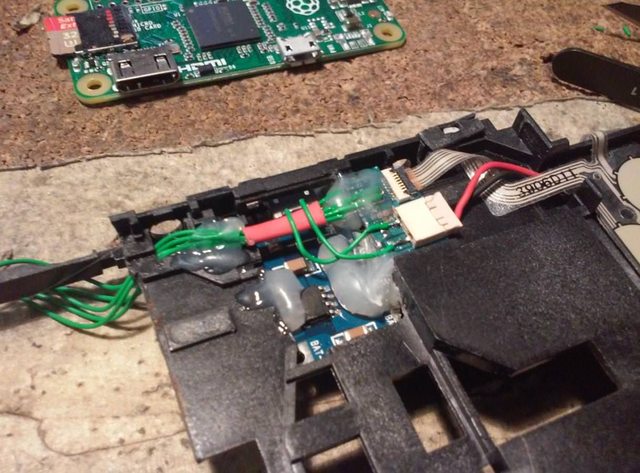
My idea was to cut a piece of the mainboard with a ZIF connector in it and then solder wires directly to a PCB.
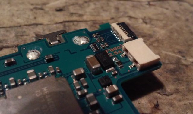
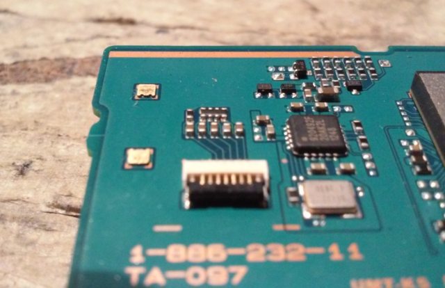
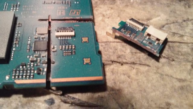
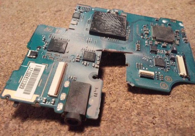
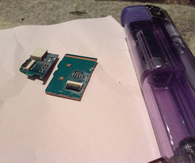
Now, here is the tricky part 🙂
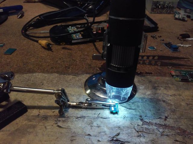
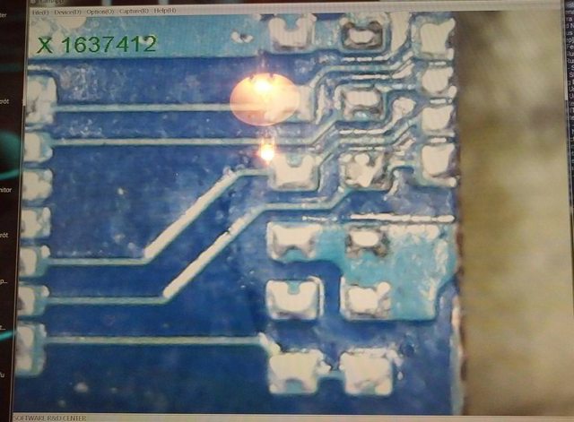
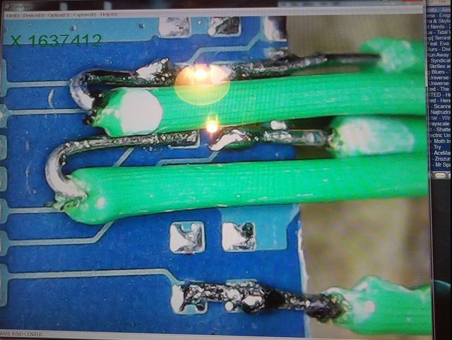
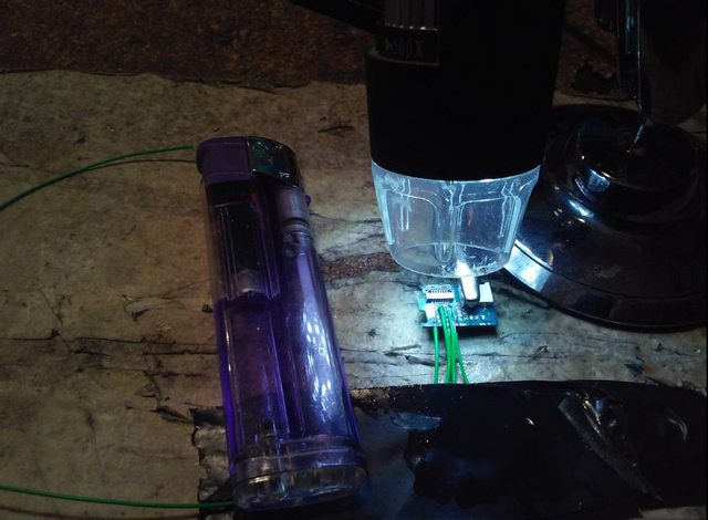
I had to use my USB camera to solder all tiny Kynar wires to pads on PCBs.
… kinda hard task after having three coffees lol.
Here is a cigarette lighter to give you an idea of how tiny these wires and pads are.
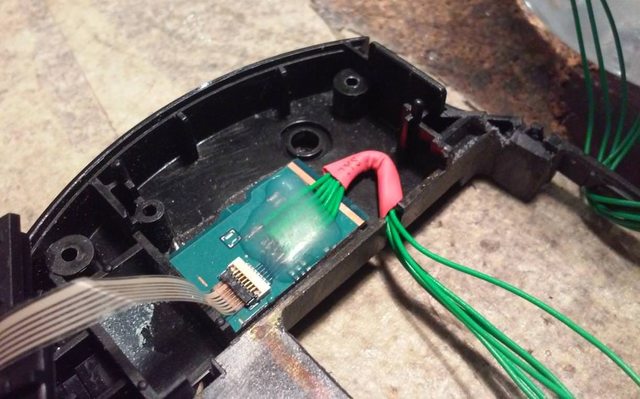
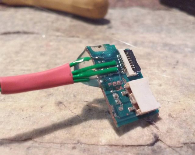
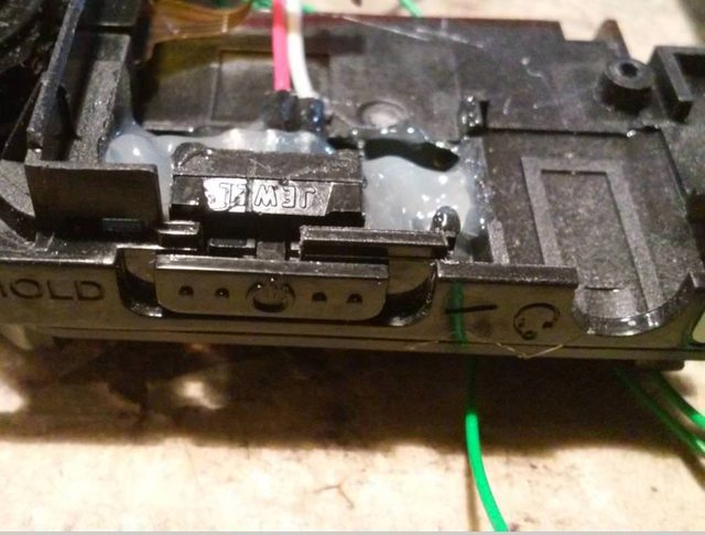
I then secured wires with hot glue and shrink wrap.
Power switch and other stuff
I’ve also used an off-shelf power switch because the original was a momentary switch and would simply not work with my setup.
The new switch fits perfectly.
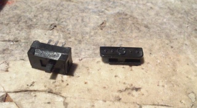
Time for another round of measurements and tryouts.
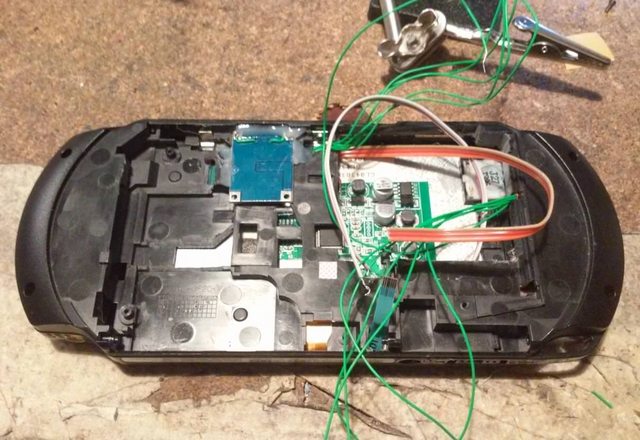
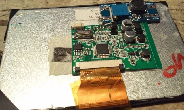
While trying to run the whole system off a battery, I noticed some voltage drops. I had to crank up the voltage a little bit because LCD didn’t sync correctly.
I chose a standard voltage step-up converter.
Testing again, but this time with RPI Zero on board.
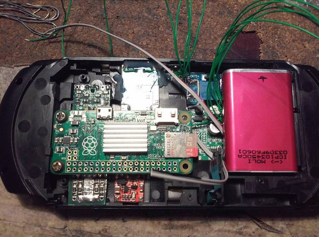
I’ve also finally managed to connect all flying wires.
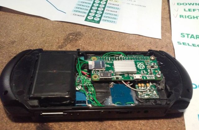
First boot
First time booting and obligatory LAMERS demo 😀
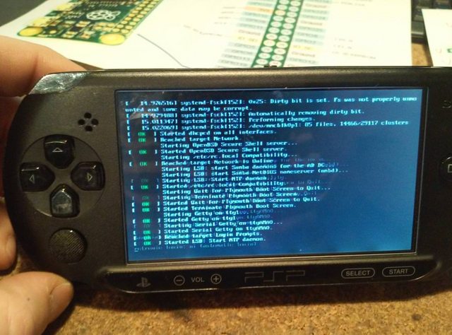
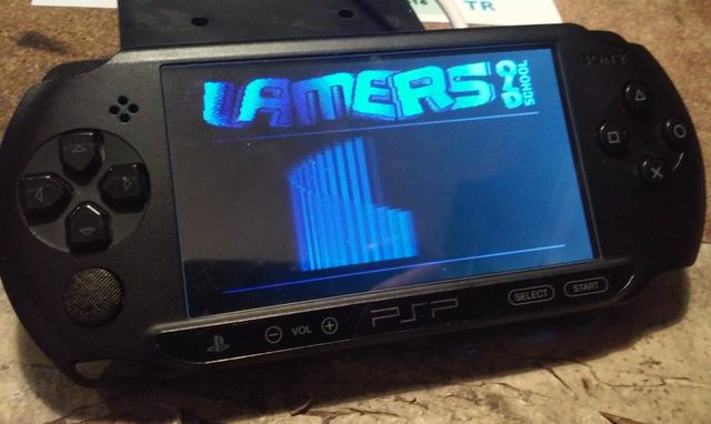
Fail
At this point, I thought that I am done. The only thing left to be done was to put back-cover … aaaand

It turned out that the back cover will not fully close because the battery was too thick lol.
However, that case wasn’t fully lost because right after realizing the above failure I noticed a pile of old Nokia cellphones lying around …
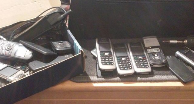
Instantly I was like …

Here is what followed.
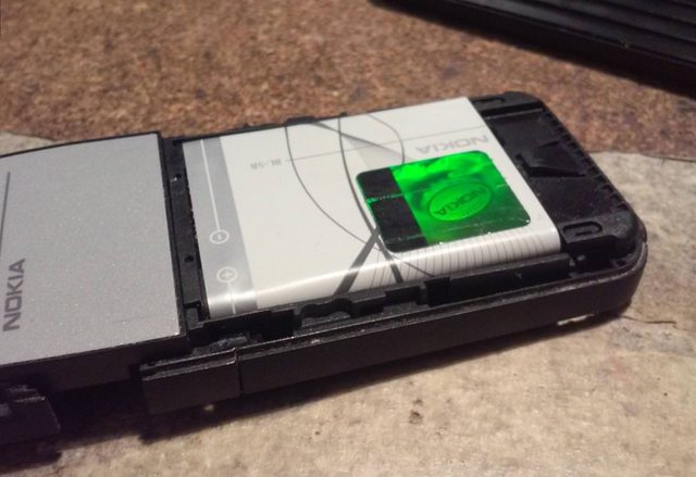
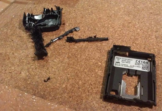
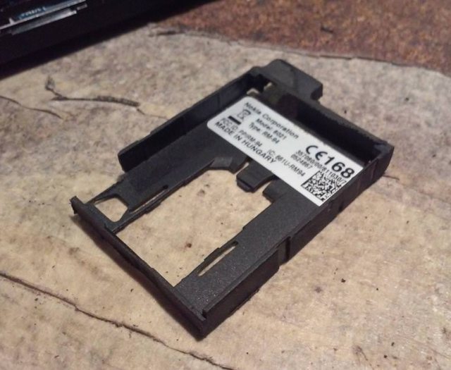
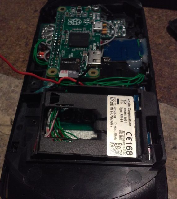
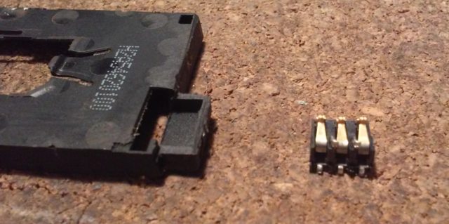
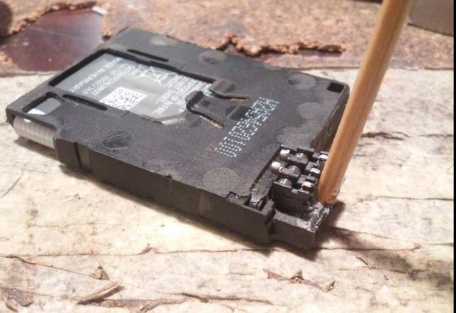
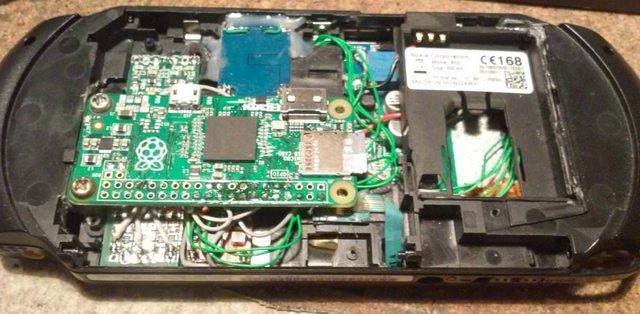
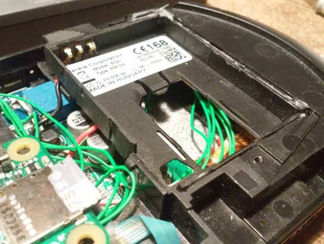
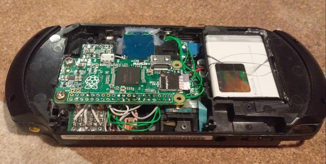
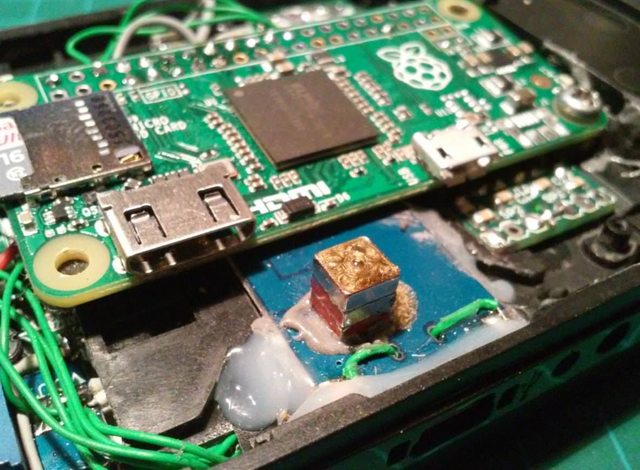
Now, with proper clearance, I was able to install small magnets to keep both parts of a case in place.
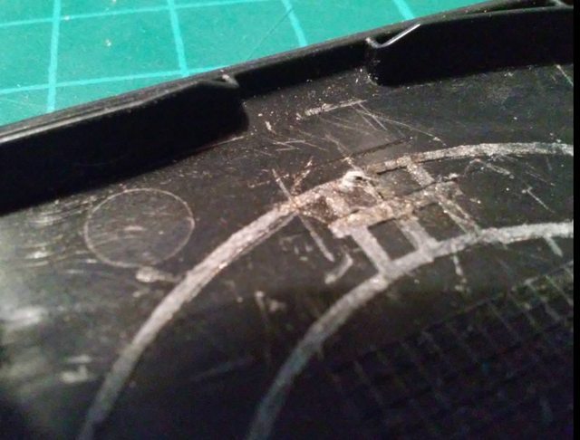
TAAADAAAAA!!! Case literaly closed lol ;D
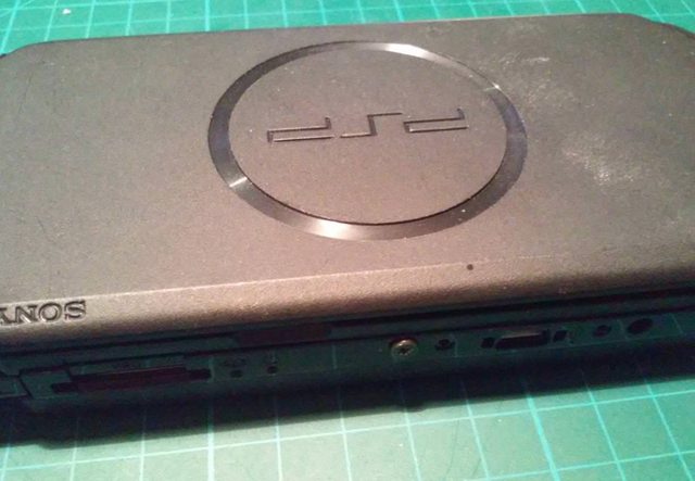
Some final testing and that’s it! 🙂
OUTRO
If you want to get retro gear or hardware modules, please visit our shop
New products are added every month.
Also, please support our work by spreading info about it.
Without your support, we simply cannot grow and we have a lot of new excellent retro hardware (and more) products to come

