… or how to make use of rear camera LCD
Soooo…
…so it all started because I browse too much Interwebz :>
Like this:
Nowadays, the electronic stuff is really cheap so very often when I find something cool, I buy it without hesitation but once it’s delivered I don’t really know what to do with it lol.
That was exactly the case with 3.2-inch TFT which was supposed to work with Raspberry PI or with Arduino MEGA2560 connected via a dedicated shield.
Here is a TFT LCD that I’ve bought: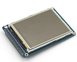
https://www.sainsmart.com/sainsmart-3-2-tft-lcd-display-touch-panel-pcb-adapter-sd-slot-for-arduino-2560.html
My initial idea for it was to use it as a screen for the 3D printer which happens to be powered by Mega2560, so I’ve ordered a shield as well.
However, I forgot that I will not be able to connect such an LCD through a shield because I already have one shield connected (RAMPS), plus I am a total idiot …. just like that ;P.
So that cunning plan died instantly.
I was like:
Damn, maybe RPI then?
Going back to the Interwebz was inevitable …. and it took quite a while before I figured it out.
Problem was that this specific LCD had a parallel input interface and RPI 1 doesn’t have enough GPIOs.
It had to go through SPI or a similar interface.
Two years ago there weren’t many tutorials and the community was not that large – I mean it was big already but not huge like nowadays 😀
Finally, I’ve found a decent place:
https://github.com/notro/fbtft/wiki
This whole FBTFT project is awesome!
However, it wasn’t that popular back then, with all the nice details and descriptions.
These days on a project’s website, You can find schematics of the SPI interface to connect LCD such as mine to RPI 1 and all other stuff.
https://github.com/notro/fbtft/wiki/SPI-interface-circuit
All necessary drivers and scripts can be found there too.
Anyway, I’ve managed to build my own SPI interface after a while … spider style 😉
RPI TFT 3.2″ OWNZAAAH from pit on Vimeo.
Getting the touch panel to work was done simply just out of curiosity since I didn’t need it.
https://github.com/notro/fbtft/wiki/Touchpanel
RPI + TFT LCD – Touchscreen WORKS !!! from pit on Vimeo.
If not for the 3D printer…
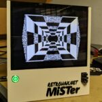
…then why waste time? hmm, good question! I was asking it myself for a while too ….. until I found this –> https://retropie.org.uk/
This project is OMGWTFMADAFAKINAWESOME !!!111one!1eleven!
It is a Raspbian-based distribution with a crazy number of emulators precompiled in it, a convenient EmulationStation menu for navigation, many other tweaks, and most importantly great and active community.
As it turned out later, finding this resulted in nearly two garage-years(sic!) of my spare time with my own project – Codename: RetroBlade handheld console with as many emulators as possible.
But let’s start from the beginning.
LCD? … Yeah but which one?
The idea was to build a handheld that is capable of displaying retro stuff via HDMI on large LCD telly and which would support wireless keypads like Xbox or Sony Playstation but it still had to remain pure handheld and to achieve that, I needed a proper LCD.
I started testing RetroPie on my RPI 1 and it was working fine on nearly all 8-bit systems. 16-bit systems, on the other hand, required a lot of tweaking and still were lagging a lot but RPI 2 was already announced so I knew that this problem will solve itself. Still, the major problem was choosing a proper LCD.
Of course, I had my 3.2″ Sainsmart already set up, and below you can see my early tests.
Project RetroBlade – Double monitor tests – HDMI/GPIO from pit on Vimeo.
Testing testing testing
In the meantime, I started to test various emulators. The early version of RetroPie required a lot of tweaking and configuration but it was alright since I am a Linux fan (18 years and counting:>)
This is what the first tests looked like:
Project RetroBlade – Work in progress … from pit on Vimeo.
Unfortunately, Sainsmart connected to SPI with its drivers took around 5% of precious CPU time and a bit of RAM which is essential for fluent emulation.
At that time, I was playing a lot with hooking various stuff to my retro car – a ’96 Nissan Patrol. One of those things was a 4.3″ rear camera monitor. It was powered by 12V obviously and supported composite video as an input.
Do I have to repeat myself and tell you where I figured all the following config out? … yes, yes toilet throne! 😀
Toilet thrones FTW! 😀
Since Raspberry PI has a composite output that plan seemed to be a perfect solution. As the desired side effect RPI switches to HDMI when connected and stays on composite as a default display when not.
That rear camera LCD proved to be quite a good compromise between quality and price.
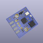
So not waiting too much I disassembled that Chinese-made rear cam and started to play around. It started to look promising but apart from that I still needed an amplifier for small headphone speakers. I’ve found quite a nice class D AVT amplifier kit.
Of course, I started to test it. I also hooked up a volume control circuit stolen from headphones.
Here is what it looked like:
Project RetroBlade – Work in progress 3 from pit on Vimeo.
Yup …
… end of part one. I’ll describe all other work and how this project evolved in future posts so stay tuned.

OUTRO
If you want to get retro gear or hardware modules, please visit our shop
New products are being added every month.
Also, please support our work by spreading info about it.
Without your support, we simply cannot grow and we have a lot of new cool retro hardware (and more) products to come 


One thought on “Project RetroBlade v 0.27237 – PART ONE”