… or I love Amigaaaaaaaaaaa!
Intro

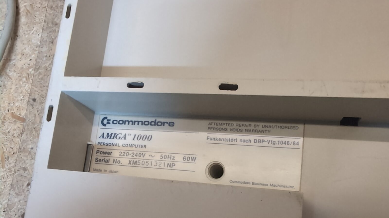
In this rather short post, I’ll show you how I’ve dealt with an iconic Amiga 1000 computer. It was a rather simple job, as the Amiga was in very good shape to start with.
The whole job was about cleaning, retrobrighting, fixing minor issues, and that’s it. There is no need to make this particular computer filled with upgrades. Instead, I’ve used an external device, but more on this later.
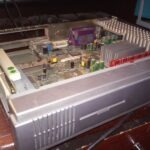
The state of the art and disassembly
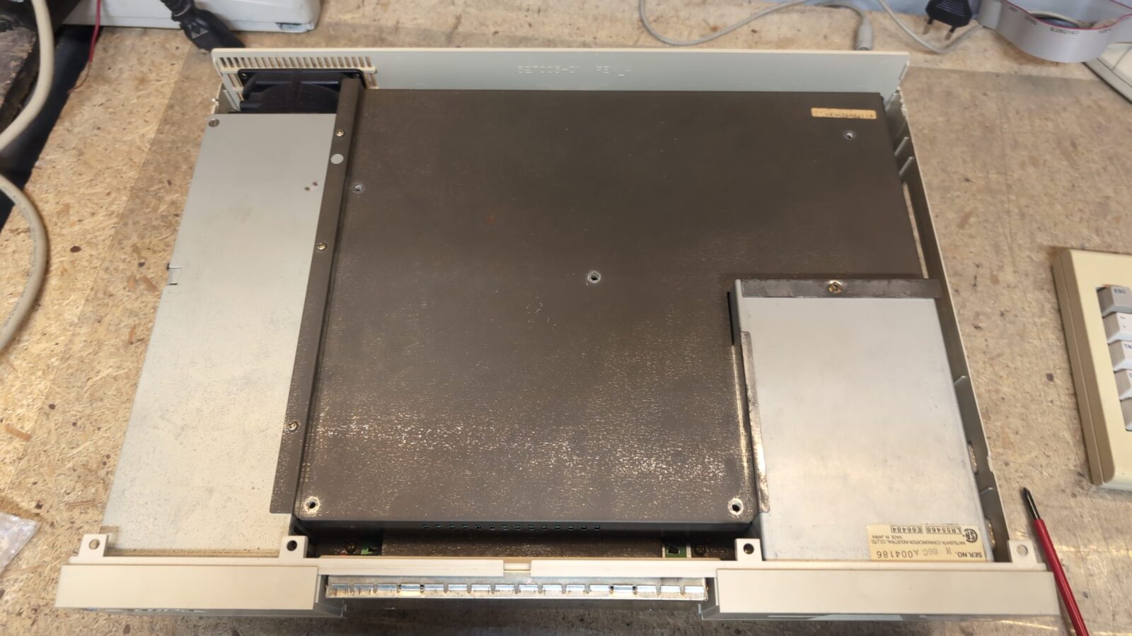
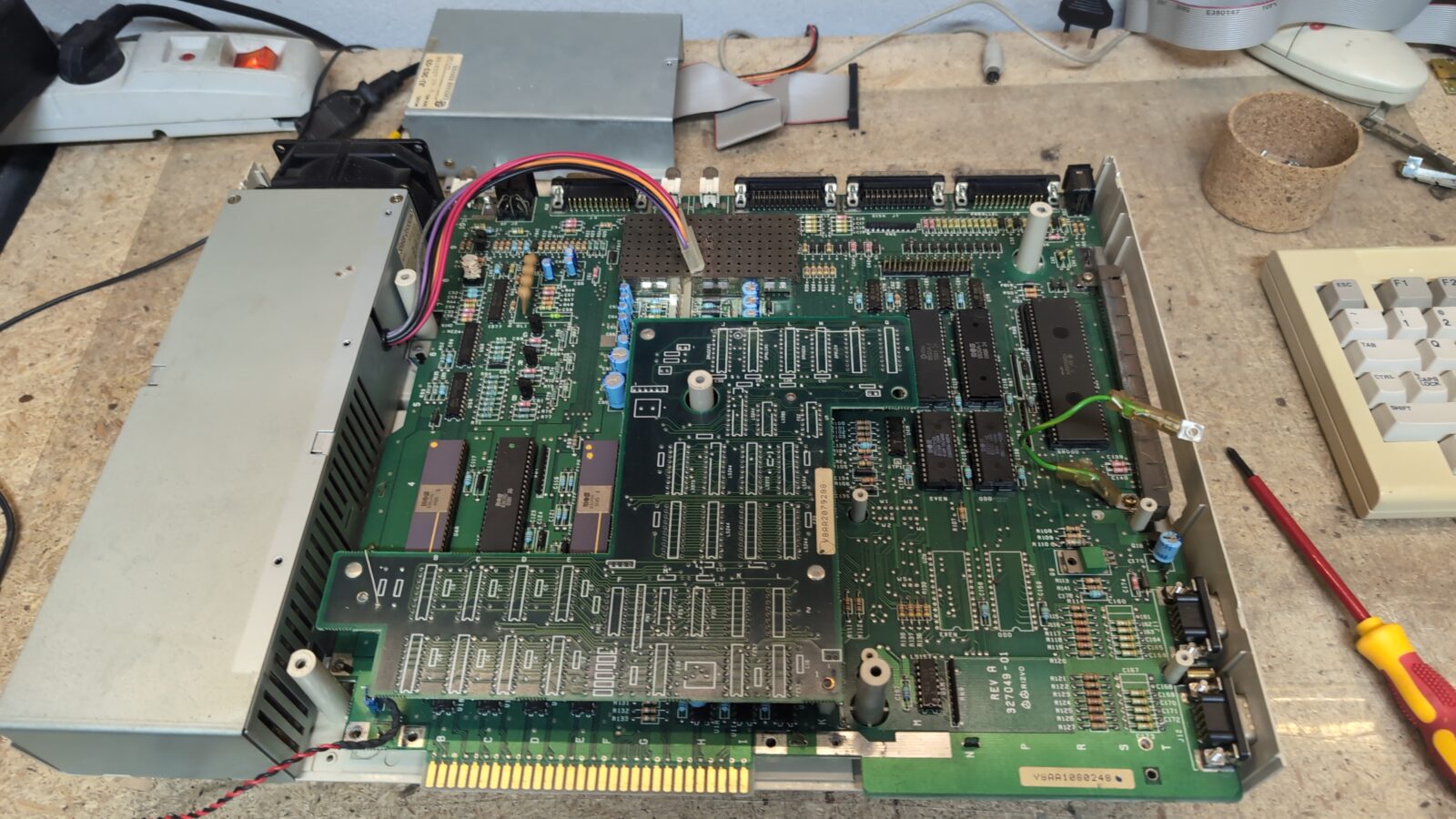
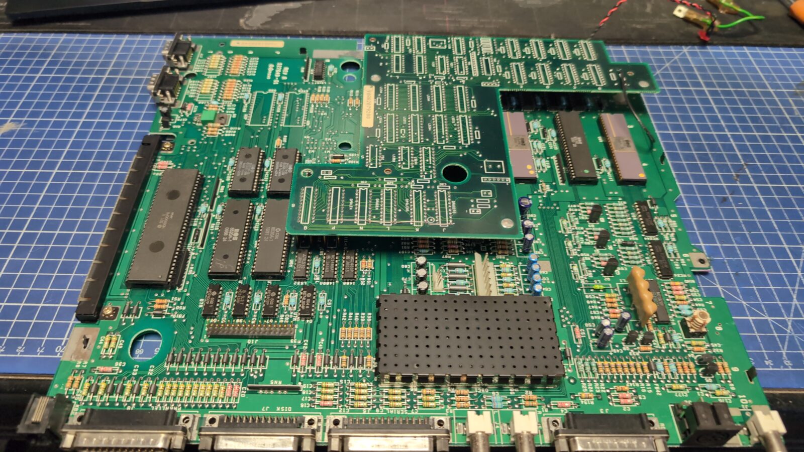
Here is how it looked when I started working with it.
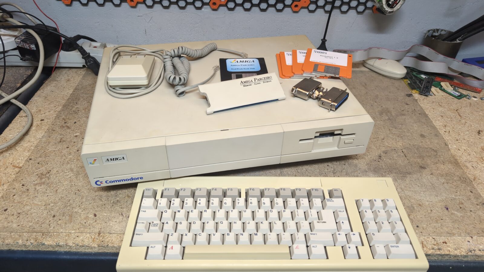
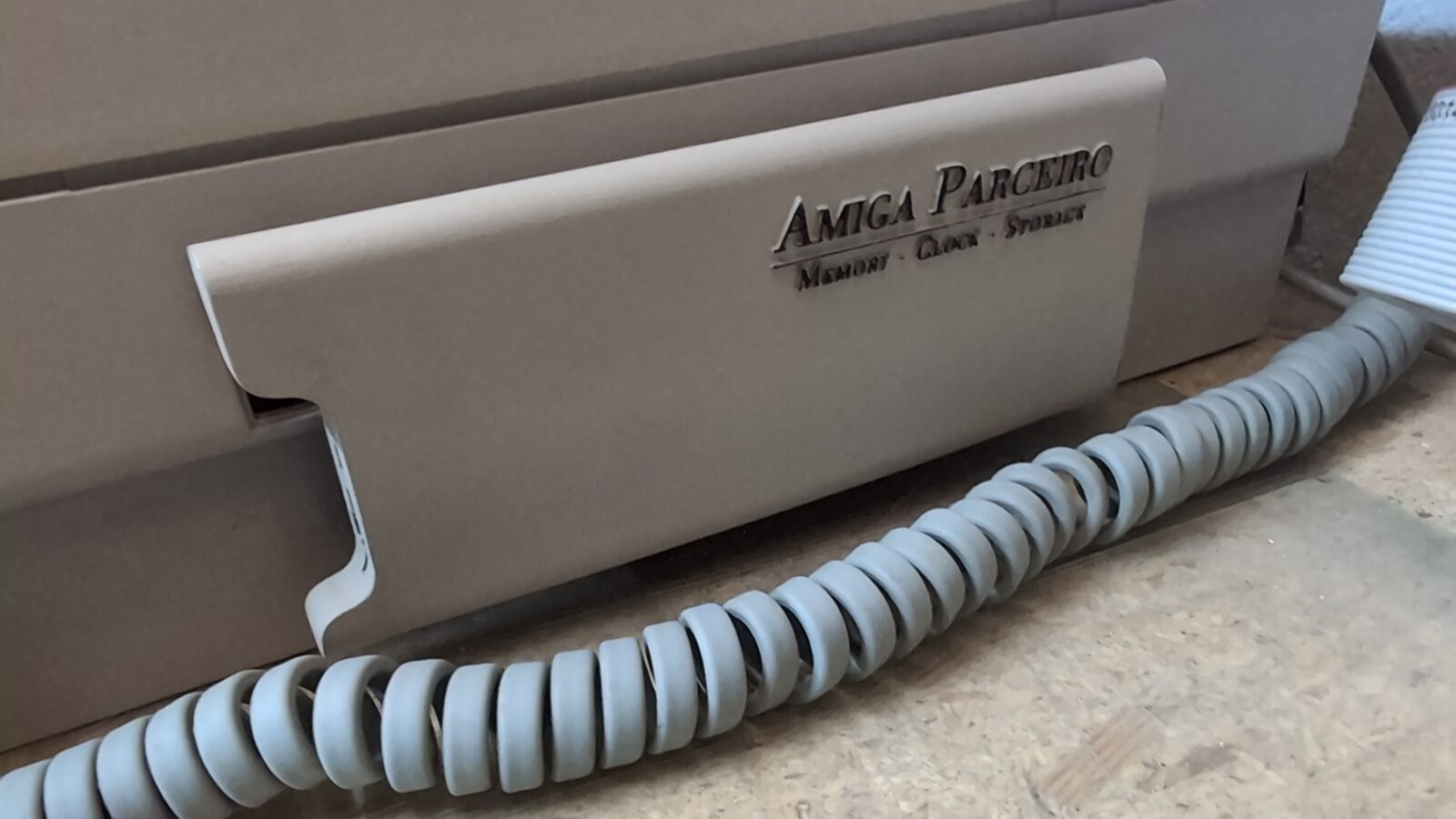
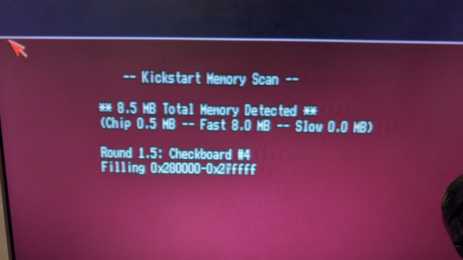
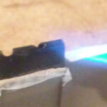
Before further dissection, I had to try it over a composite with the Parceirio plugged in 🙂
The job
Next, I moved on to further disassembly and started working on a PSU. Standard PSU re-cap, plus, I had to replace the original fan as it was loud as hell. This turned out to be a bad idea, as the original fan is powered straight from the mains, meaning it is a 230VAC fan, so the new fan (although nice) was still loud as hell 😀
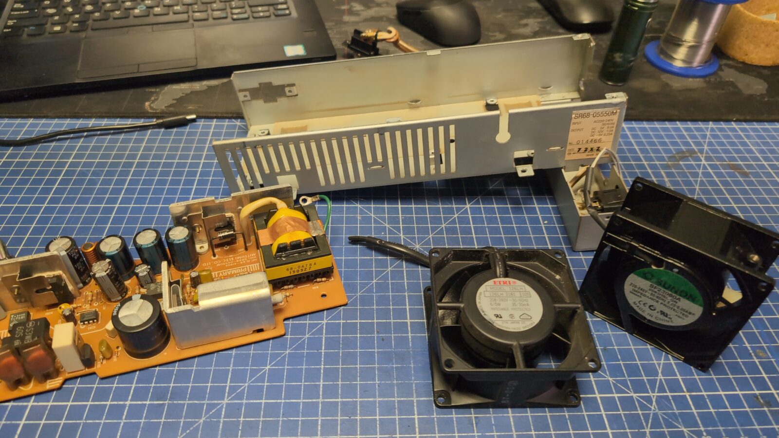
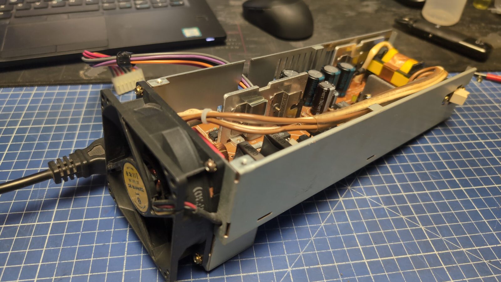
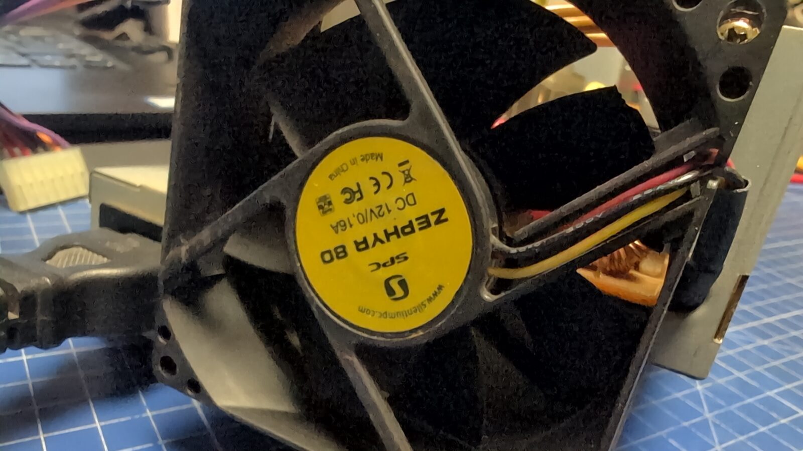
After a bit of tinkering, I’ve replaced the original fan with a standard 12VDC fan that is commonly found in PC PSUs. That was a jackpot if it is about noise reduction.
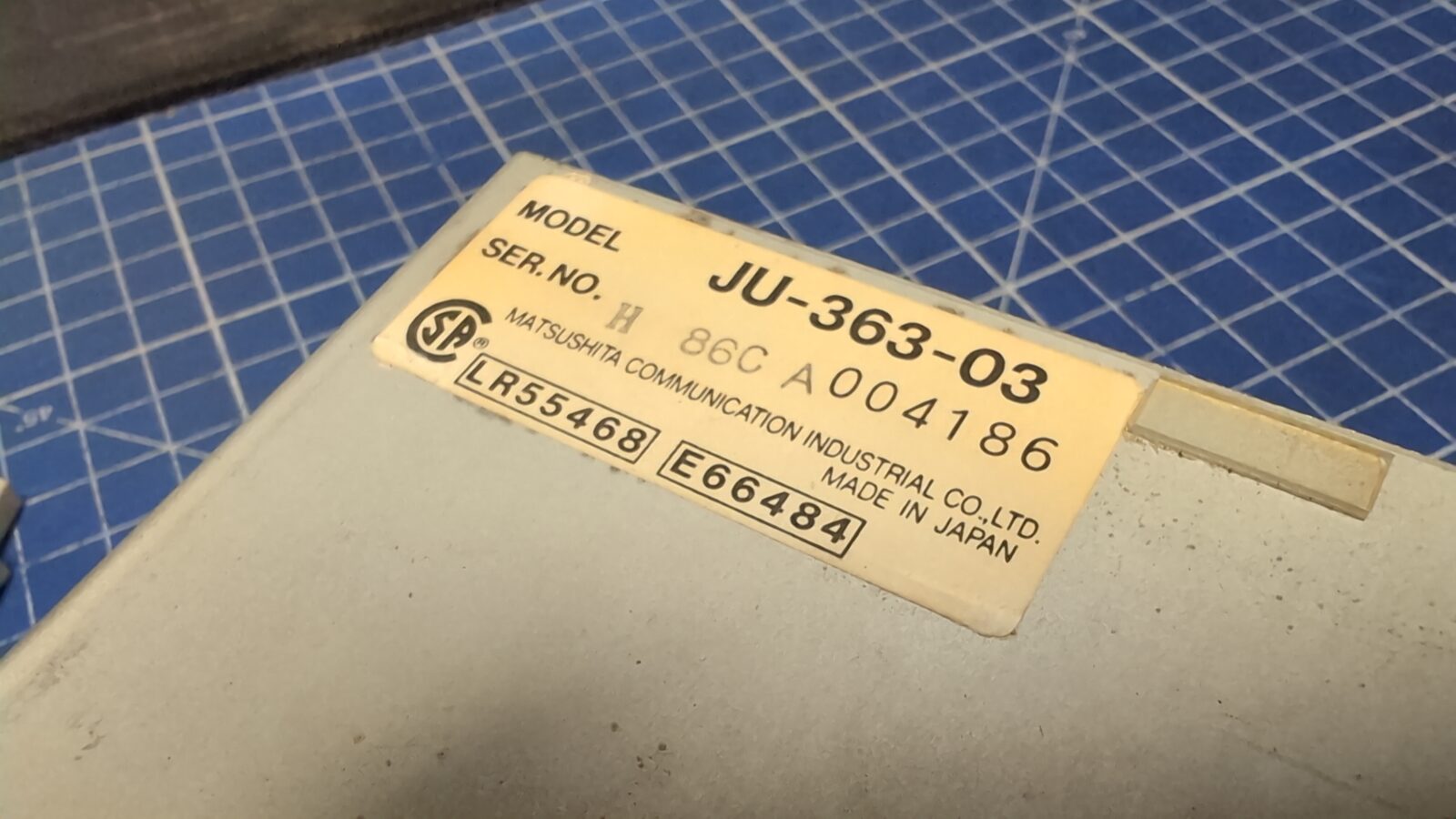
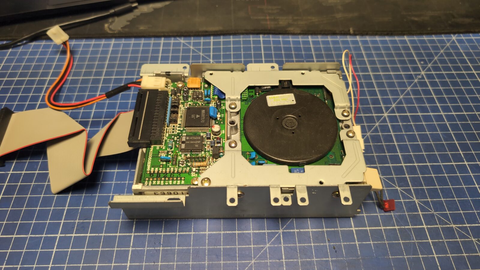
Next, I’ve serviced the 3.5″ floppy drive. Again, a re-cap, cleaning, and lubricating did the job. I’ve skipped the pics and description as it was shown on my blog so many times. I am putting some pics of the drive for future reference.
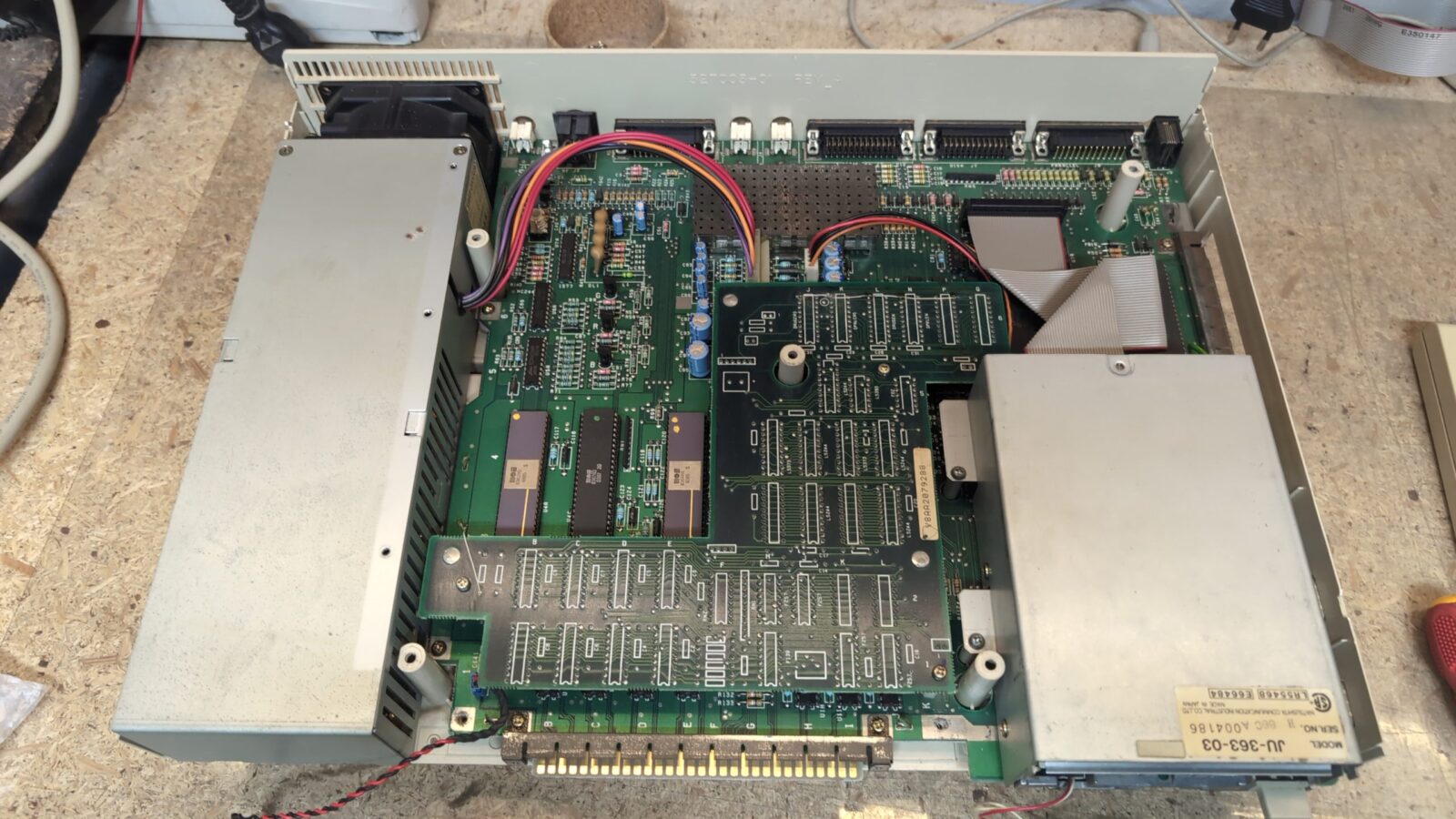
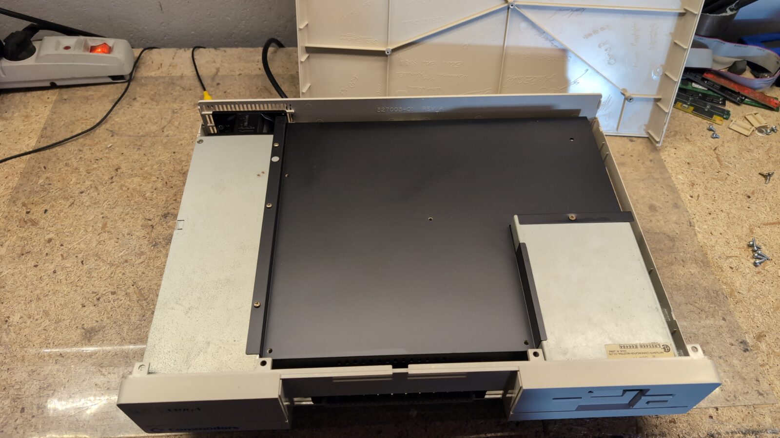
The PCB
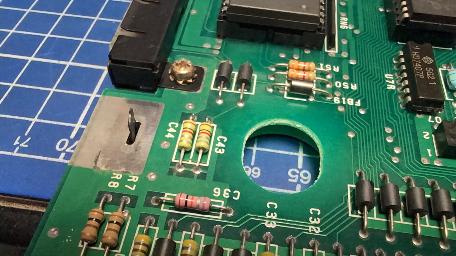
The plan for the PCB was rather simple. Re-cap, ports cleaning, replacing some ugly soldering, and bringing back the original video that was changed by cutting two capacitors, as seen in the pics.
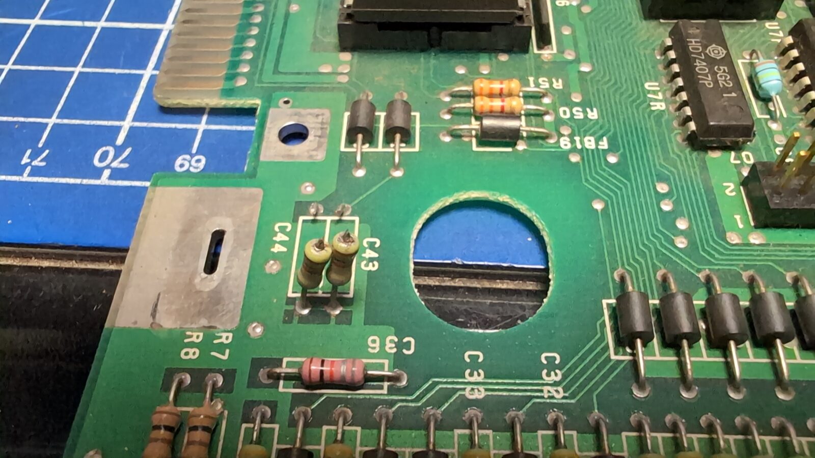
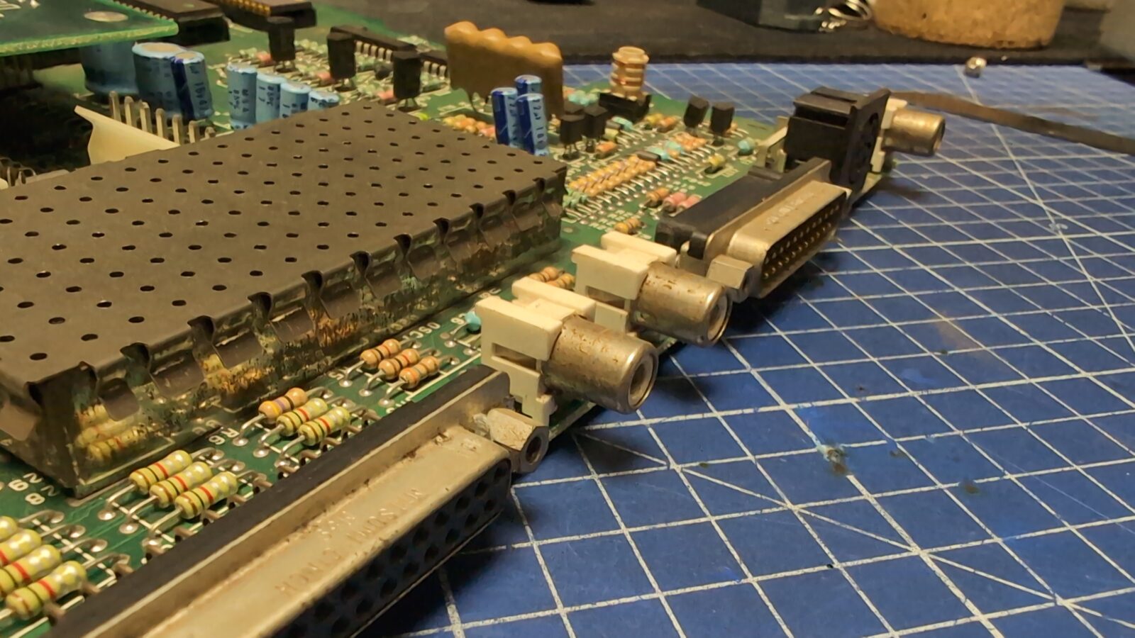
That was all fixed, along with the rusty metal parts, which were cleaned and painted.
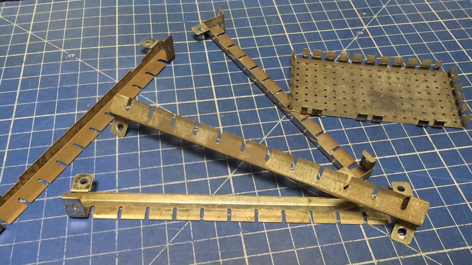
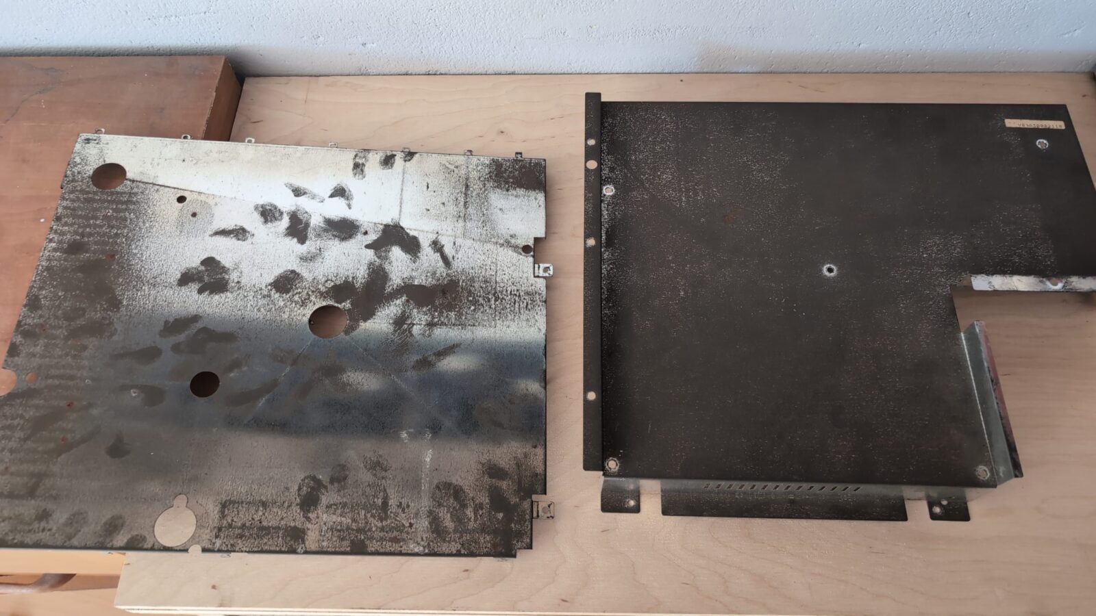
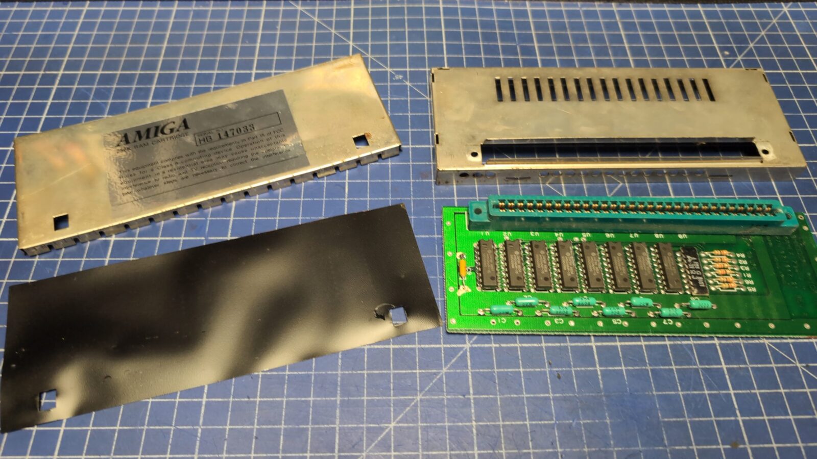
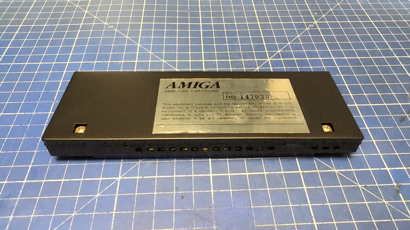
The rest of the metal shielding and the RAM module also underwent a similar process.
The keyboard
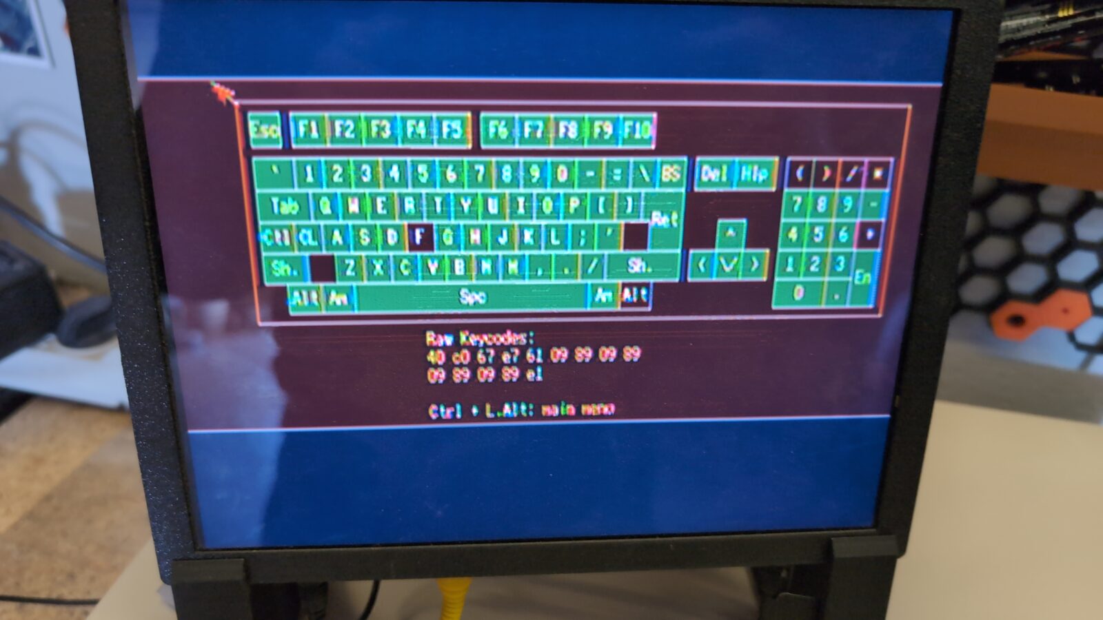
After running some tests, it turned out that the keyboard has some issues that have to be addressed.
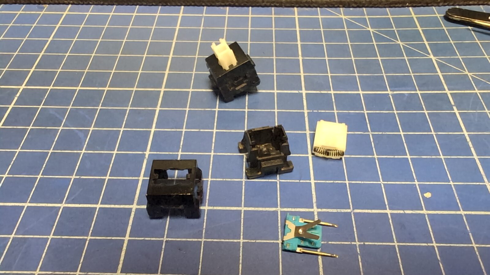
Some keys were simply not working, so they had to be disassembled and cleaned. Rather simple stuff.
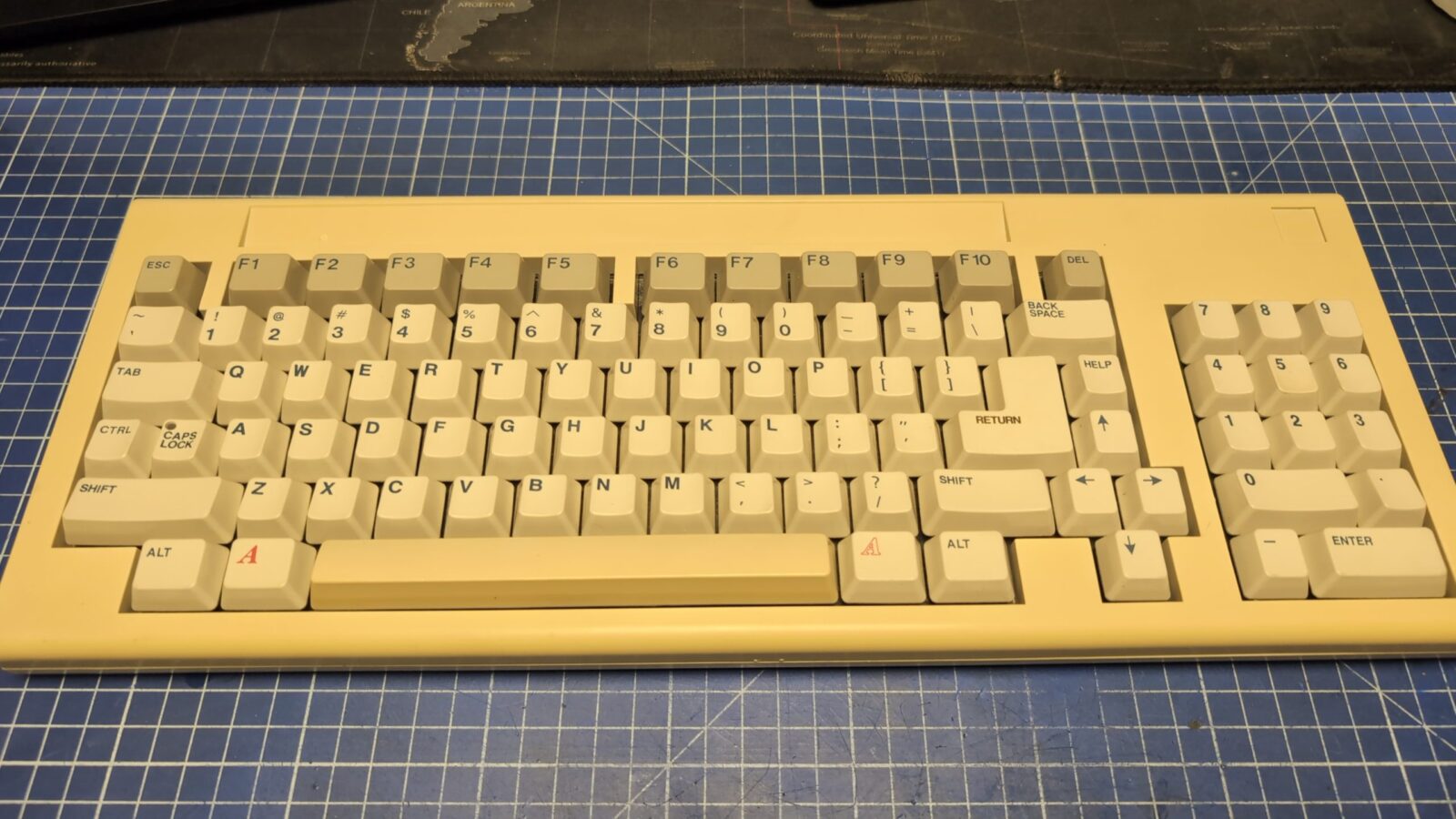
The pic was taken before retro0brighting.
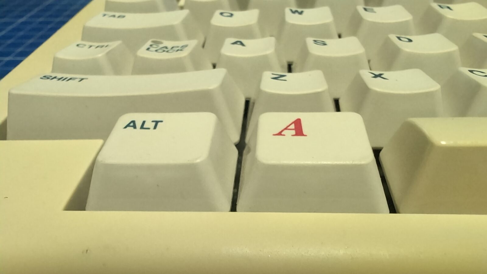
The famous red AMIGA key 😀
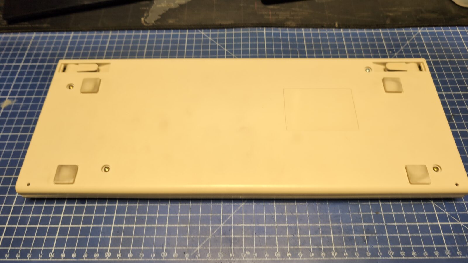
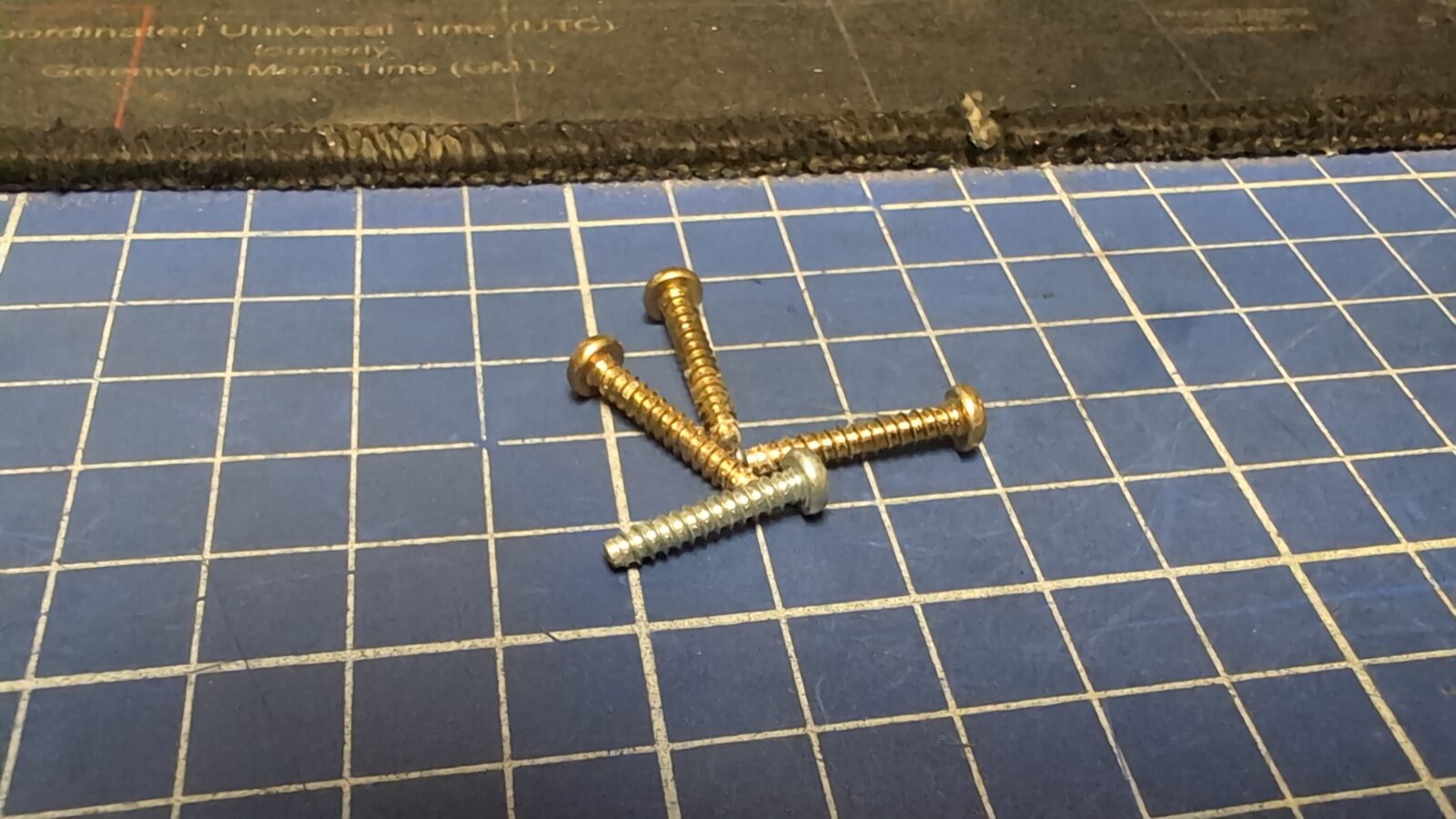
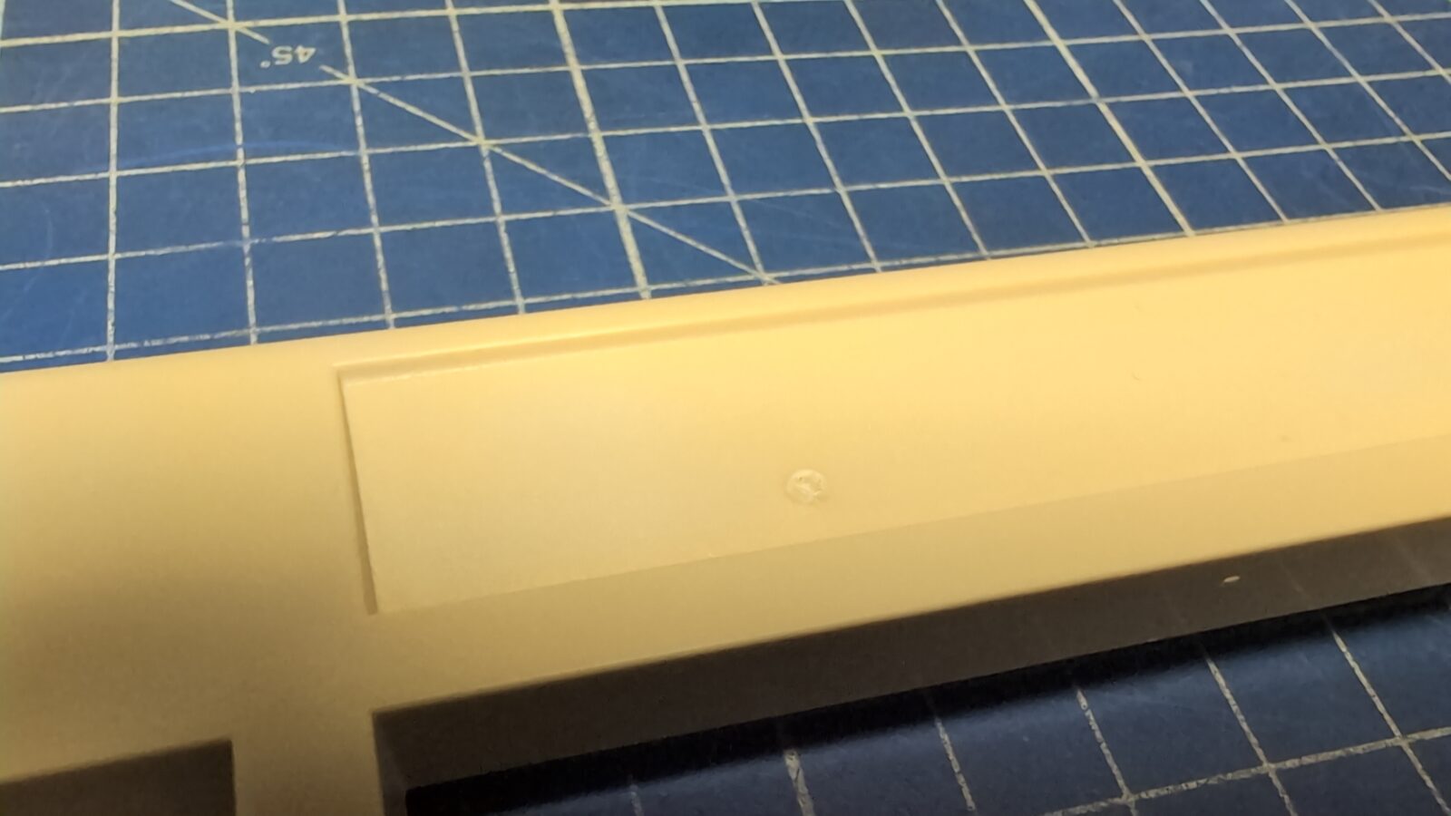
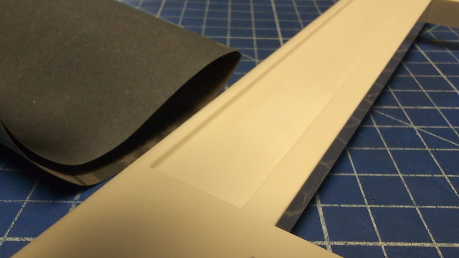
The next issue was a problem with a screw. Someone used a long screw in the wrong spot, resulting in a bulge on the top cover of the case. This looked bad, so I had to address it. First, I’ve used a heat gun to shrink the bulge, and after this, a bit of sanding made the problem invisible again 😀
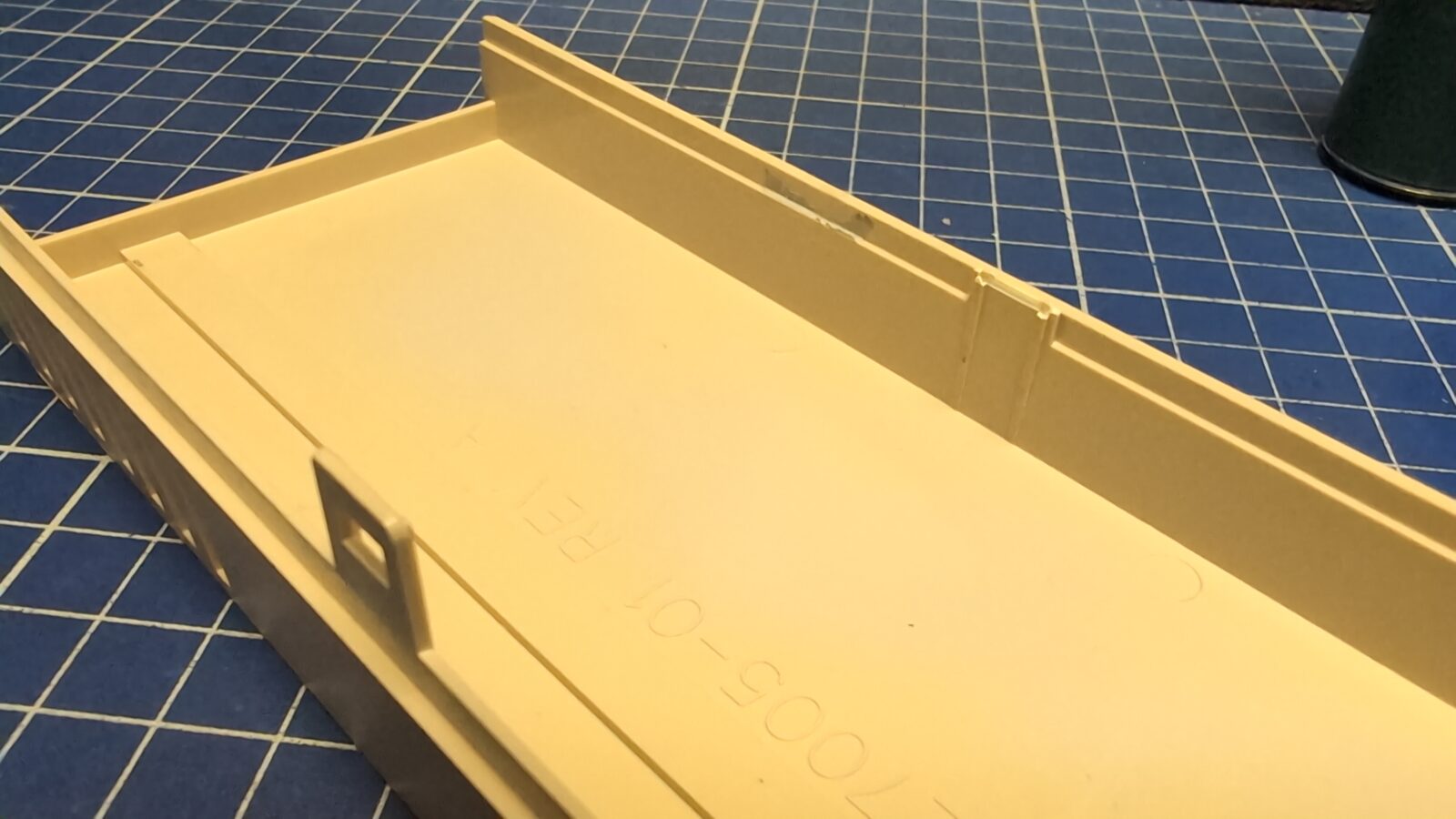
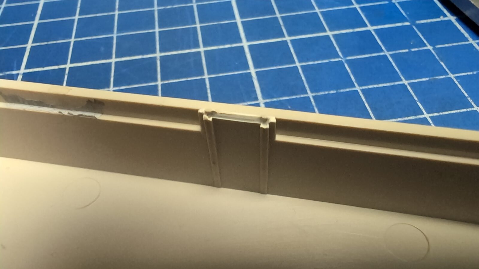
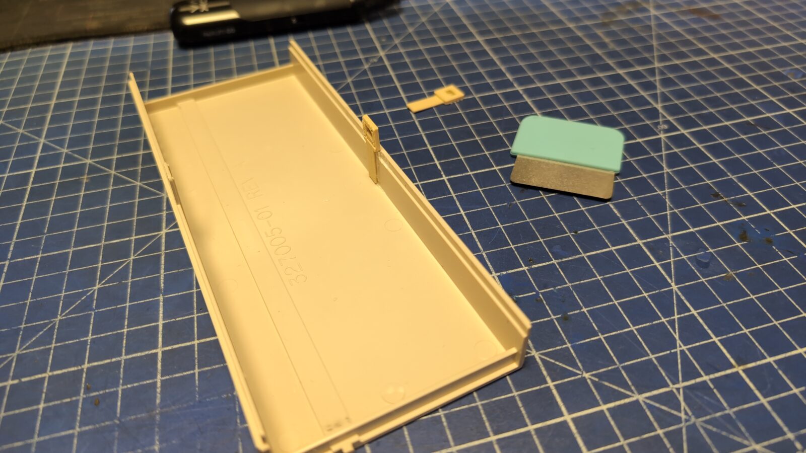
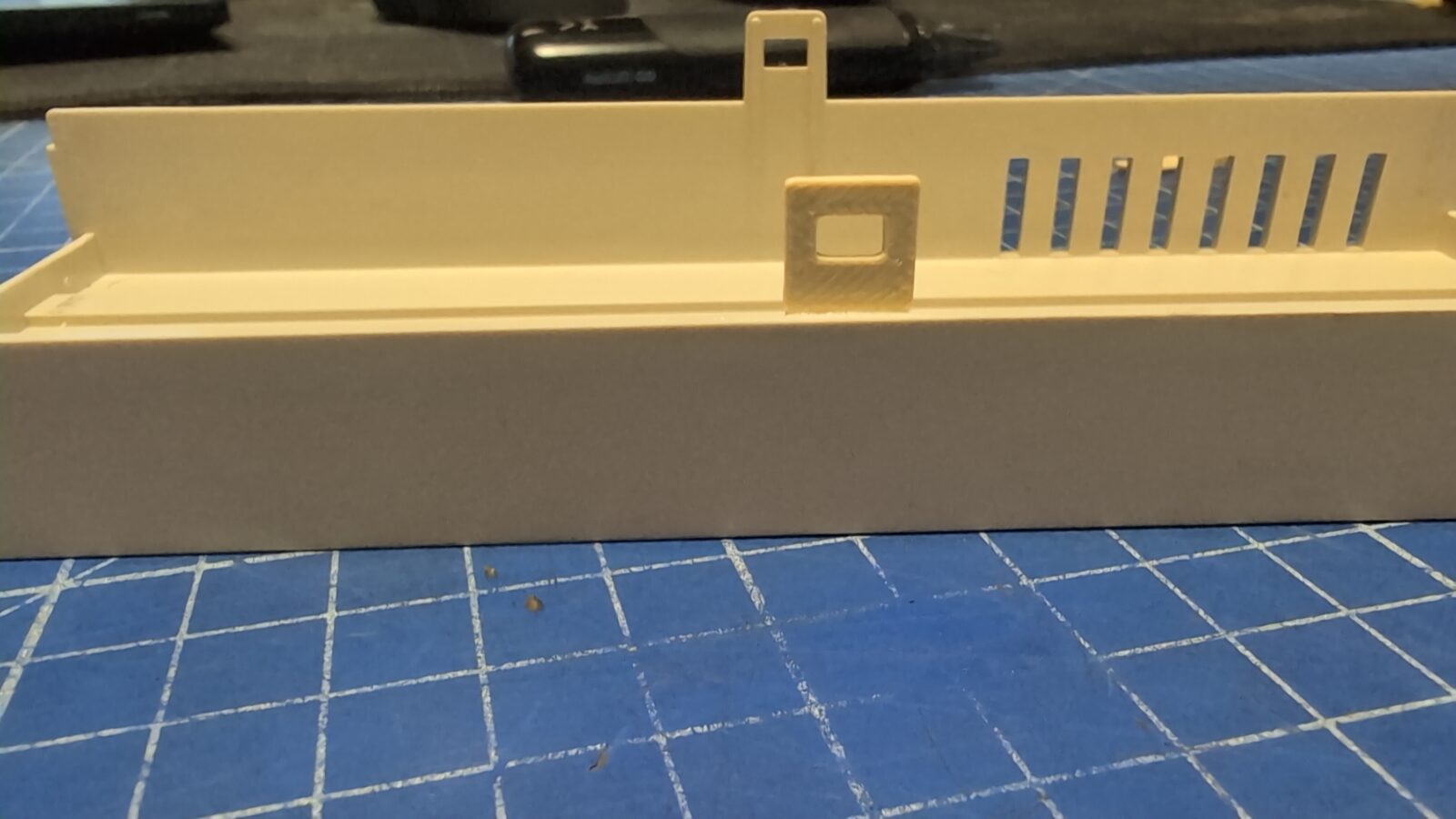
Lastly, I had to address the broken plastic hook of the front panel cover. That was easily achieved by modeling and 3D printing.
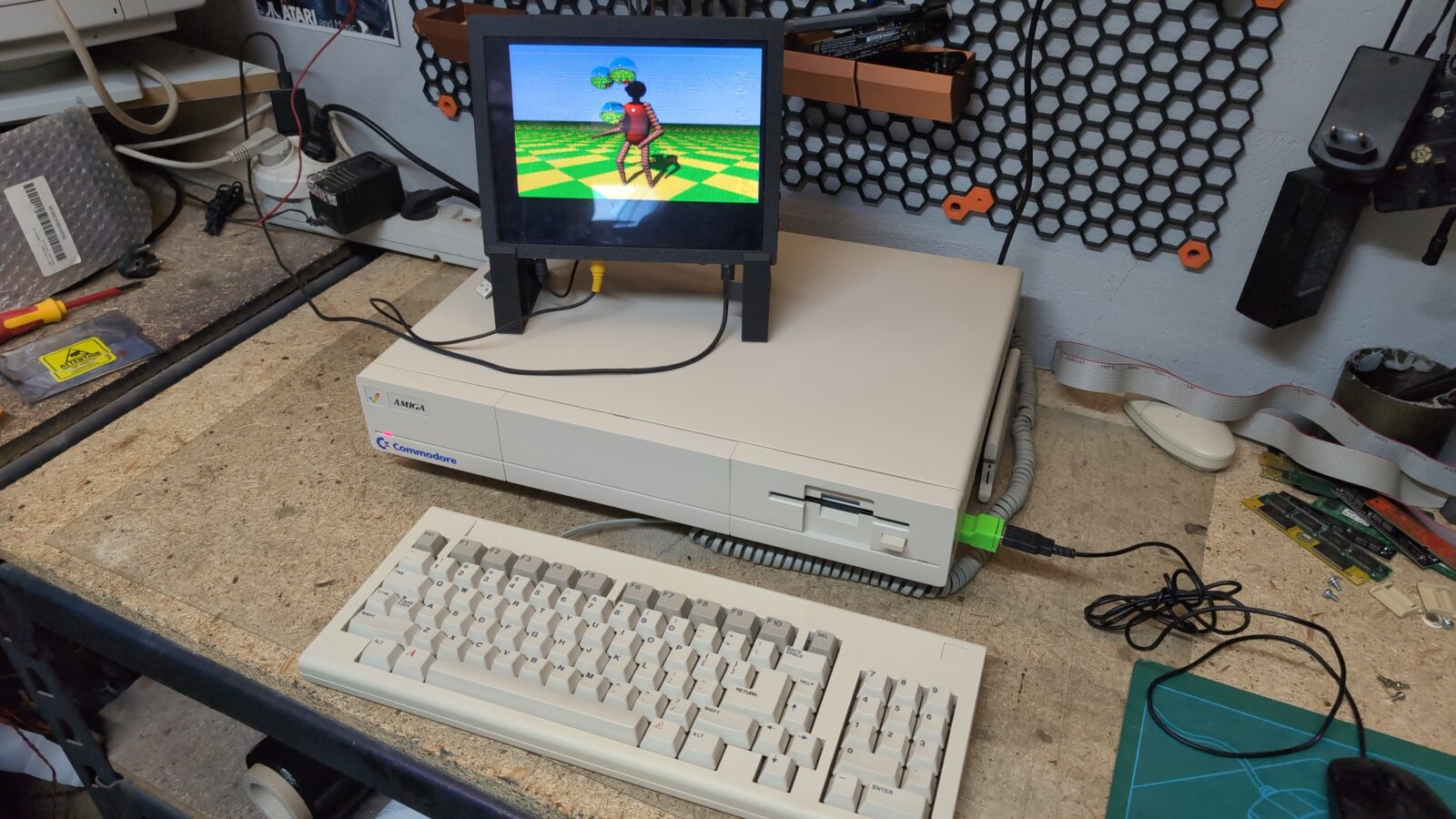
The final pics
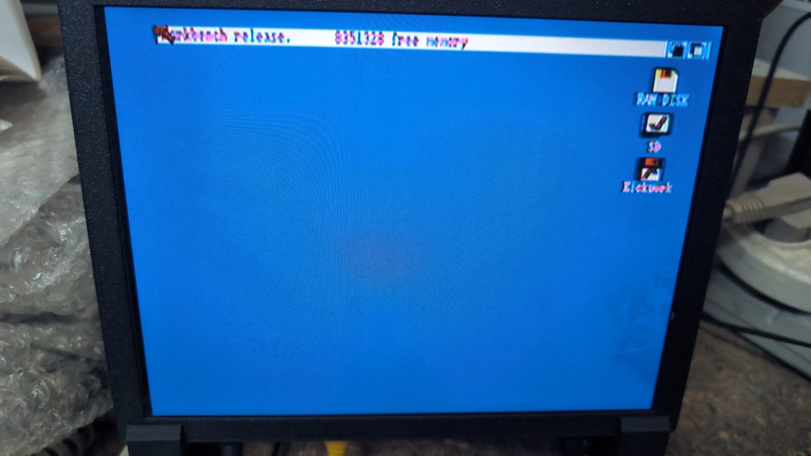
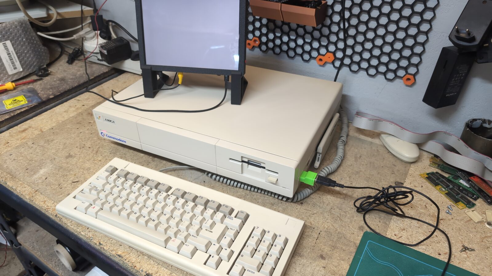
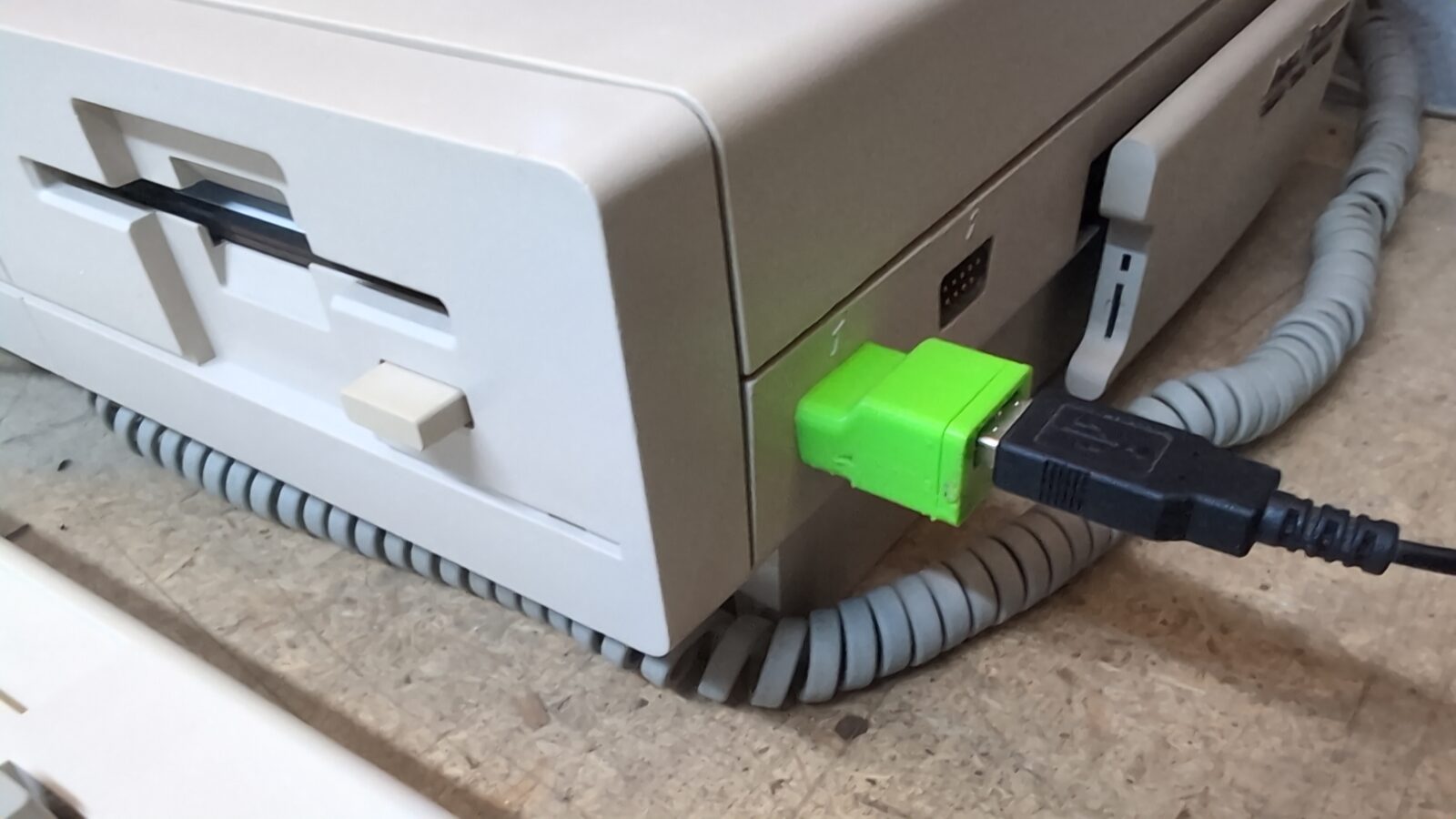
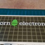
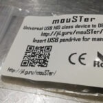
With the Parceiro (which is an awesome upgrade) and the mouSTer connected, the whole setup works like a charm! Ready to play! Plus, the scroll wheel works nowadays too 🙂
The end
Don’t forget to subscribe to the blog (newsletter) to get notified about new blog posts 🙂
Also, some BIG news is coming soon, so stay vigilant 🙂
See you in the next post 🙂
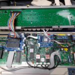
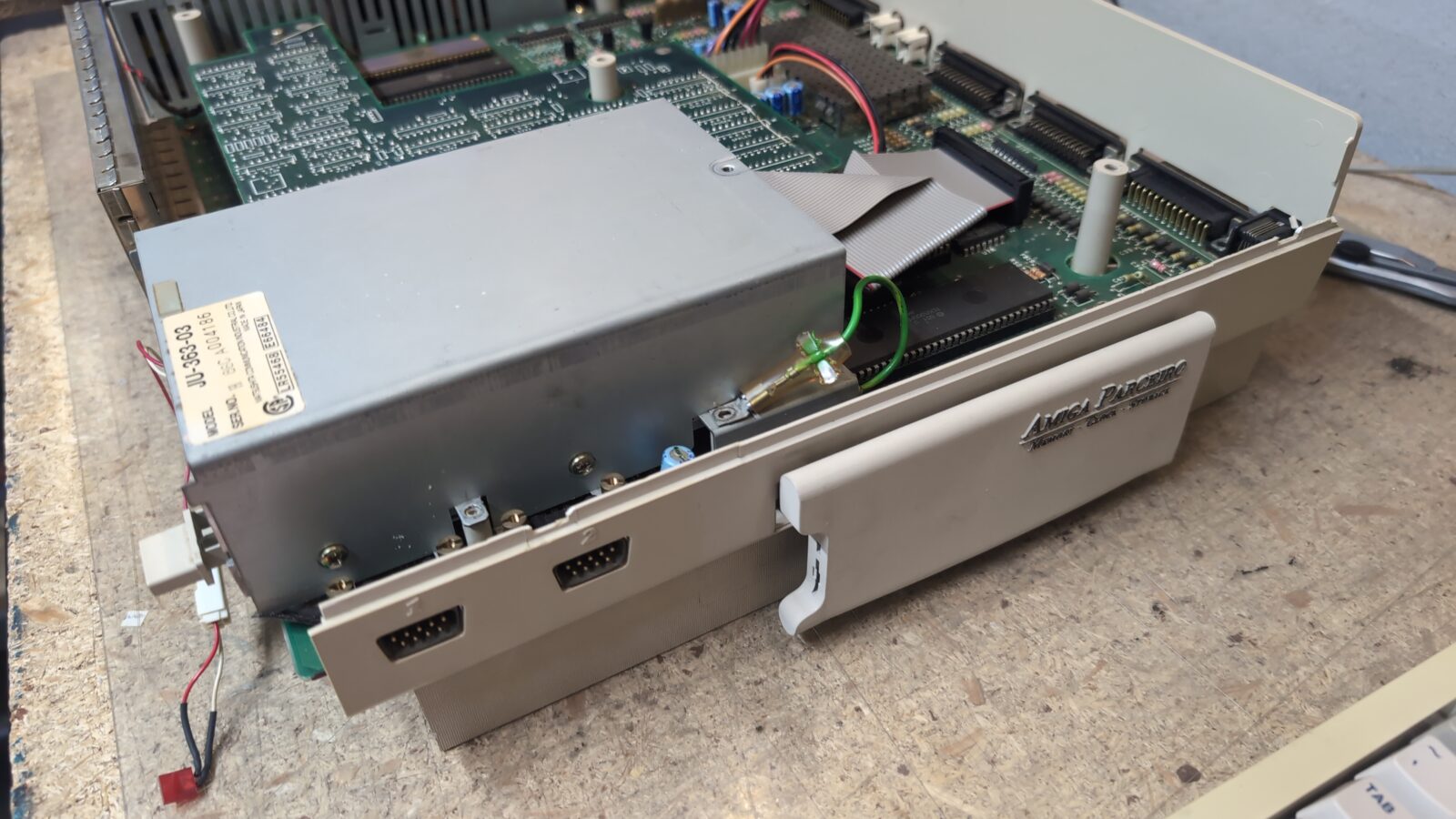
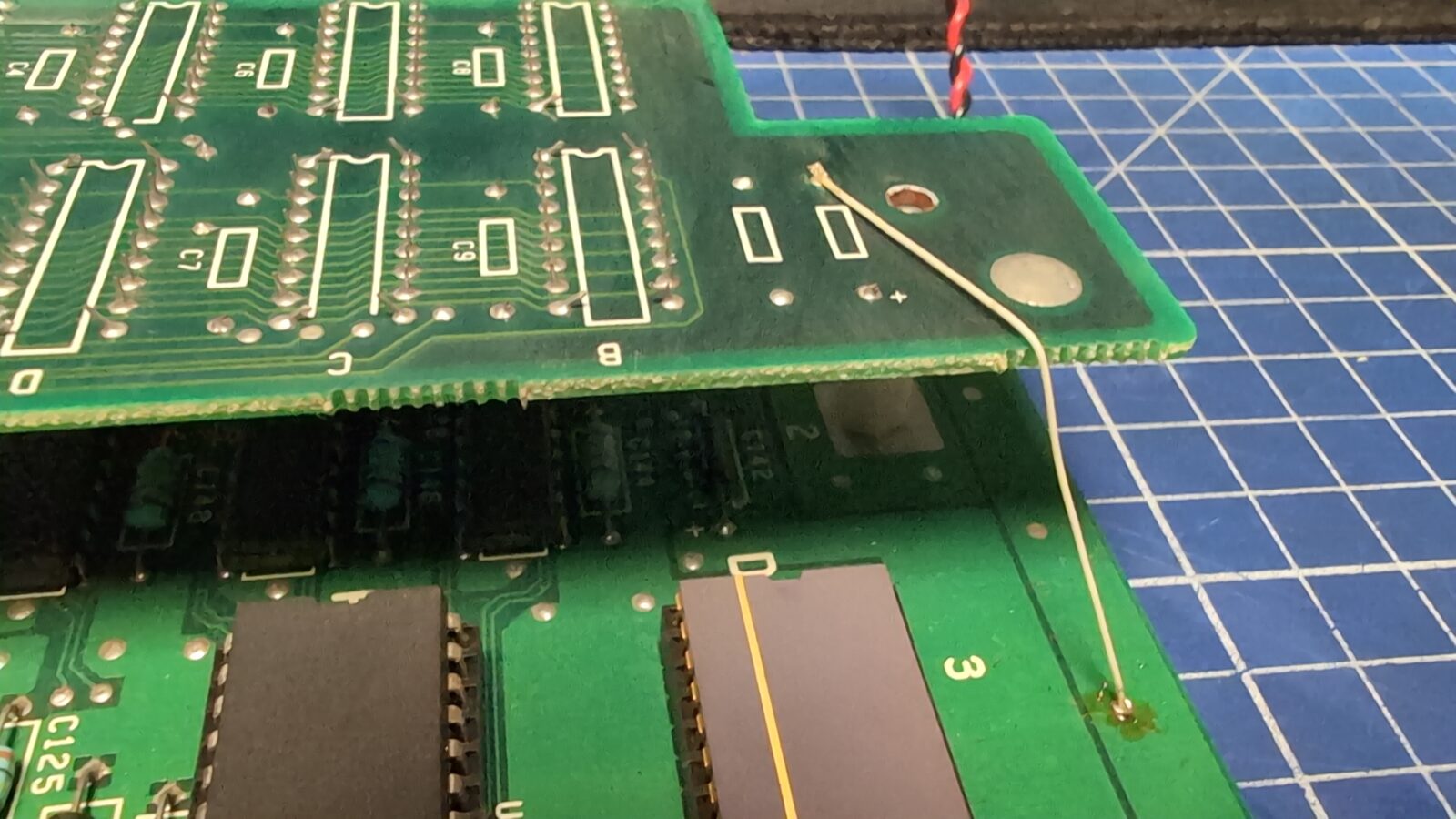
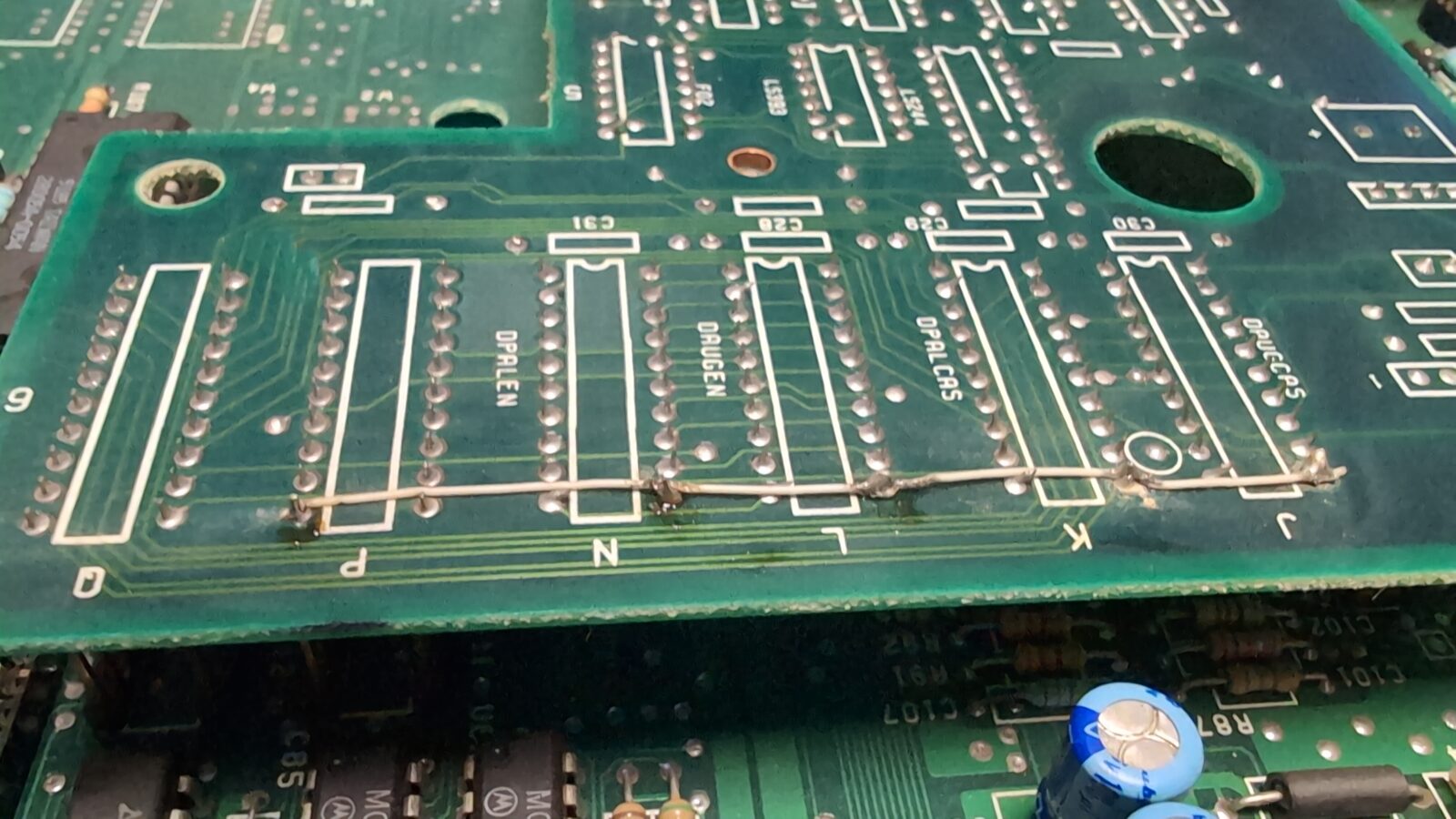
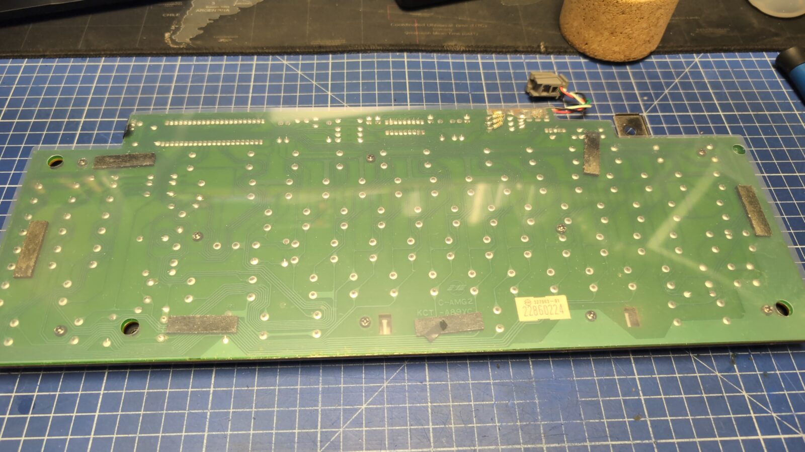
Hi, what are these wires on the daughter board?
Replacement of VSS/VCC, maybe? Did you remove or renew them?
thx
The ones under the chips fix the damaged trace, and the lonely one connects groundplanes. These were deffo done by the previous owner. Yup, I did renew them.
I see, thank you.
Couldn’t see that the trace was damaged. And the groudplane? Is this a common problem? I have a malfunctioning daughterboard. Perhaps I could fix it that way. 🙂
Hard to say if it helps. This original GND plane connection was there already when I disassembled it first, and the Amiga was working nicely all the time. I didn’t run any tests with it removed.
I just added a small jumper and connector to make it more convenient when removing the daughterboard. If it helps, it would be only for stability, I think.
What kind of issues do you have with that daughterboard? Maybe it is just a matter of tarnished connectors?
My Most loved Amiga model too!
“Some keys were simply not working, so they had to be disassembled and cleaned!” means you had to desolder them all and get rid of the metal plate mask first? Or you can desolder only the non-working ones?
I’ve desoldered only the non-working ones and then disassembled and cleaned 🙂
A1000. Pearl in crown. Awesome restoration work, Sir.
A1000… my forever sweetheart 😉 Good to see another one handled with care and love it deserves!