… or a motherboard from hell
<the other intro>
Again, an announcement. I am slowly running out of badly damaged computers I am open to accepting broken retro computer donations so If you have a broken/rusty/muddy/post-apocalypse/car accident/burned or simply not working retro computer, I am happy to accept it and will attempt to repair it. The best repairs will be covered here.
I know, I know what you want to say – MAKE A VIDEO out of it!!! – Naaaah, I am not a youtube kind of person and I prefer writing about things that I am trying to fix … but who knows … as they say – never say never 😉
Anyway, if you have a broken piece of retro hardware and would like me to repair and cover it on this blog just drop me an email with some details at [email protected] or contact me through the Facebook page.
Also, please leave comments as this is a great feedback tool for me. This helps me to write better content. You can either comment under posts or on my Facebook page here -> https://www.facebook.com/Retrohax.net/
</the other intro>
<std intro>
This is the second part of Wasabi C64 refurbishing. The first part is here.

</std intro>
Motherboard
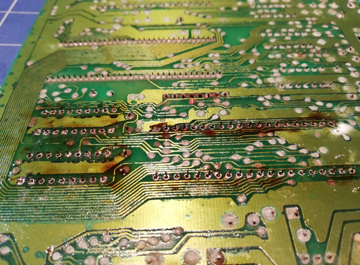
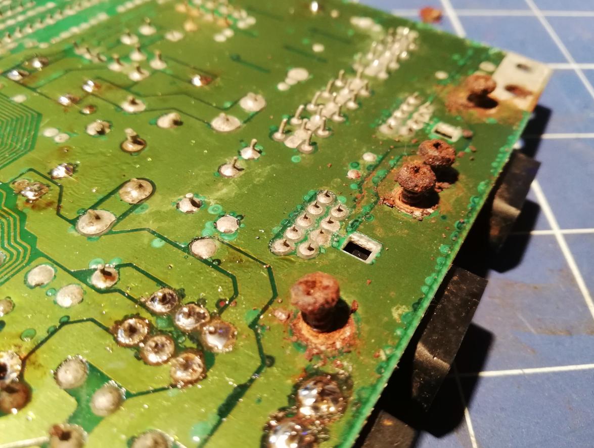
First of all, I had to remove all the dust/gunk/insects, and dirt from the motherboard. I did it with the help of warm water and a brush and after this, I put it into an ultrasonic cleaner for 30 minutes. When it dried, I could start looking for missing components and other damage.
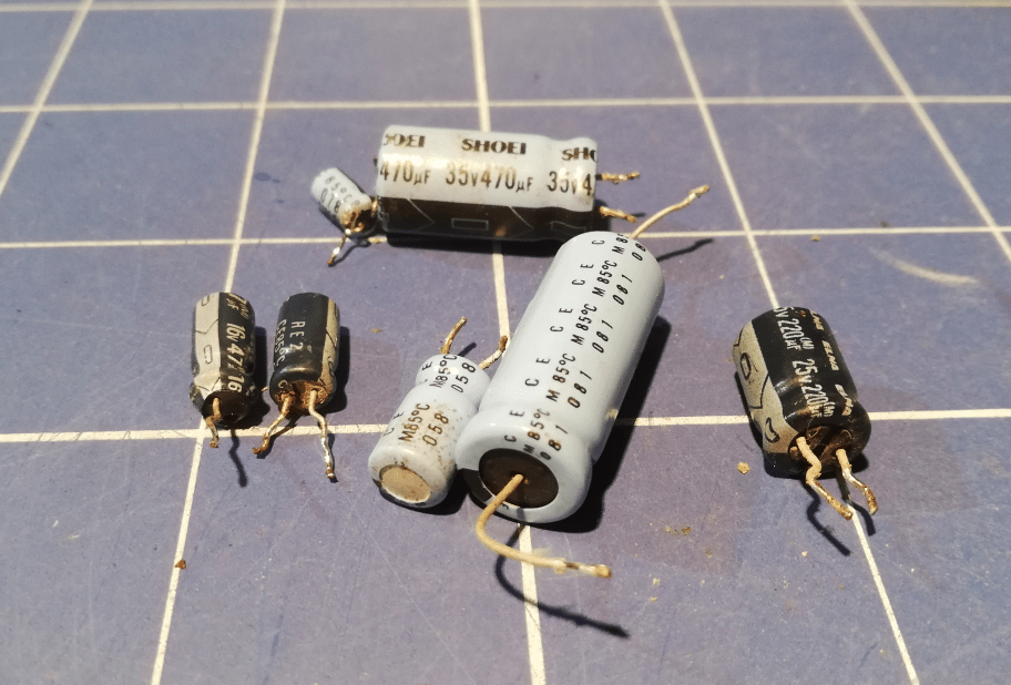
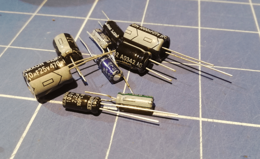
First of all, let me tell you that this is a PCB assy. no. 250469 rev. B motherboard and thankfully at first look, traces weren’t damaged by corrosion but there were missing and bloated capacitors that I wanted to address first. I’ve removed those “better looking” caps too and installed brand new ones.
By the way, we have capacitor replacement KITs for Amiga computers HERE. For now only for Amigas but more KITs for other retro machines will be available soon.
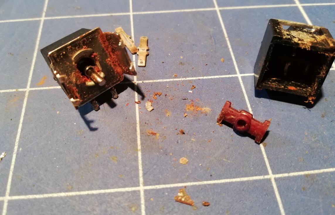
Power switch
Next, I had to address a power switch. This is a common problem with old C64s that were stored in bad conditions. Pins inside tend to tarnish and stop conducting electricity. In such a case, a switch has to be desoldered, disassembled, and cleaned, which is what I did 🙂
Chips
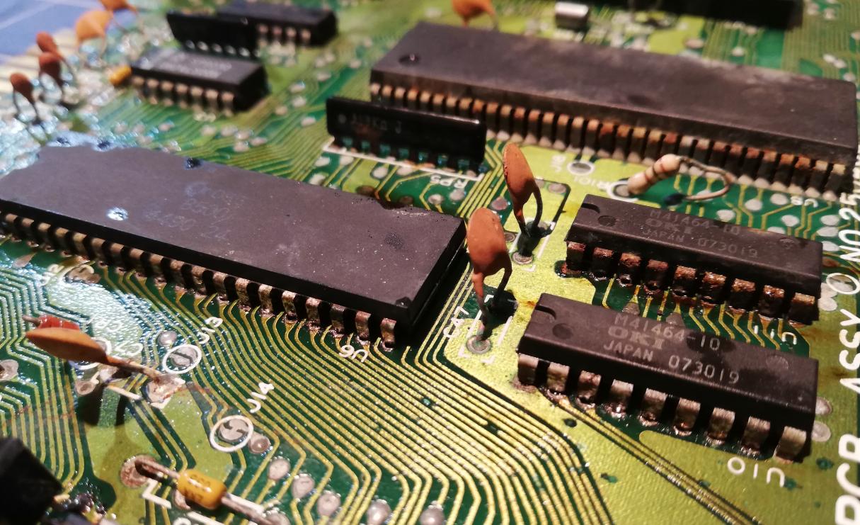
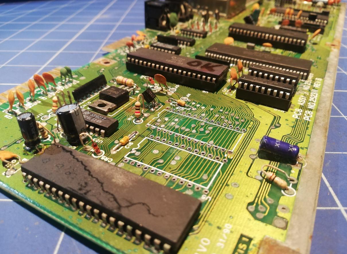
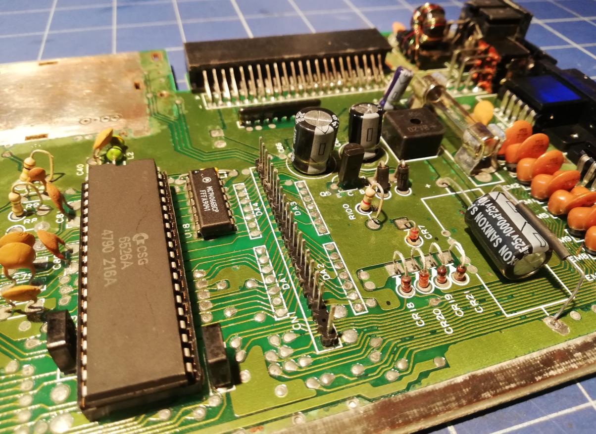
With a cleaned and working power switch and caps in place I run a quick test to check which chips are fried.
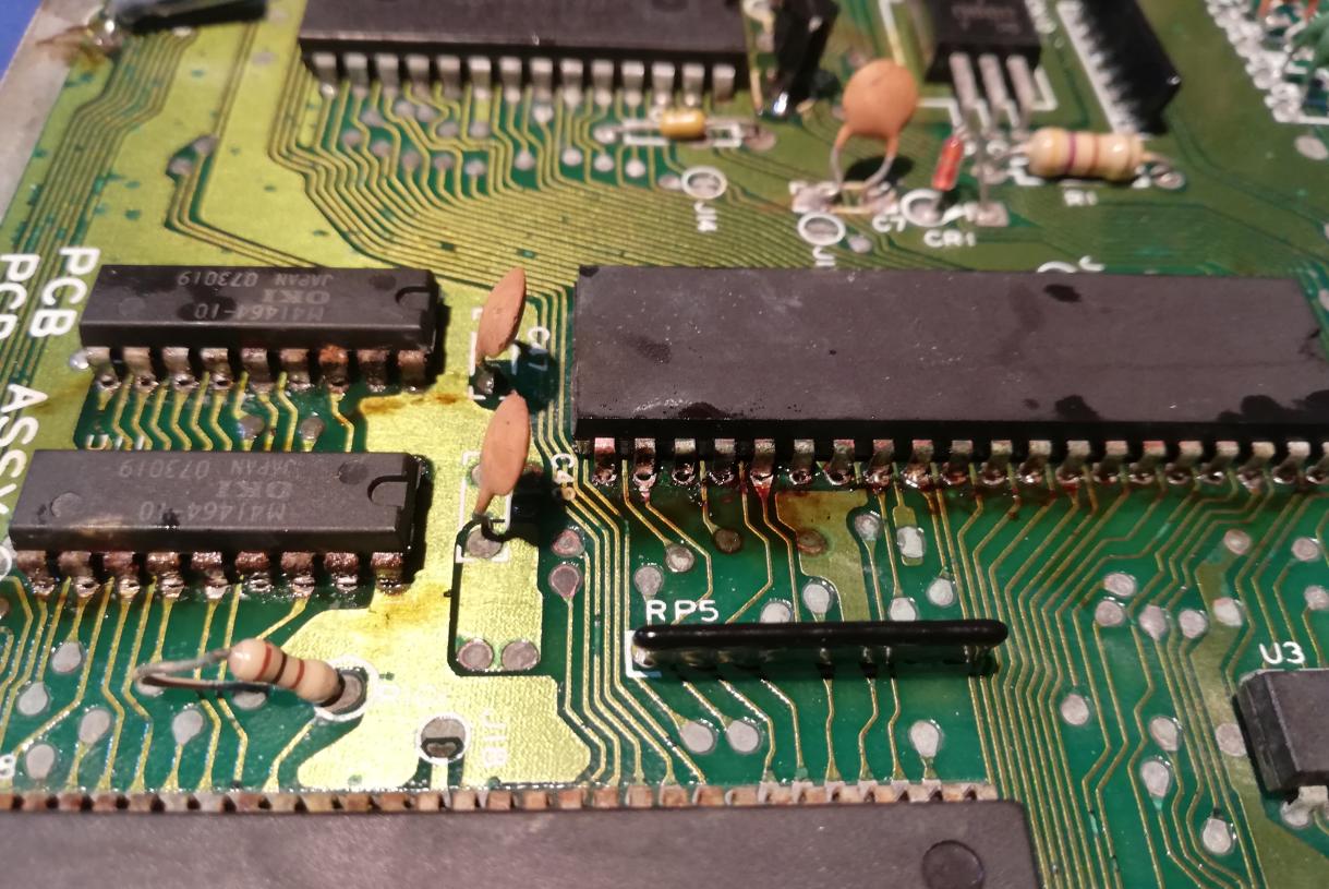
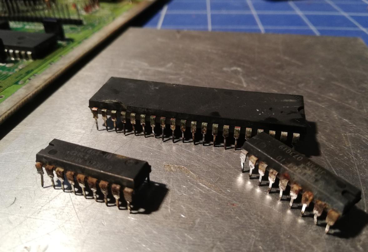
My preferred method of looking for faulty ICs is to supply power and check if any of them is getting hot by simply touching them with a finger. I’ve quickly found that MOS 8500 (CPU) and both RAM ICs are shorted as all three ICs (1xCPU and 2×41464) were quickly getting hot. This kind of fault suggests that a bad power supply was used to power on C64 because supplying more than 5VDC on a 5V rail will damage these ICs first most of the time.
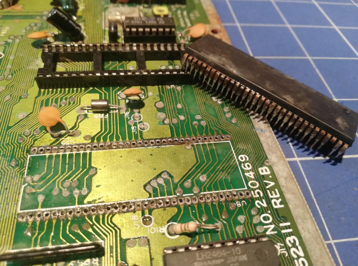
Fortunately, I had a few spare parts so I could continue with desoldering and installing sockets. This is not an easy task because the simple desoldering gun will not suffice. I also had to use desoldering wick and tons of flux. This is all due to the oxidation of the original solder. Reaction with Oxygene created a sort of crust on all solder points.
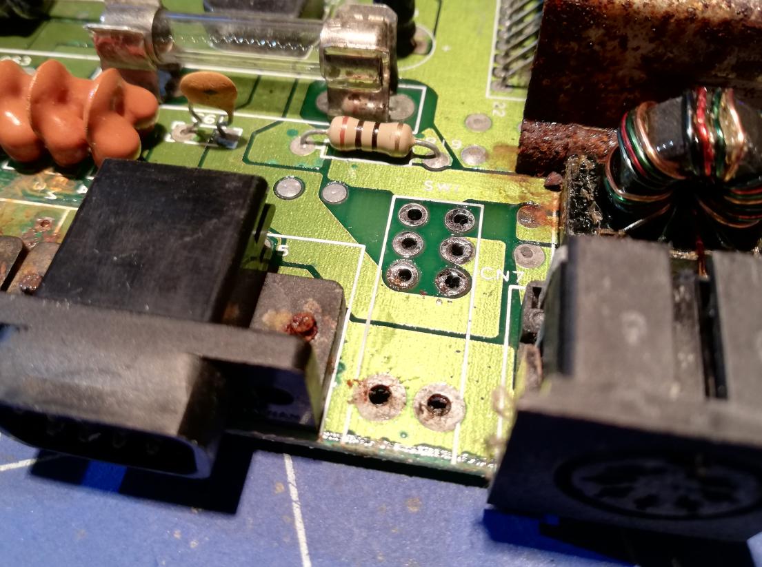
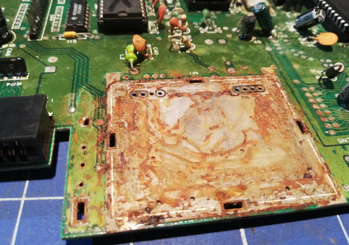
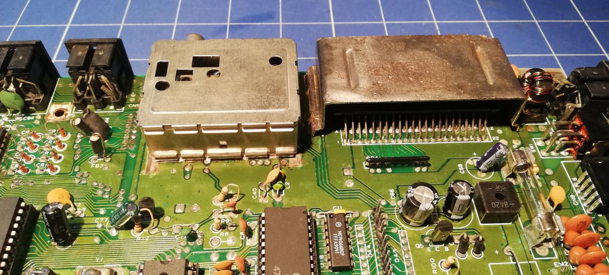
RF modulator
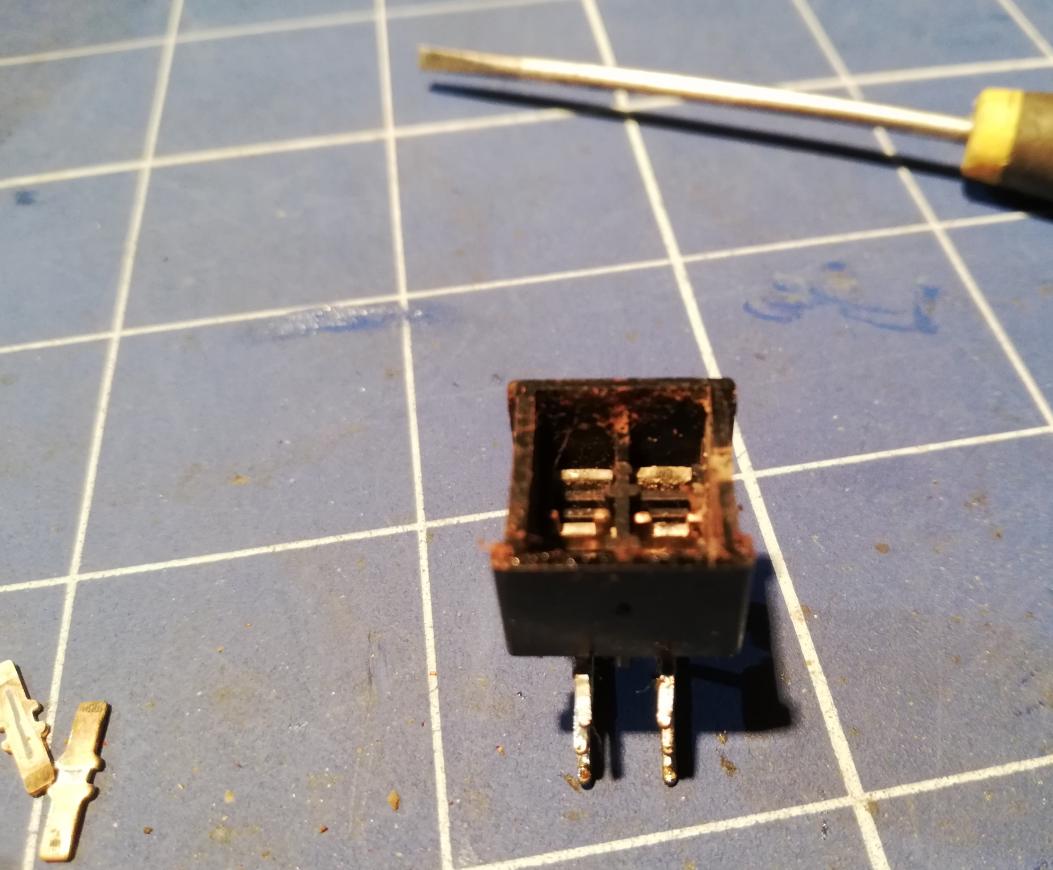
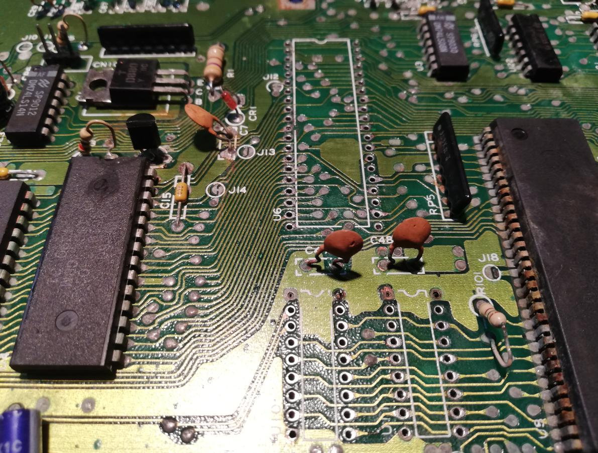
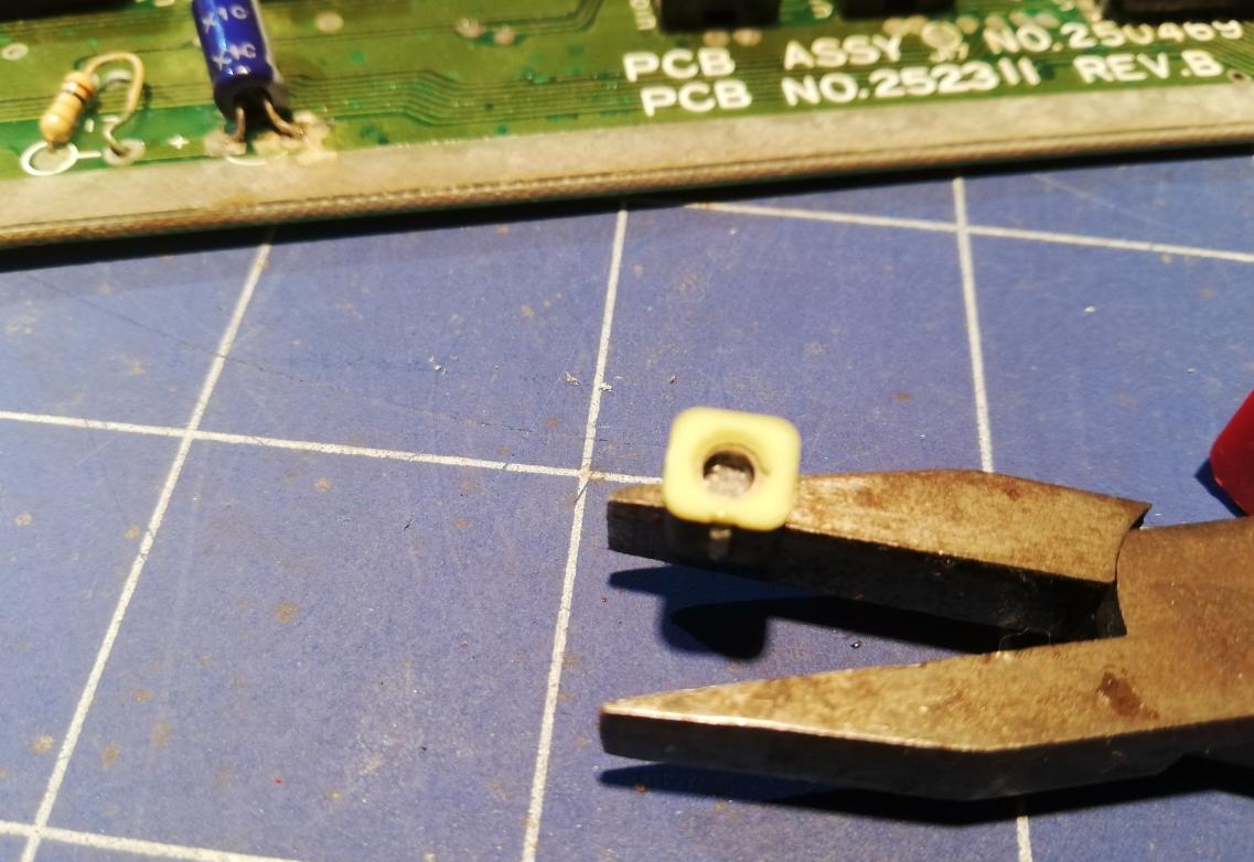
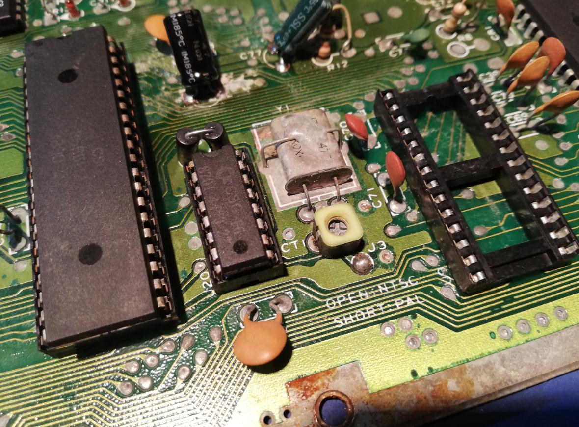
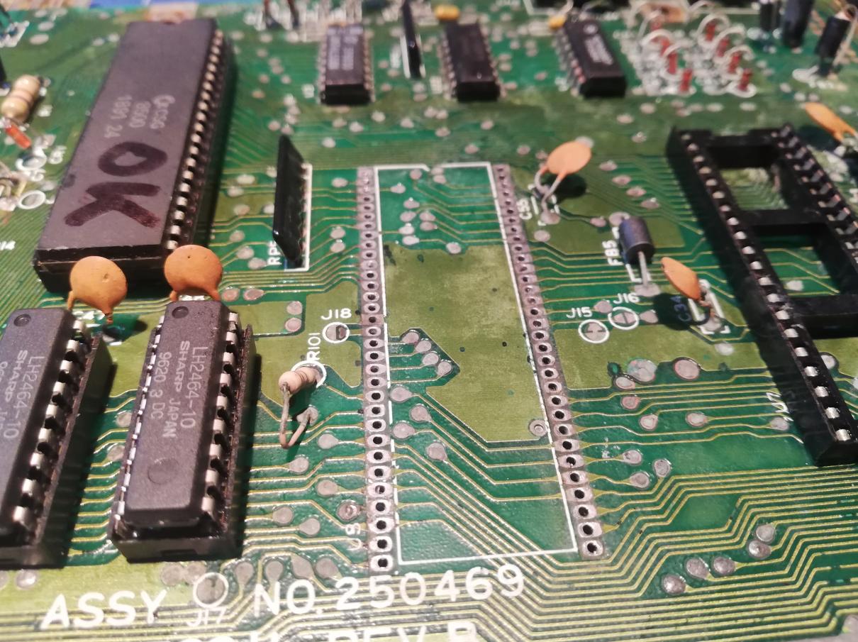
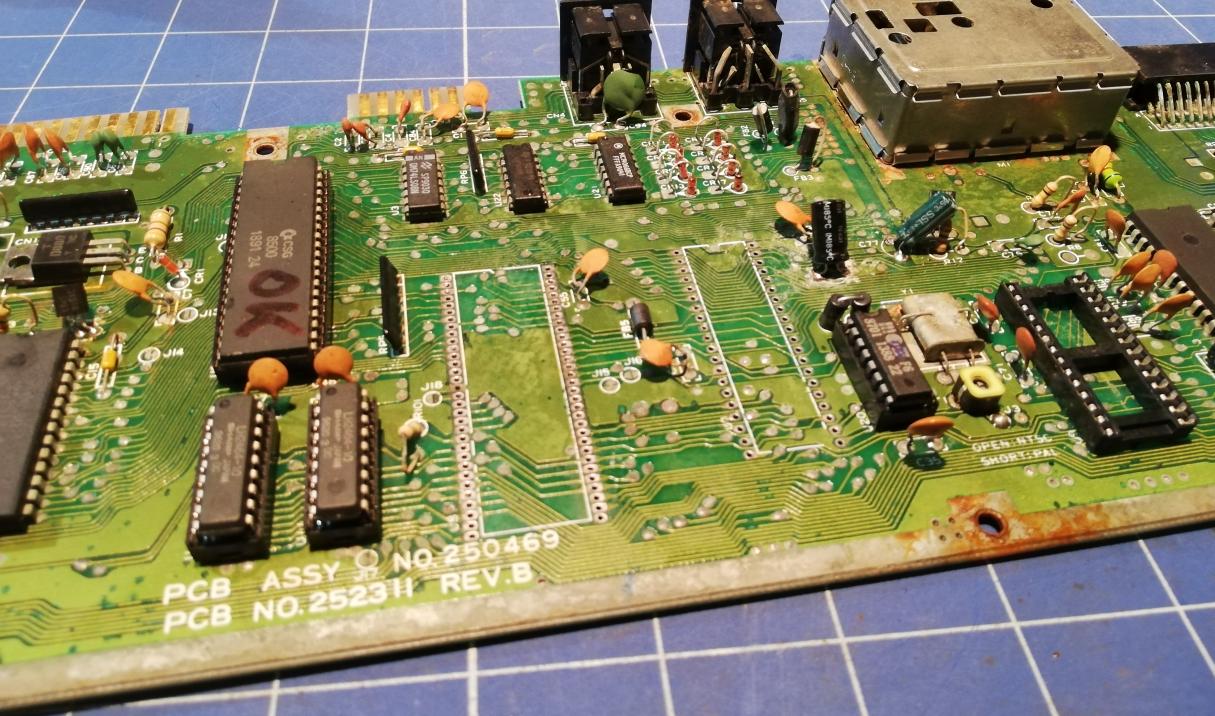
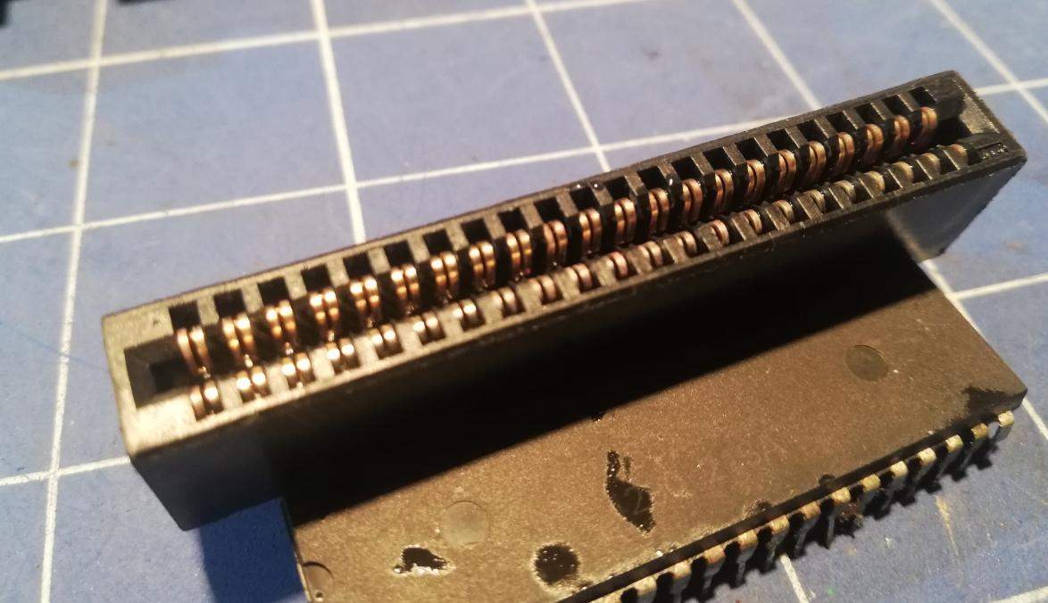
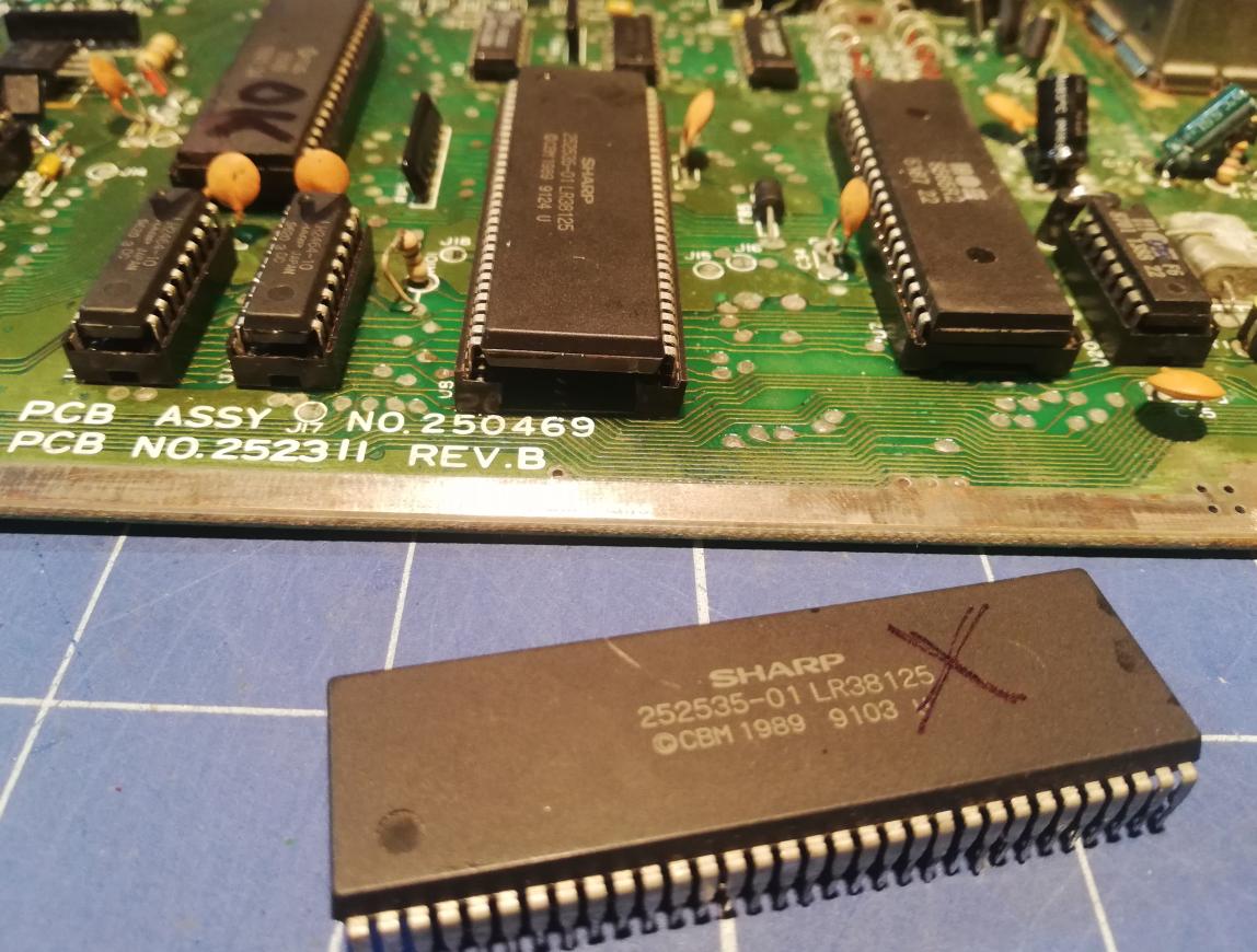
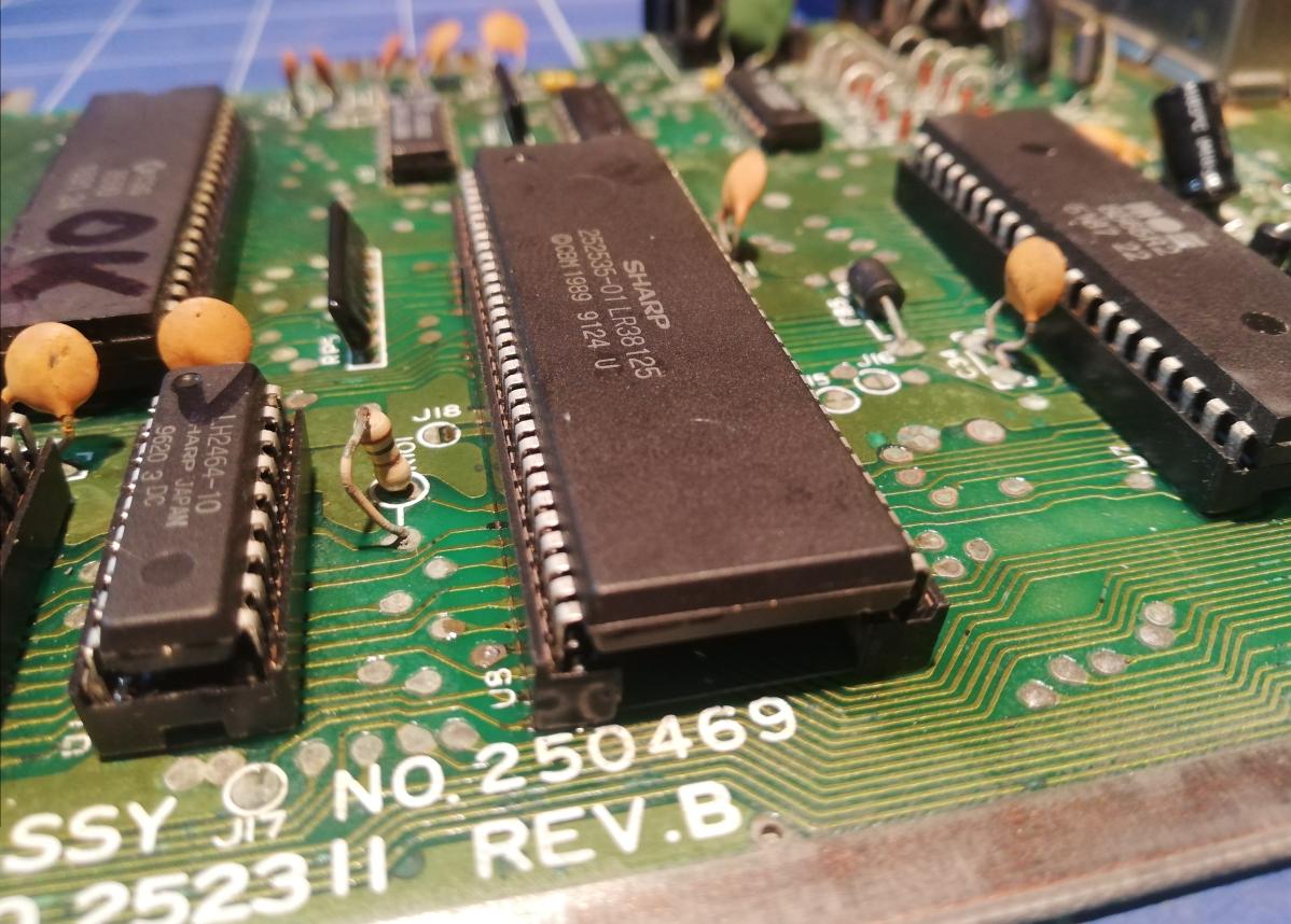
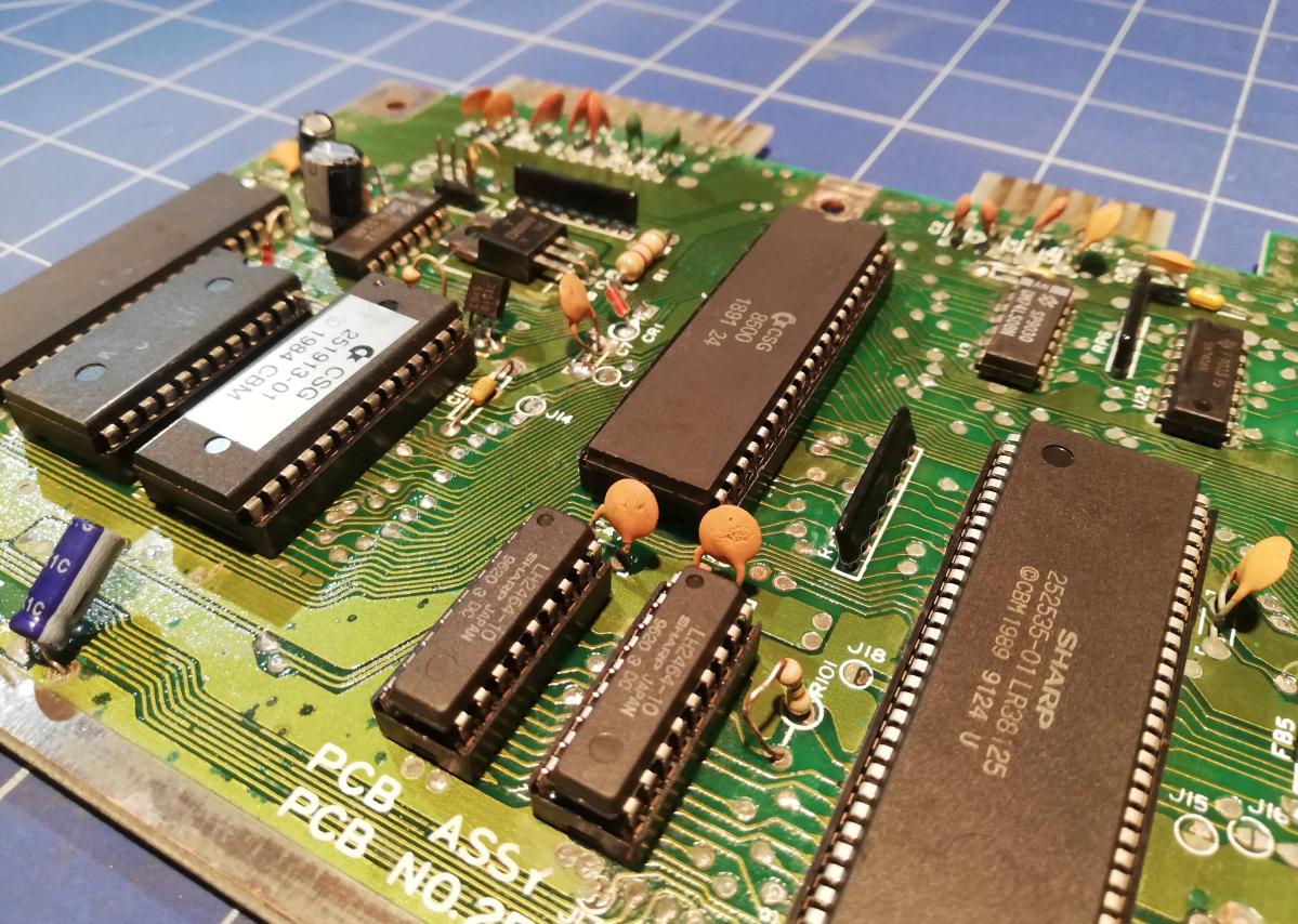
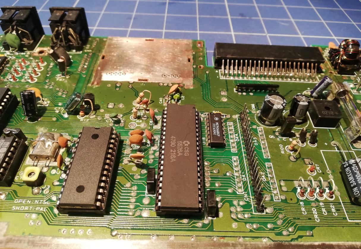
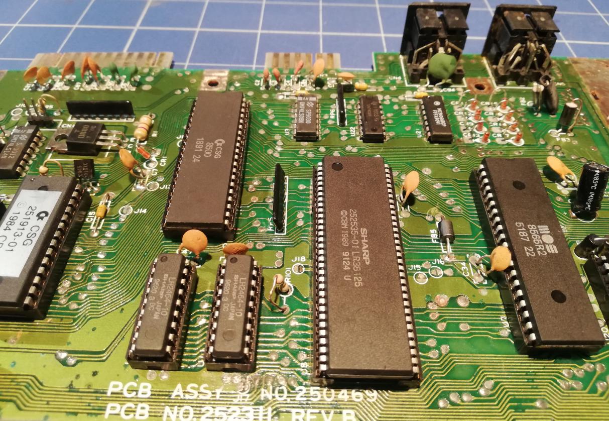
Of course, once in a desoldering frenzy, I also desoldered the RF modulator, joystick ports, a small CT1 trimmer as it was totally corroded, and most importantly a 252535-01 chip. I’ve also replaced a VIC-II socket just to keep things nice and clean. I’ve skipped the rest of the chips and sockets for later.
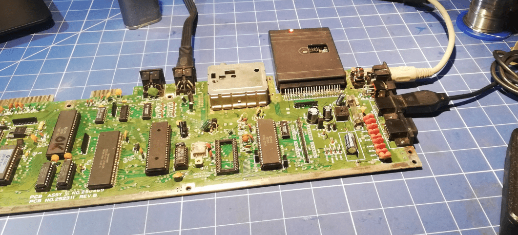
At this point, I was ready to test if it at actually works so I quickly connected PSU and video cable aaaaand…..
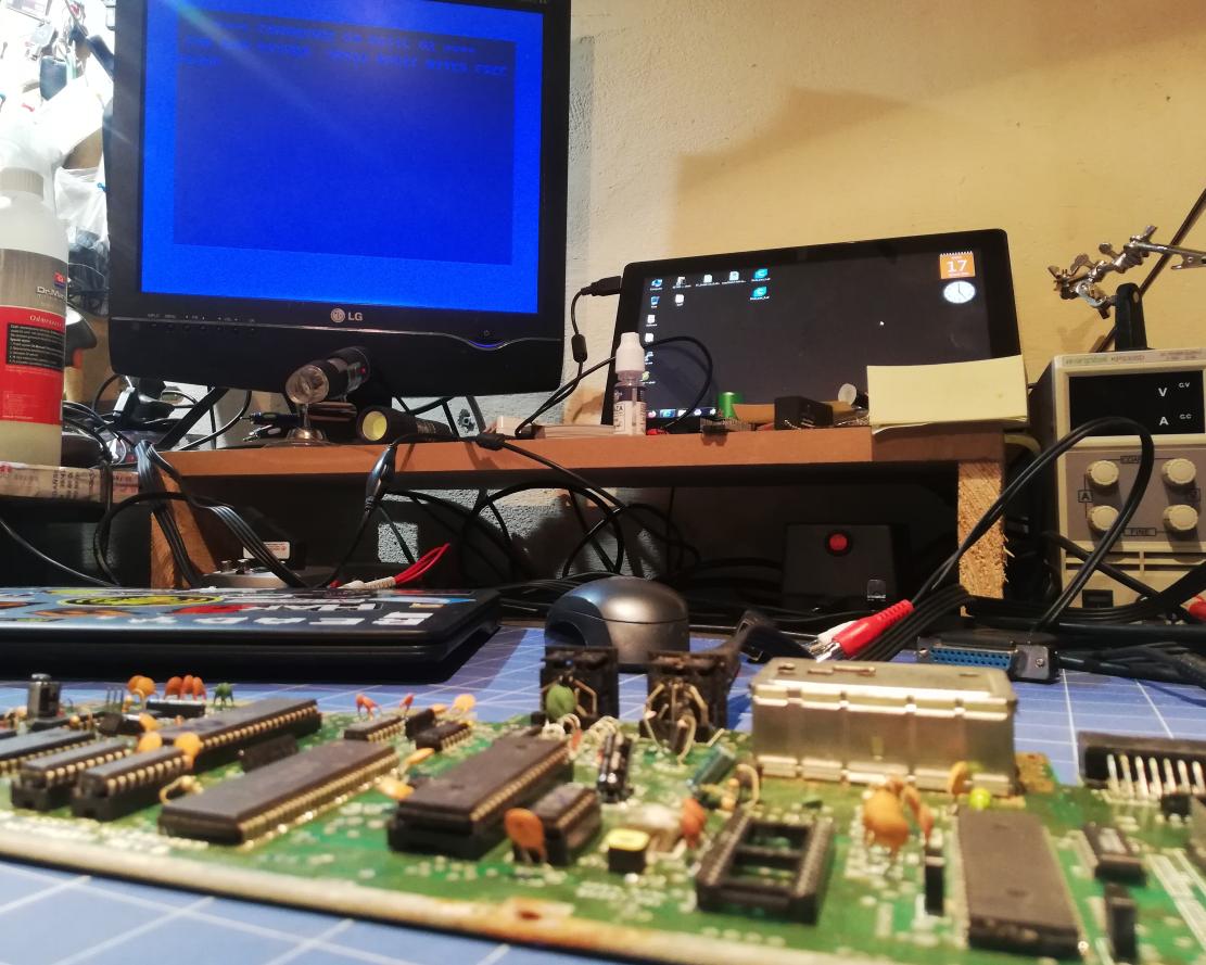
w00t! w00t! w00t! IT WERKZ! ……. NOT …. because of this …
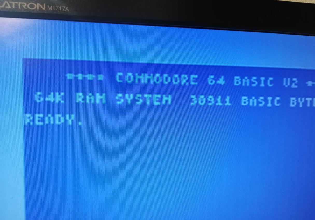
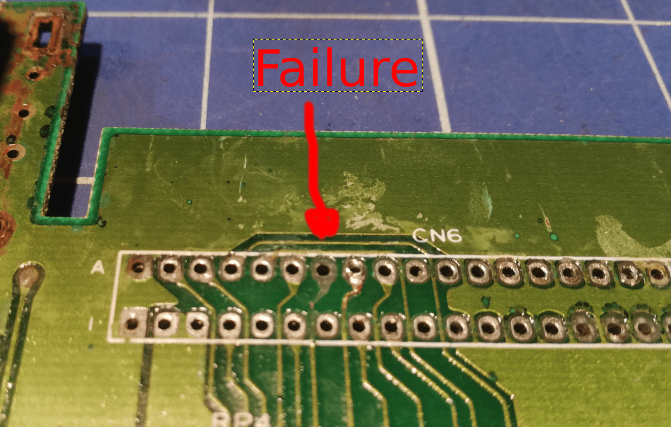
CHAR ROM Issue?
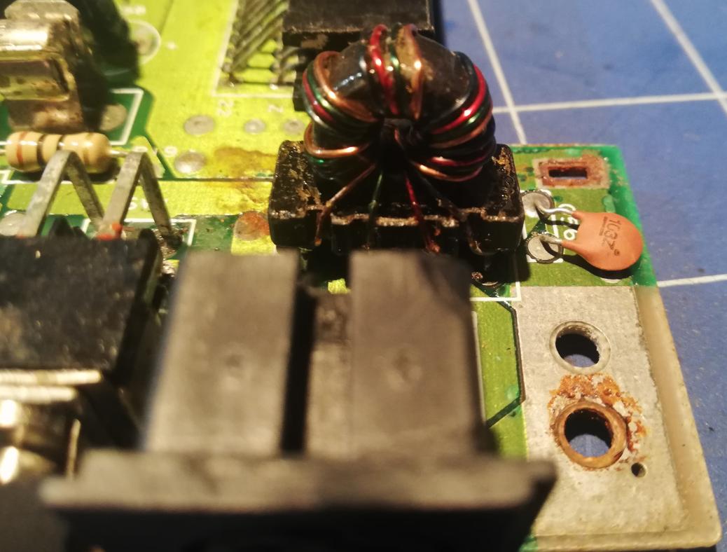
Ok, I must admit that I didn’t think logically and started desoldering CHARACTER ROM (as the main suspect) along with OS ROM (just to have it socketed). It turned out later that it was a silly and blind shot. Anyway, I’ve also dealt with other spots that required PCB reworks like, the main coil, SID socket, CIA, and a cartridge port which I’ll cover in more detail in a minute, but let me cover easy things first.
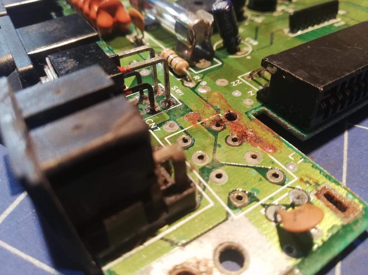
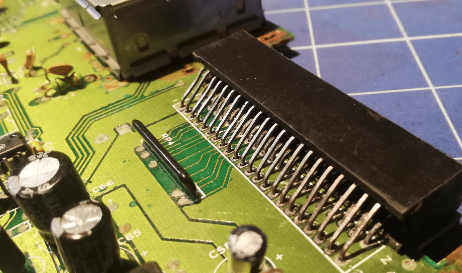
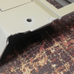
Cartridge port
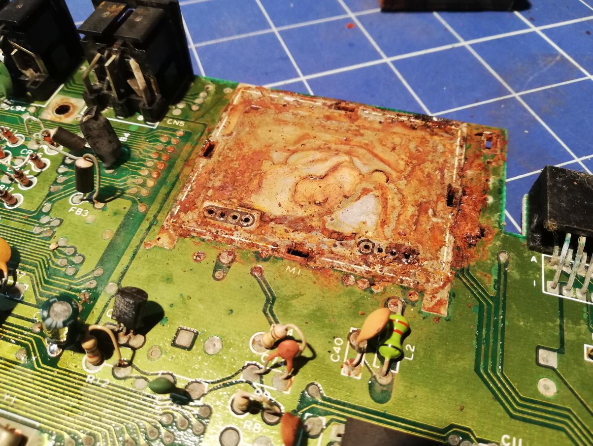
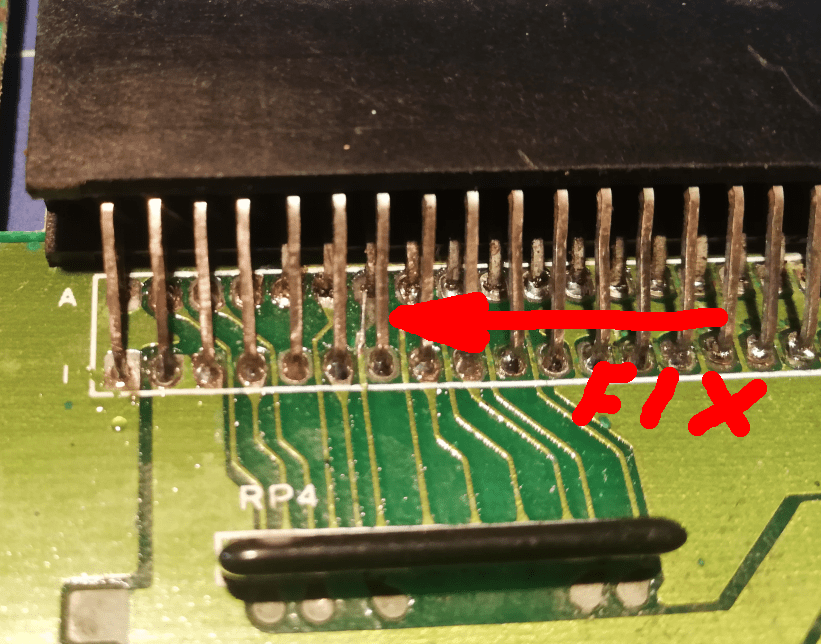
Ok, at this point I had to desolder the cartridge port as it was in a ridiculous state. Unfortunately, I’ve managed to kill one of the pads … nothing is unrefurbishable though 😀
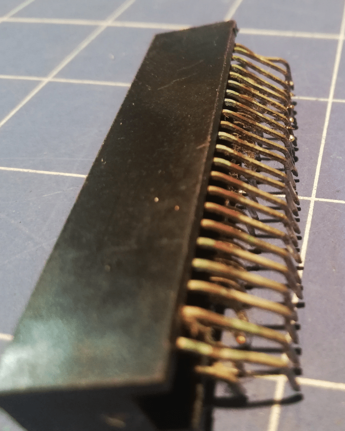
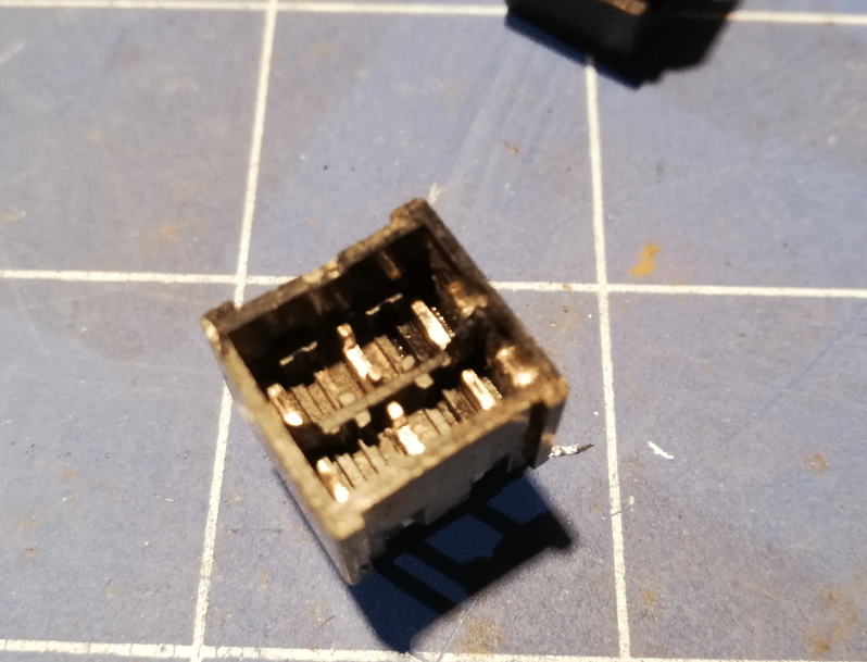
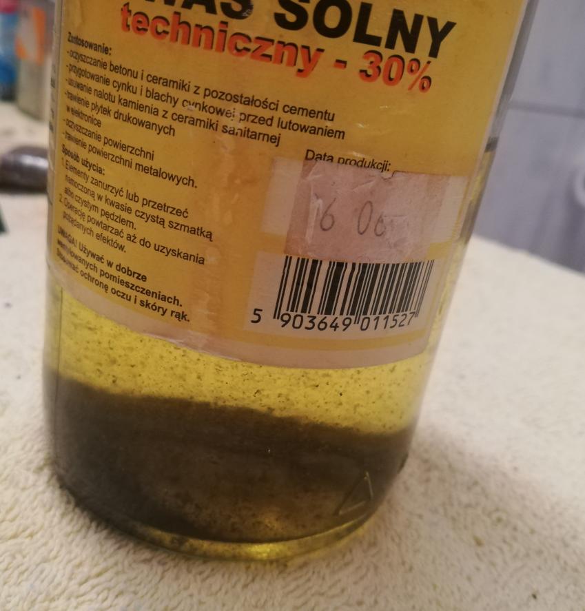
The idea to fix such a corroded port was to simply dip it in a mild (30%) solution of Hydro Chloric Acid. I always keep at least 500ml of dirty(used) HCL just for that purpose – to clean stuff.
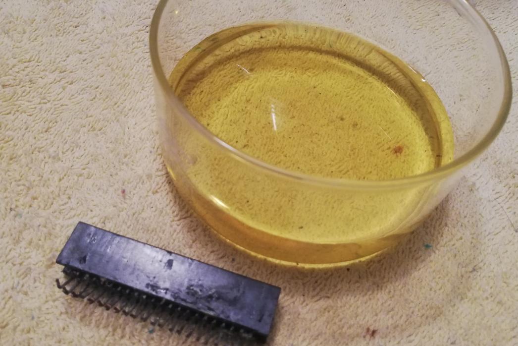
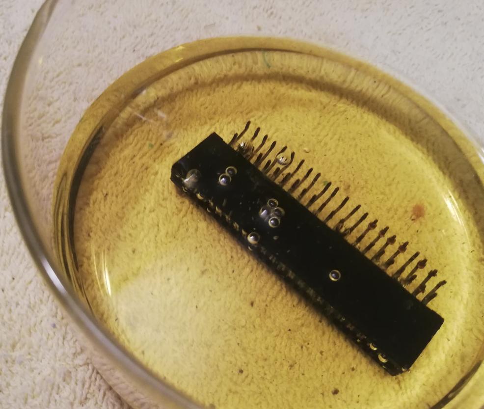
After a few minutes, the part was nicely cleaned so I could mount it and fix a broken trace by soldering a wire.
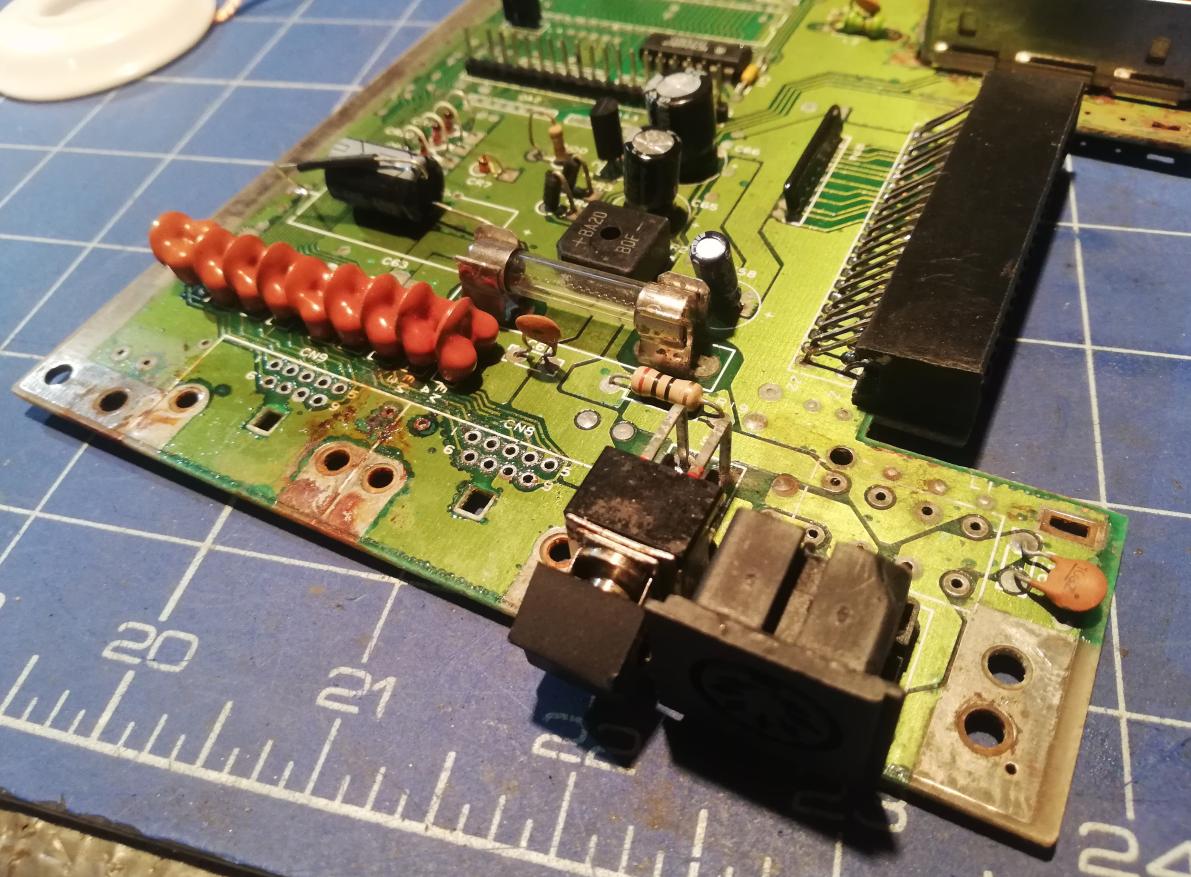
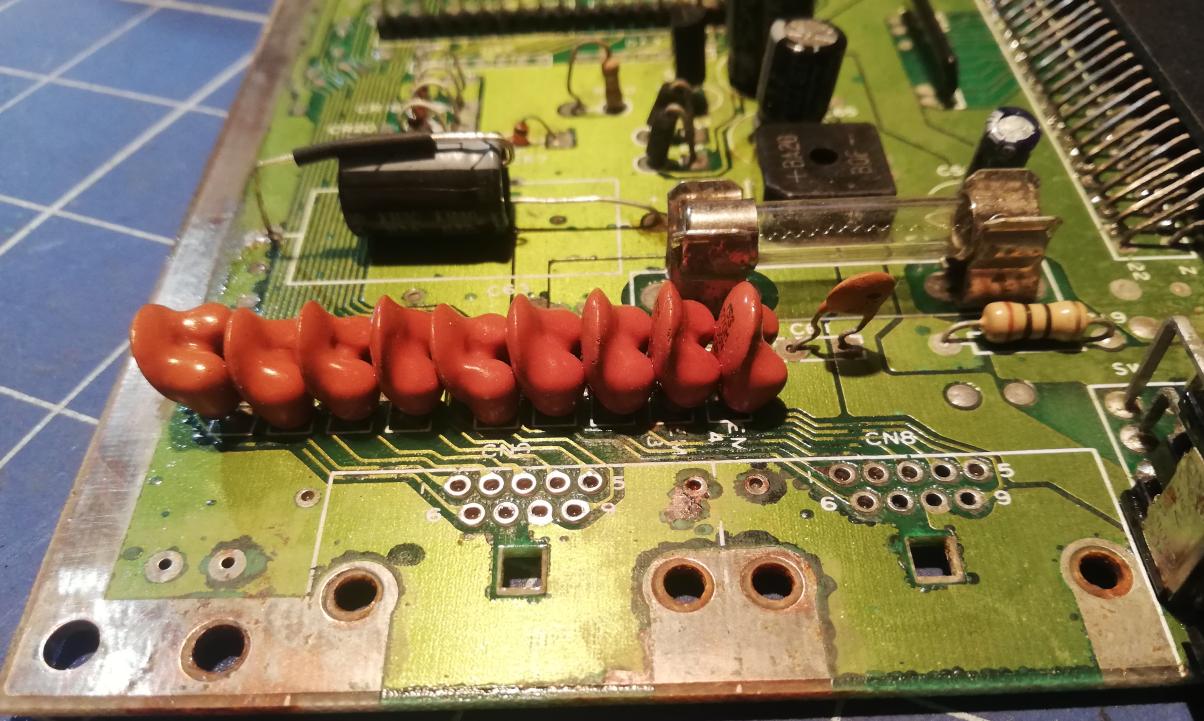
Before testing the cartridge connector I cleaned rust and other gunk that I’ve found under joystick ports after desoldering them.
Whaaaa!! boobs in a row! 😀
EasyFlash3 testing
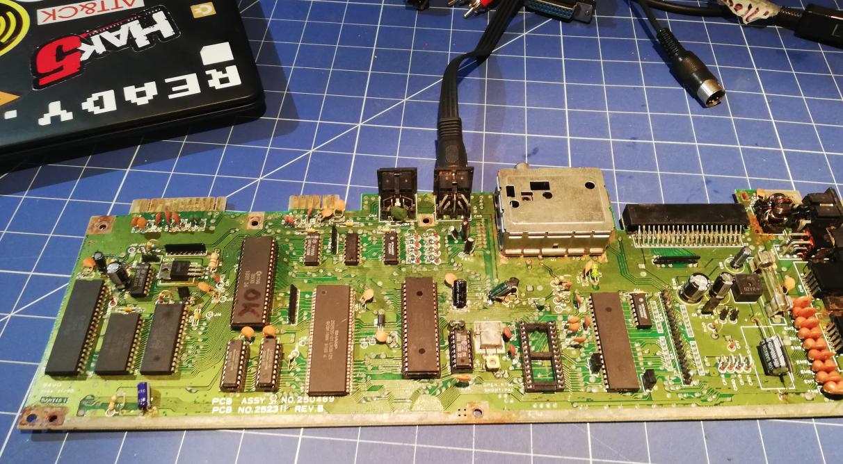
Testing time! 🙂
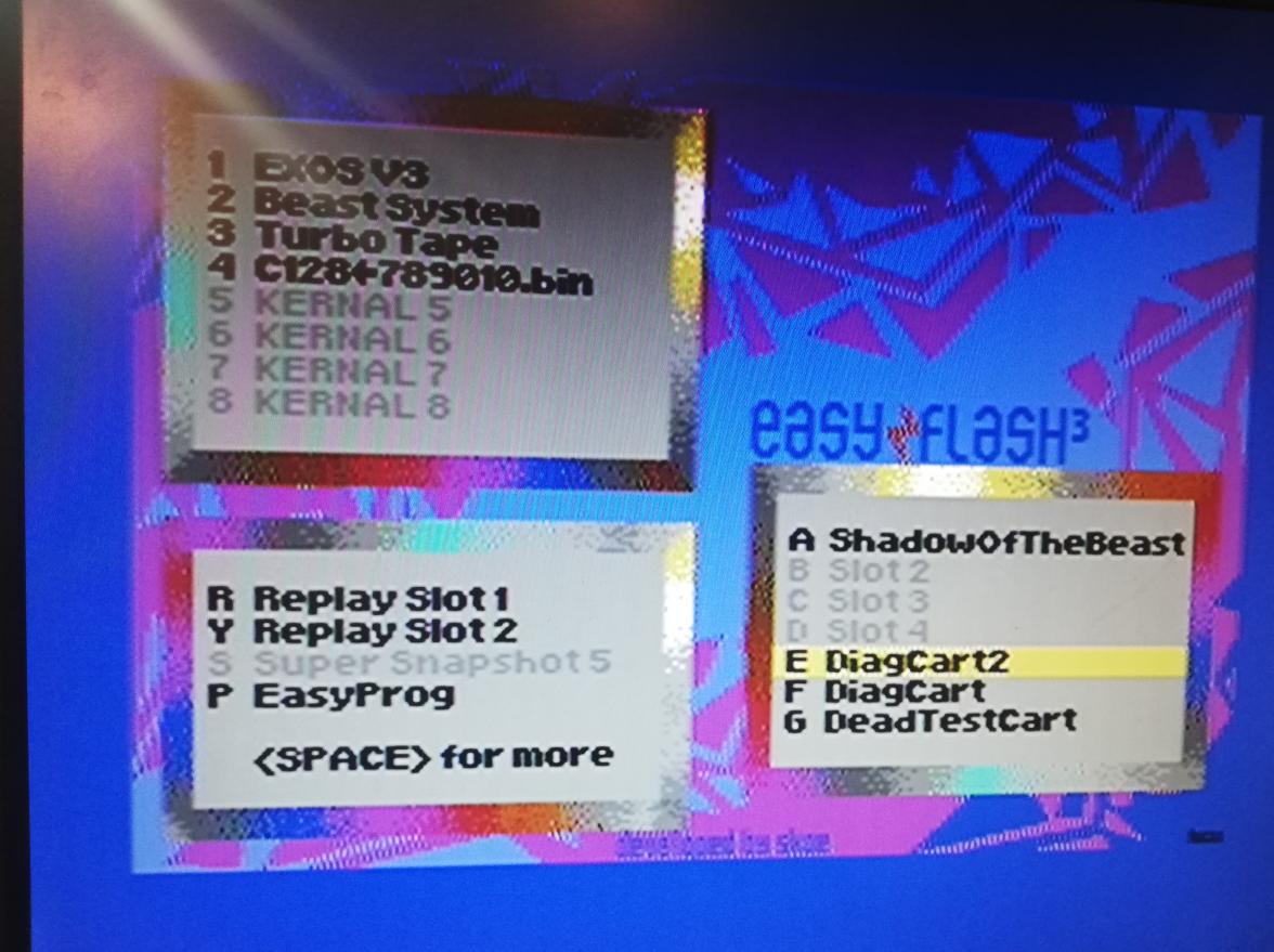
I’ve managed to load DiagCart that I had on my EasyFlash3 cartridge but I still had font artifacts all over the place.
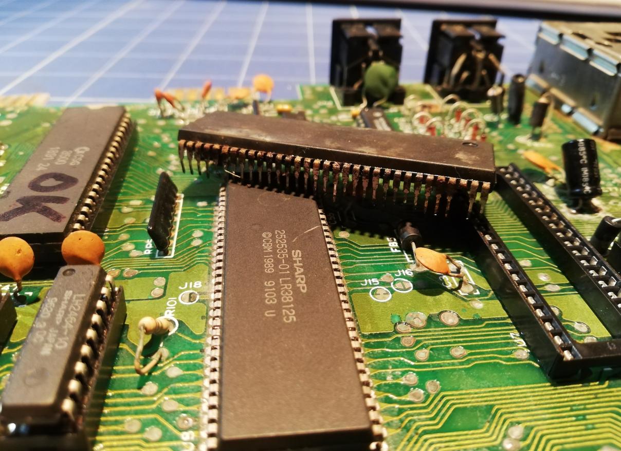
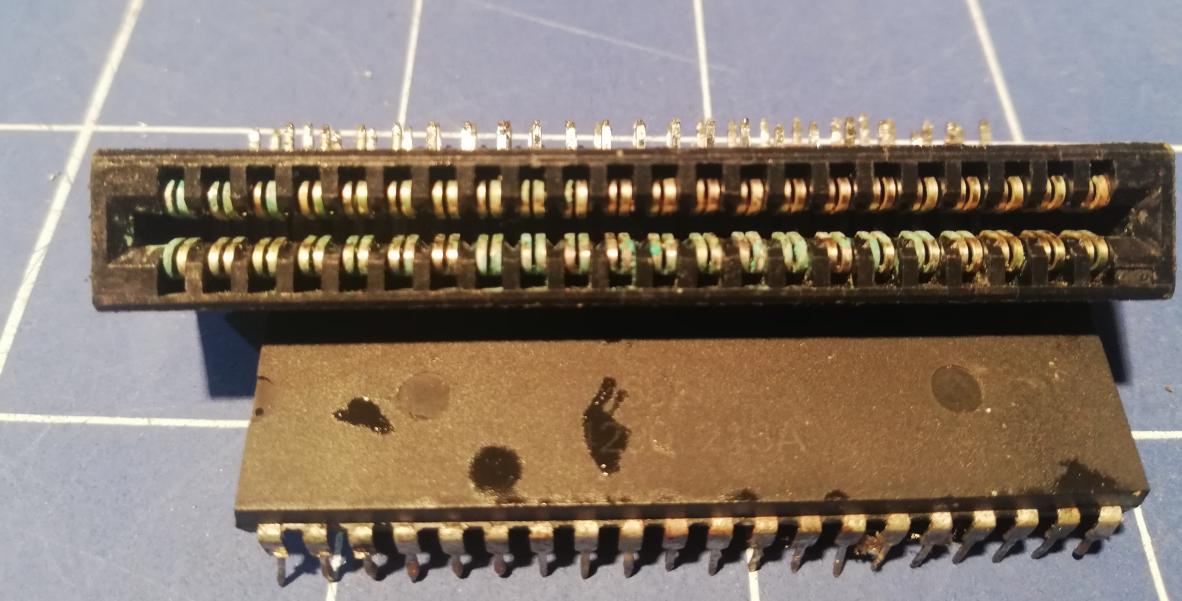
Aaaaand then it struck me what was causing such an effect … – a faulty 252535-01 IC. Looks like I’ve managed to replace a faulty IC with a … faulty IC.
Yes, that was the facepalm moment…

By the way, you can EasyFlash3 cart on my website.
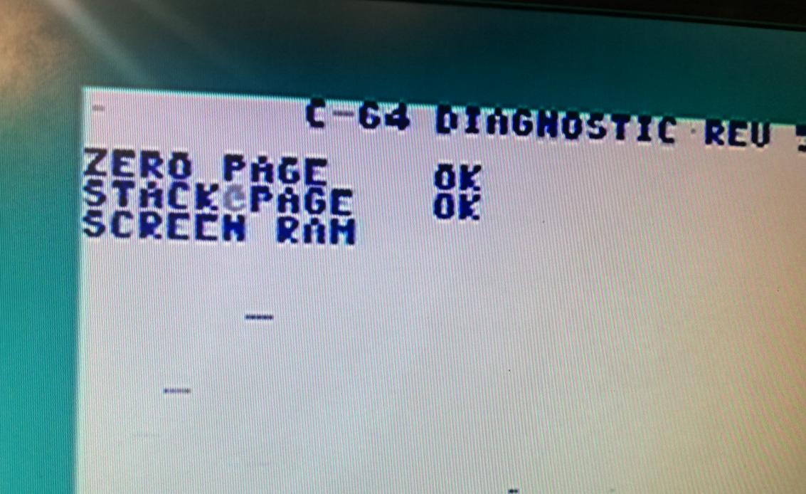
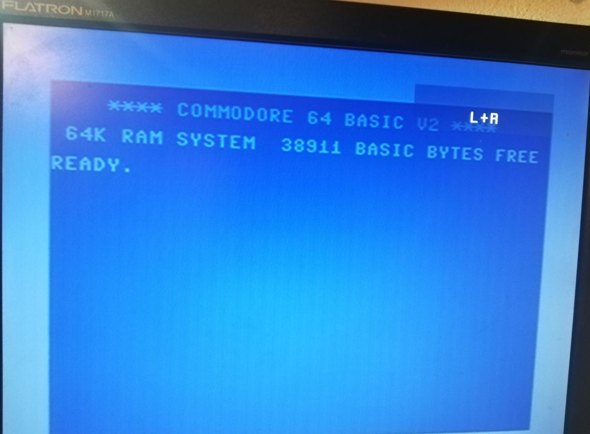
I had to desolder it again but this time I’ve socketed it just in case. Fortunately, it worked OK this time.
Woohoo! It finally fully works without issues 😀
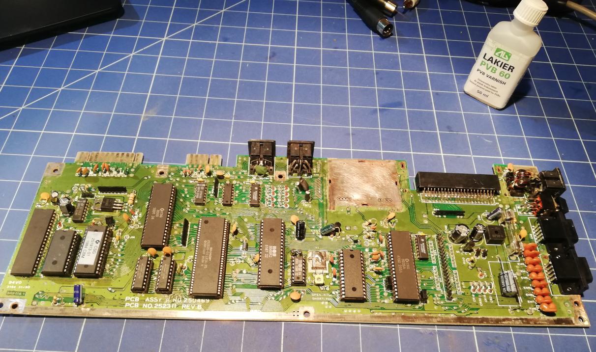
More cleaning
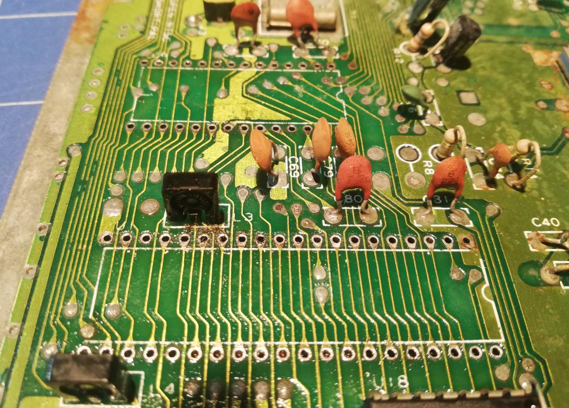
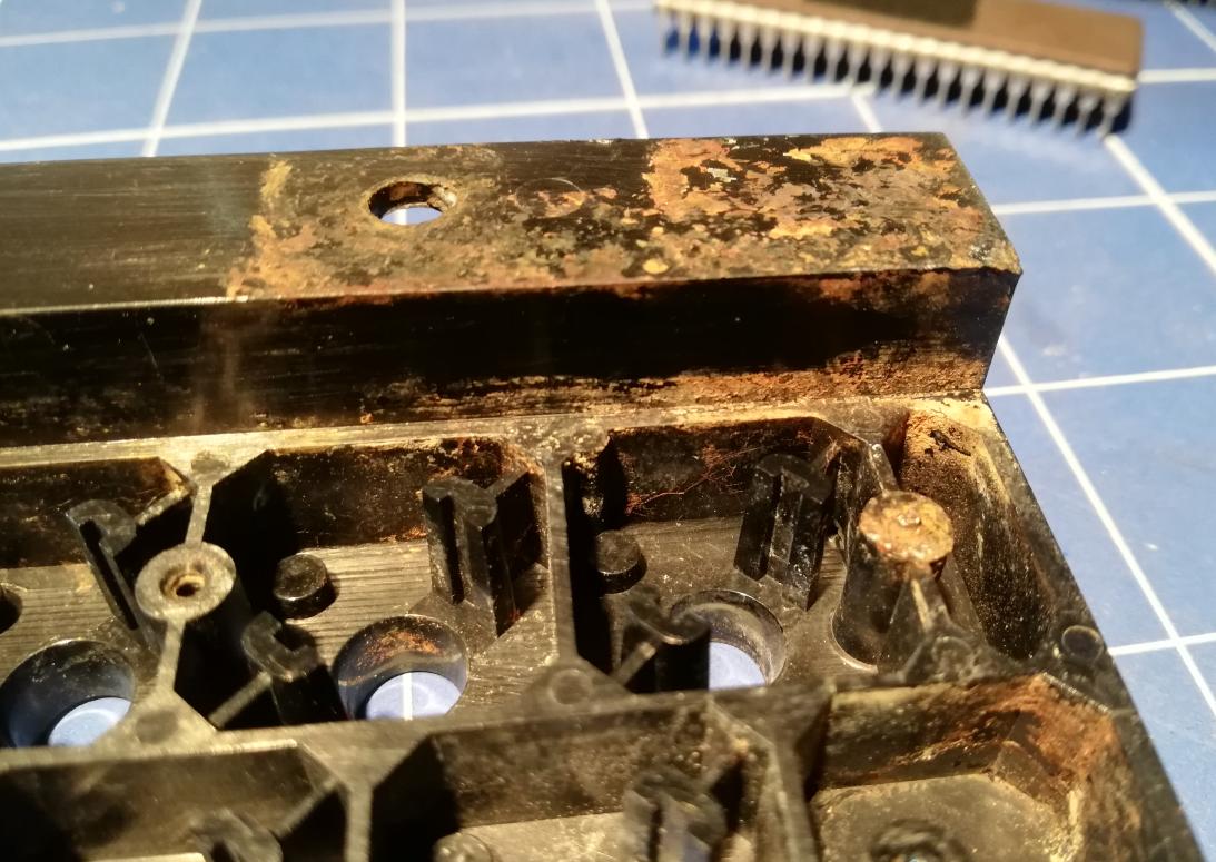
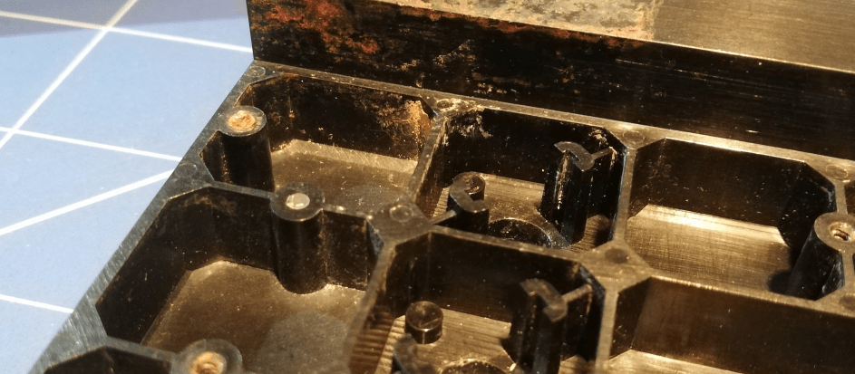
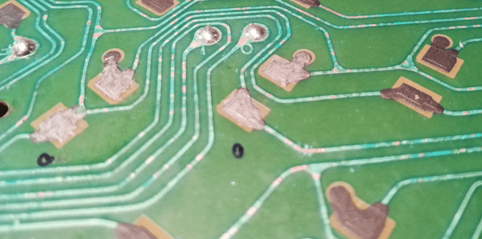
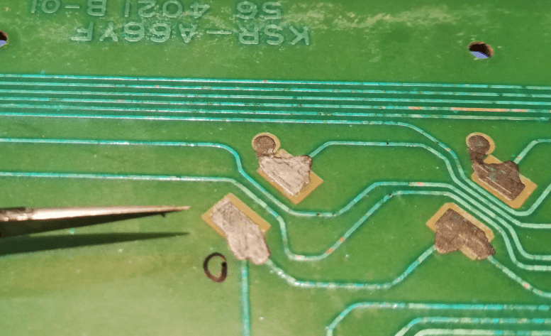
Now, with working electronics, I could start cleaning all remaining rust and dirt that was still covering a few parts of the motherboard. Usually, I am using a rotary tool with a small steel brush and 400-grade sandpaper. This part took me quite a while. After solid scrubbing, cleaning, and sanding, I’ve applied a thin layer of PVB Varnish acting as a solder mask substitute. Below, some pics are shot after cleaning and before PVB Varnish treatment.
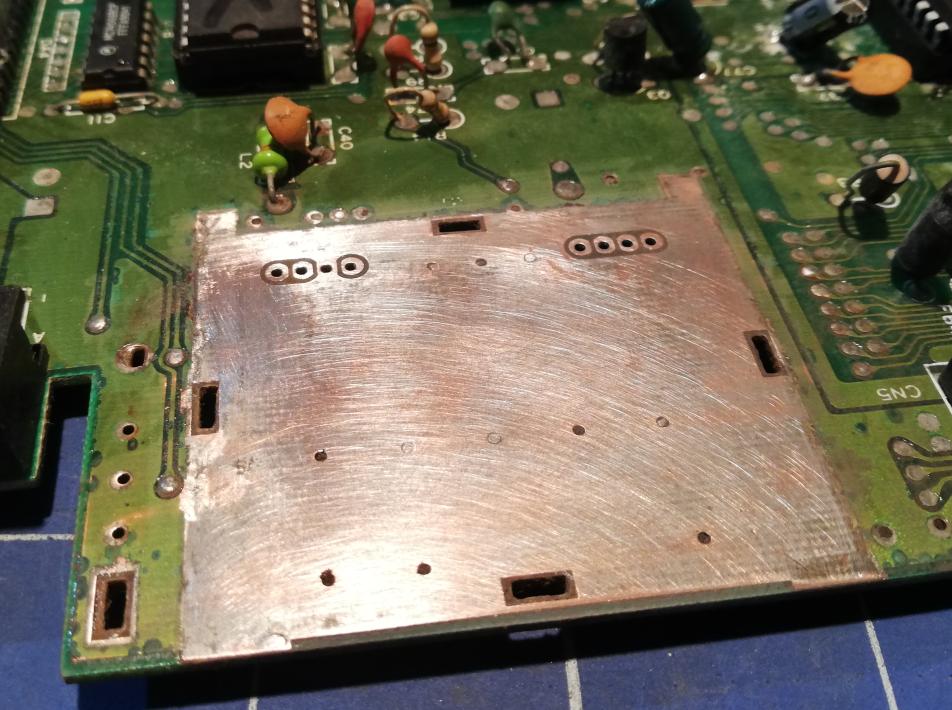
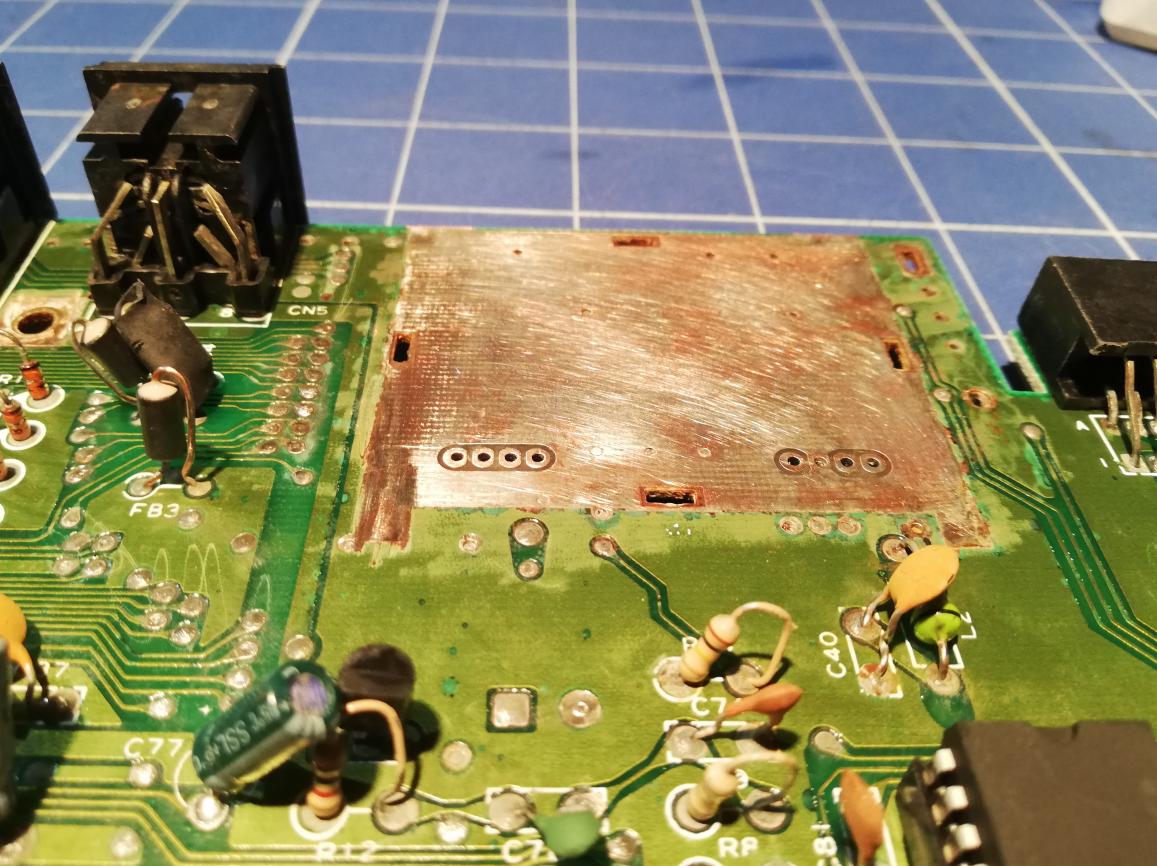
Below pics were shot after applying PVB Varnish.
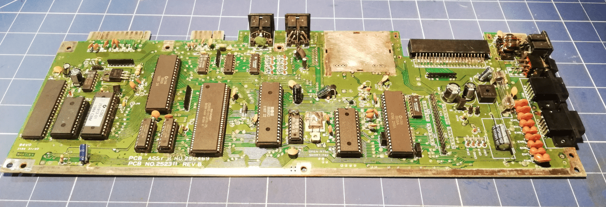
The last picture is with an RF modulator and cartridge port cover already in their respective places.
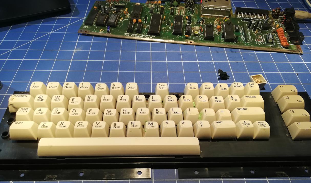
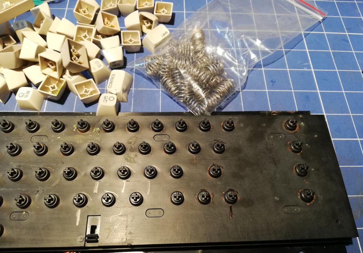
Keyboard fixing
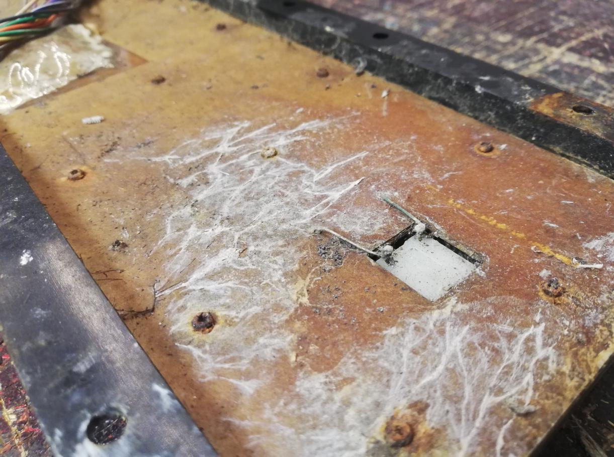
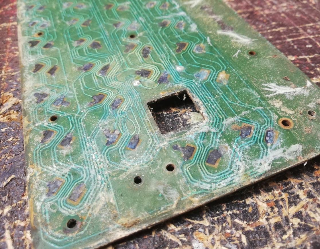
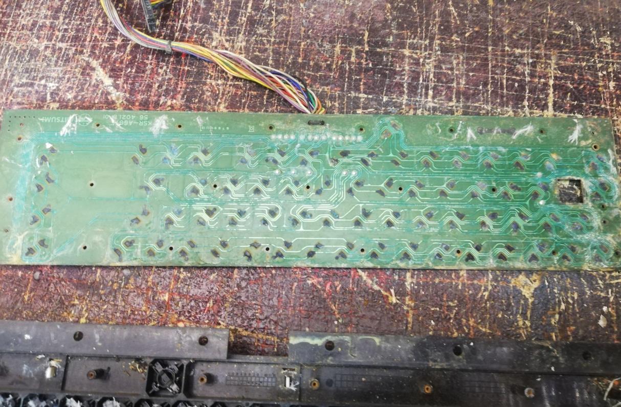
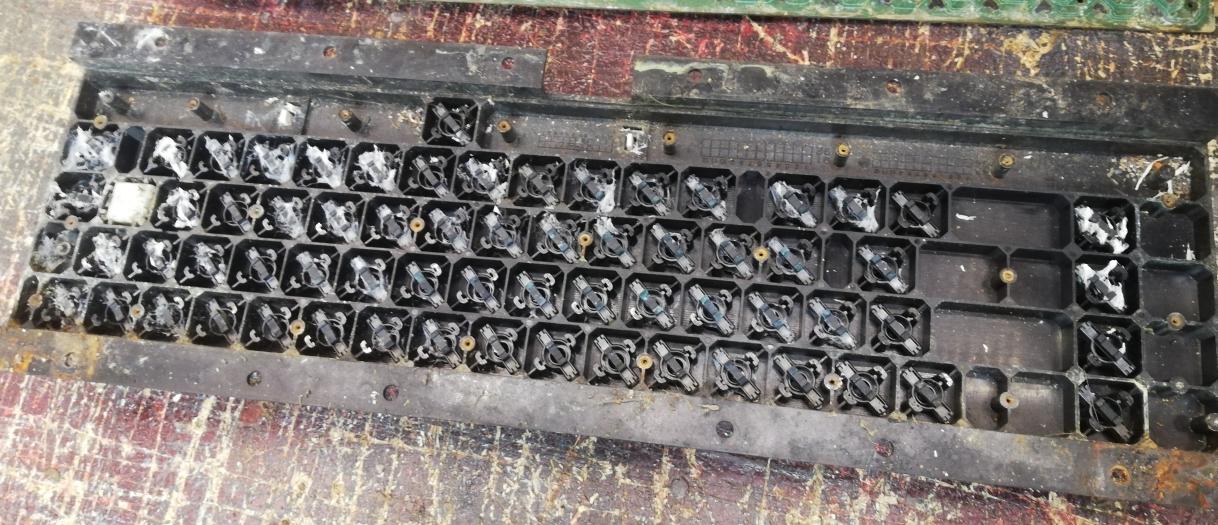
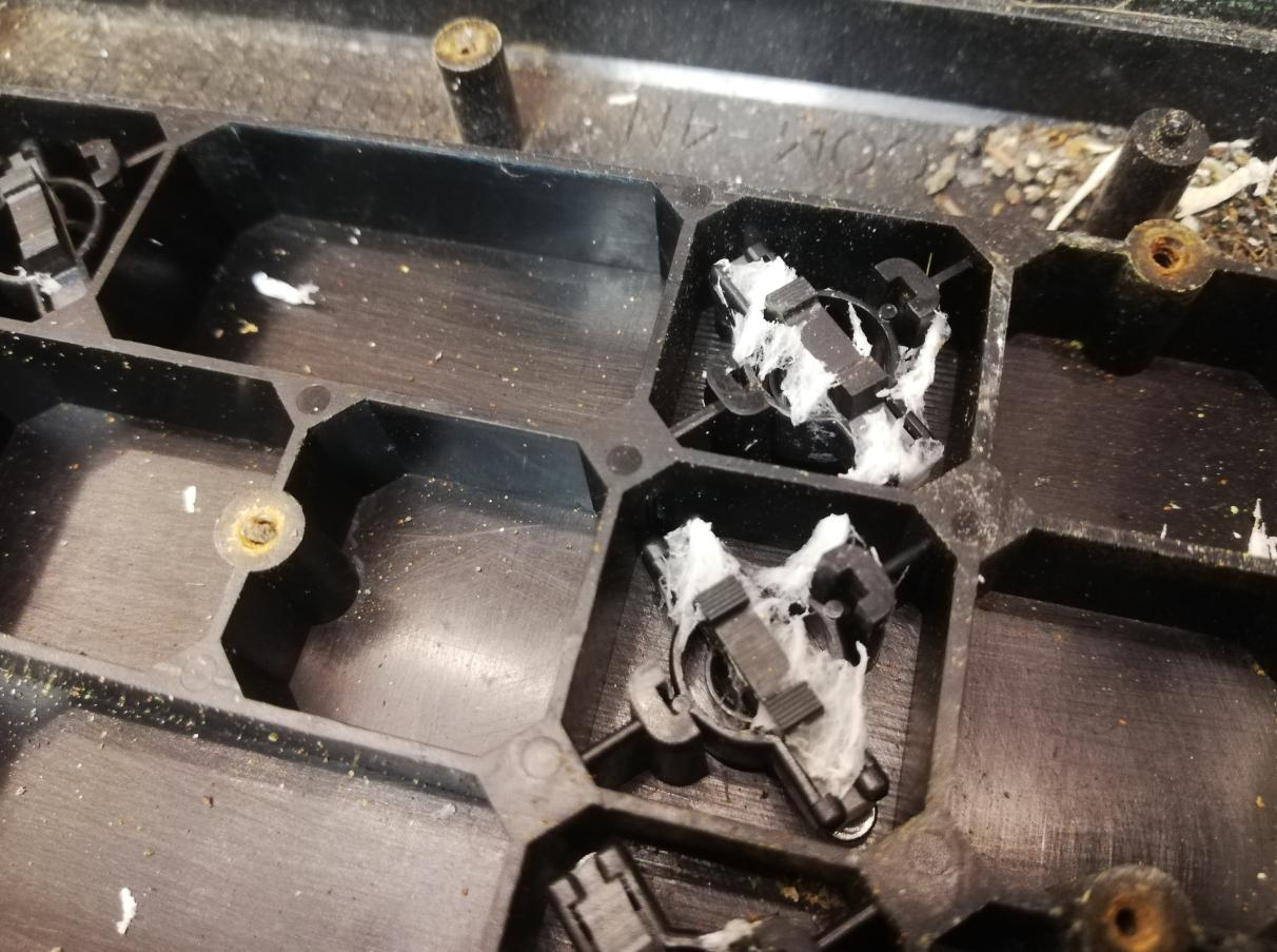
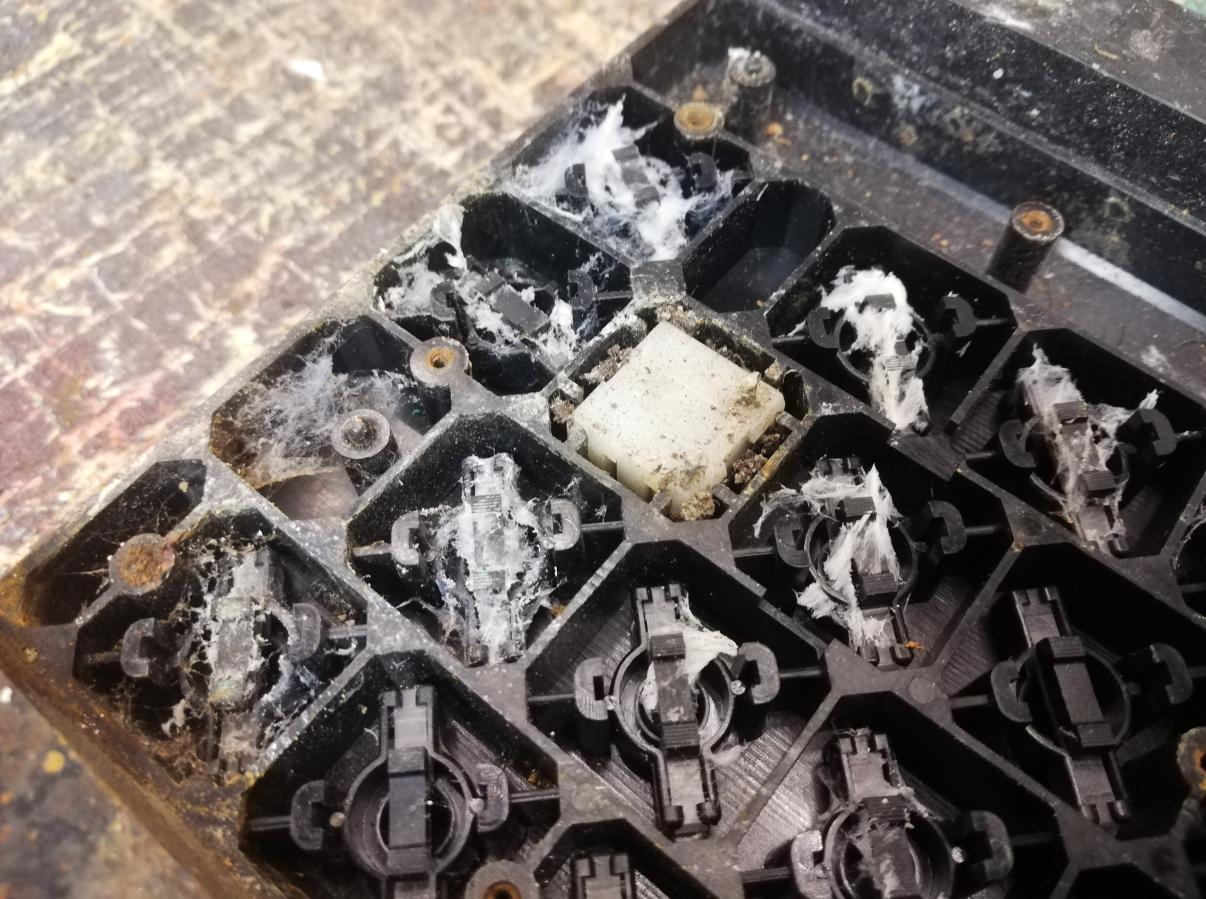
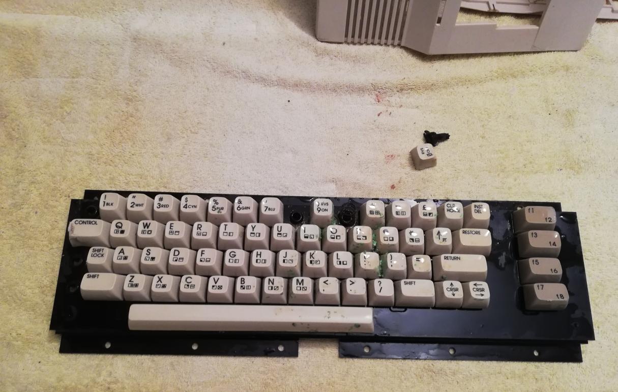
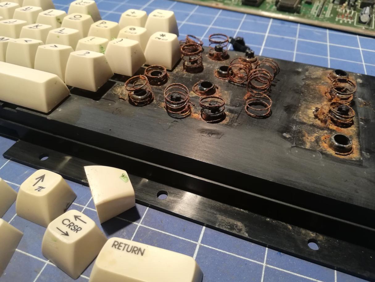
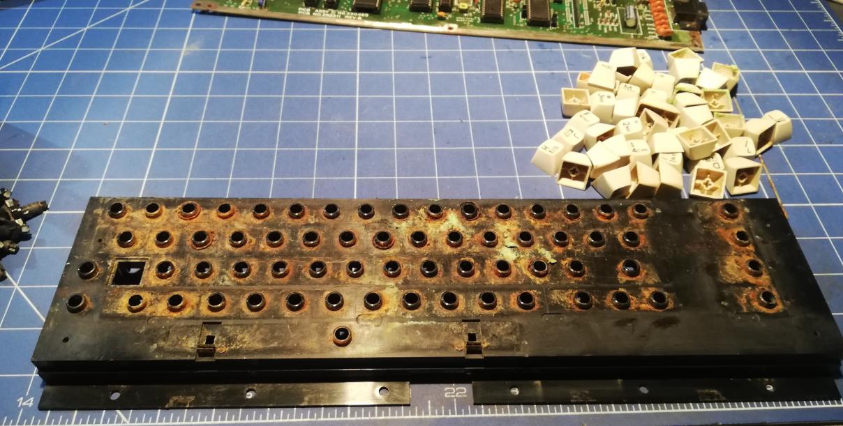
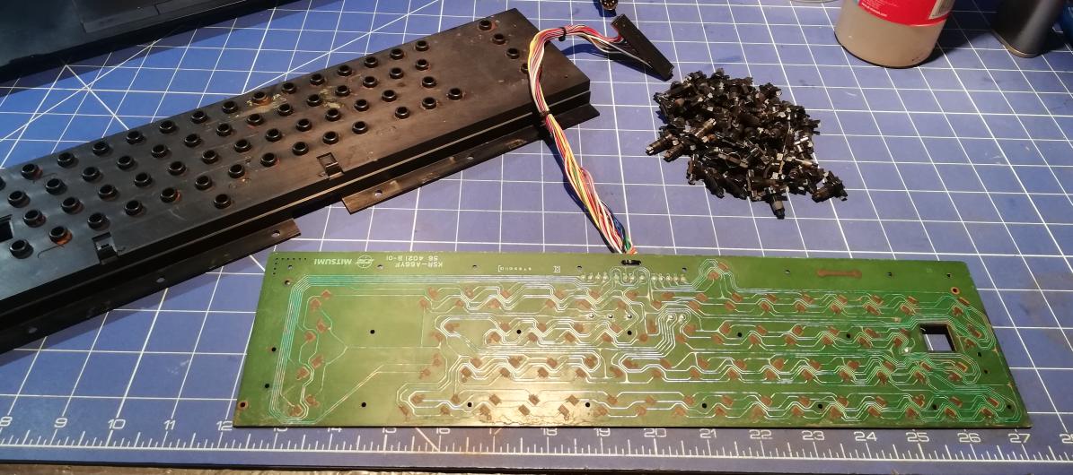
Ok, let’s fix a keyboard now! I had to disassemble it first. That was kinda painful to see such damage 🙁
PCB was covered with some sort of spider web. Inside I’ve also found a lot of spider webs and other abandoned bugs houses.
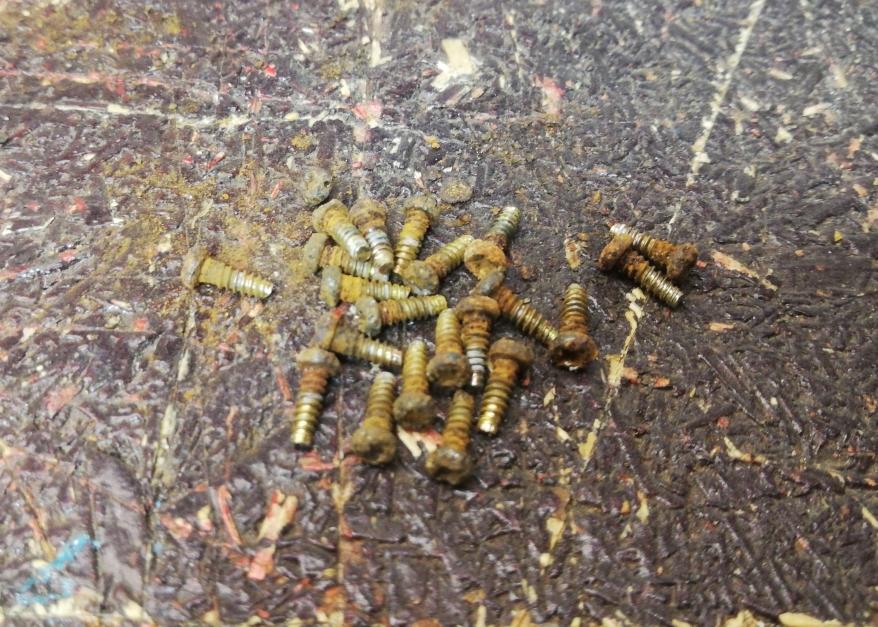
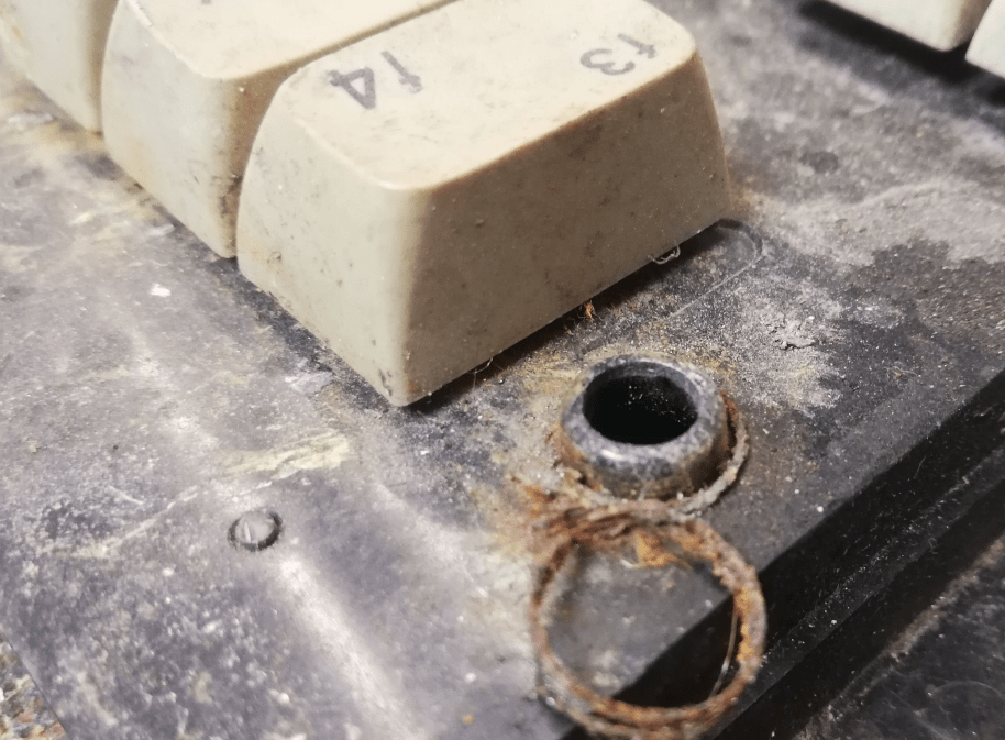
A lot of screws were completely corroded and super hard to unscrew without damage. Some screws snapped off but luckily I had spare screws left from other projects.
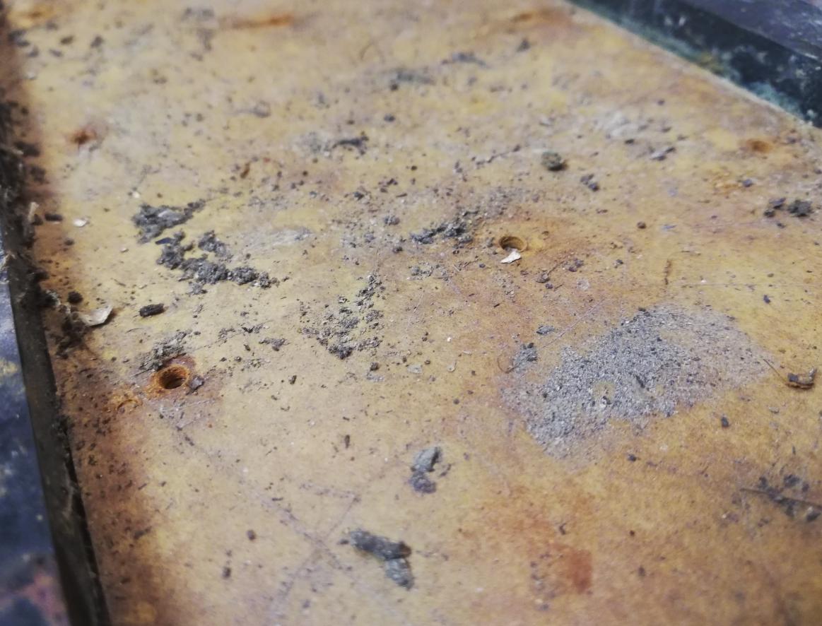
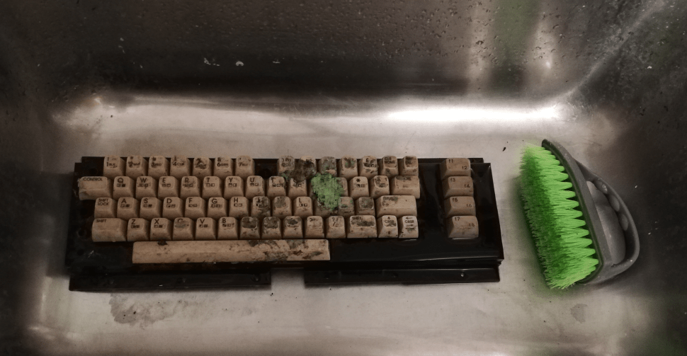
Even more cleaning
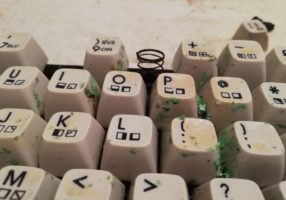
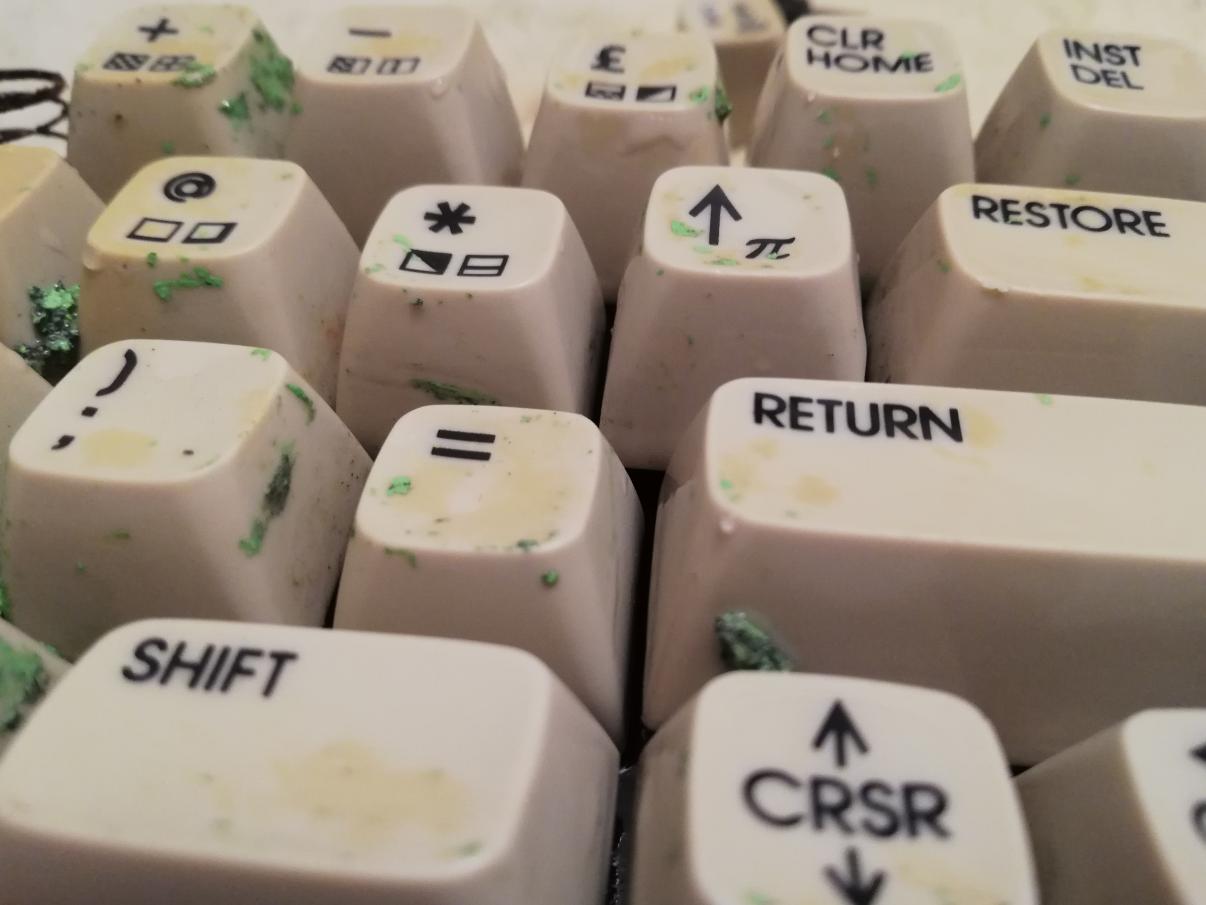
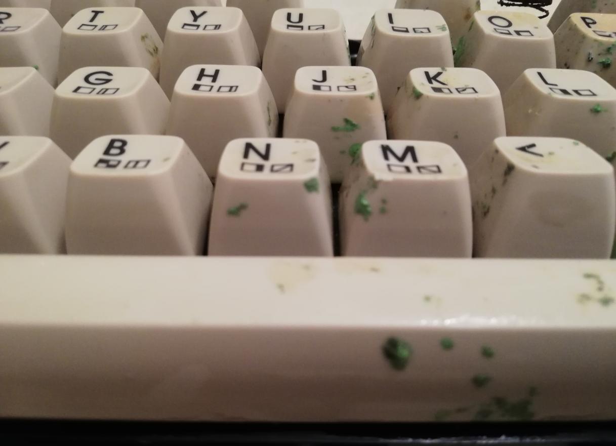
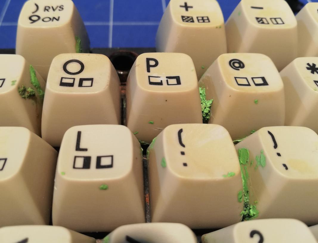
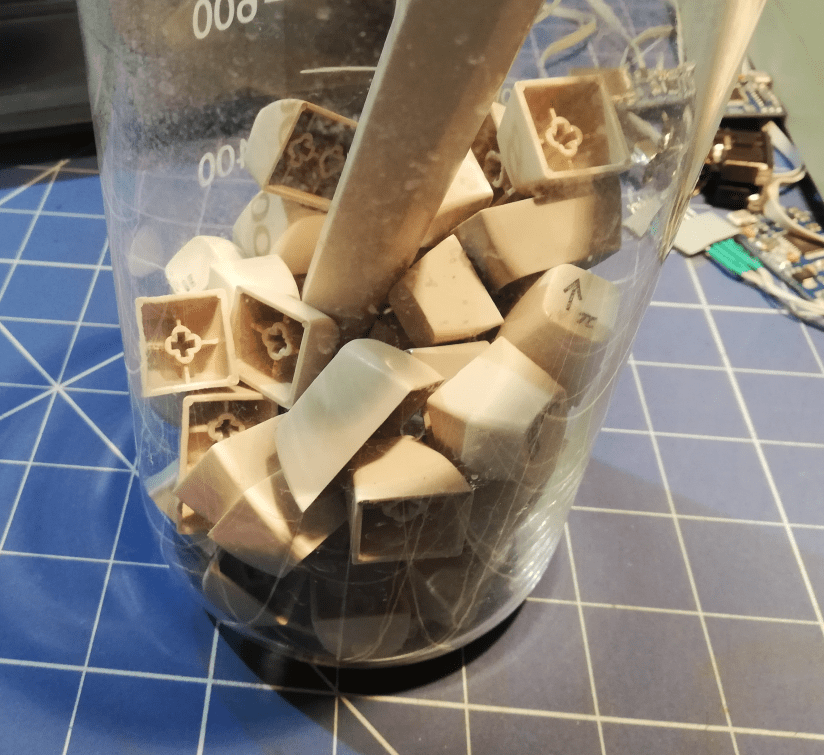
Time to start the serious cleanup. At this point, I was quite certain what is this weird looking green gooey that covered some keys. It was an old paint that fortunately was … old. Such old paints become soft when treated with heat. That is what I did while trying to remove it. I heated it with a stream of hot water until it became soft and easier to remove in big chunks.
I’ve also cleaned all keycaps using my standard method – brush+hot water+detergent.
Small digression. I always wonder why a lot of Youtube folks clean each key individually. Is it for the show? to make a video longer? I’ve no idea!
Cleaning a pretty dirty keyboard never took me more than 5-10 minutes (well, except for this very keyboard) and I don’t understand why people spend hours cleaning each key individually lol 😀
Even more cleaning … stage 2
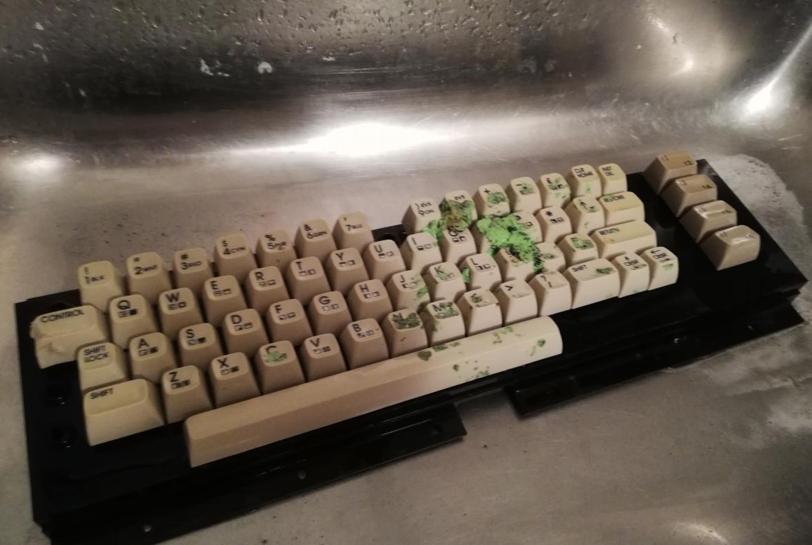
After removing most of the “wasabi sauce” I’ve discovered a serious yellowing where it used to be. This means that paint came into a chemical reaction with ABS plastic. This is an important observation since it was covered by paint and the sunlight didn’t touch it at all. Another proof is that UV light is not the main cause of yellowing.
Ok, now I was ready to run STAGE 2. Time to disassemble keycaps and clean them one by one.
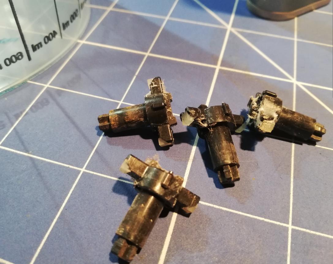

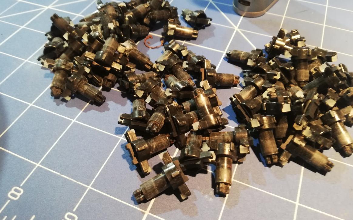
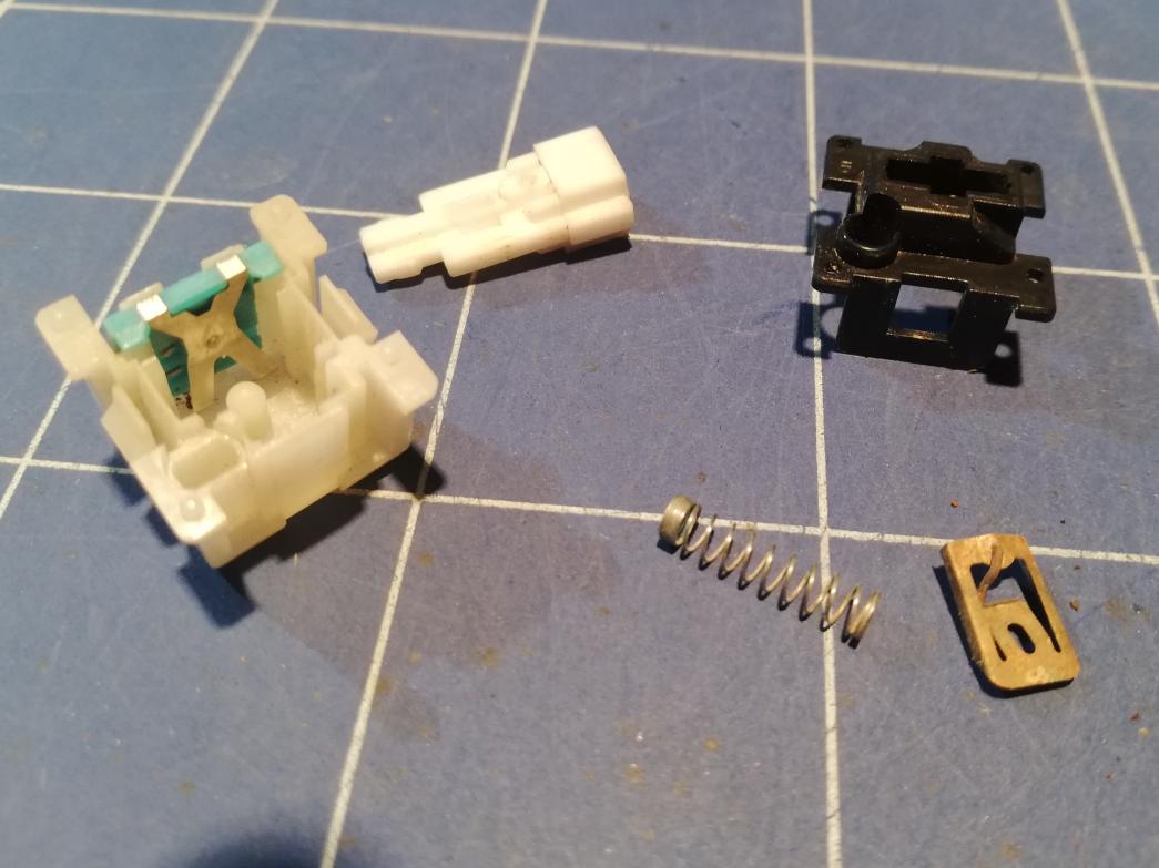
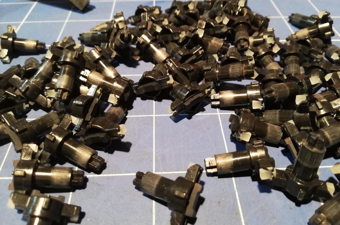
Keycap springs were destroyed by rust.
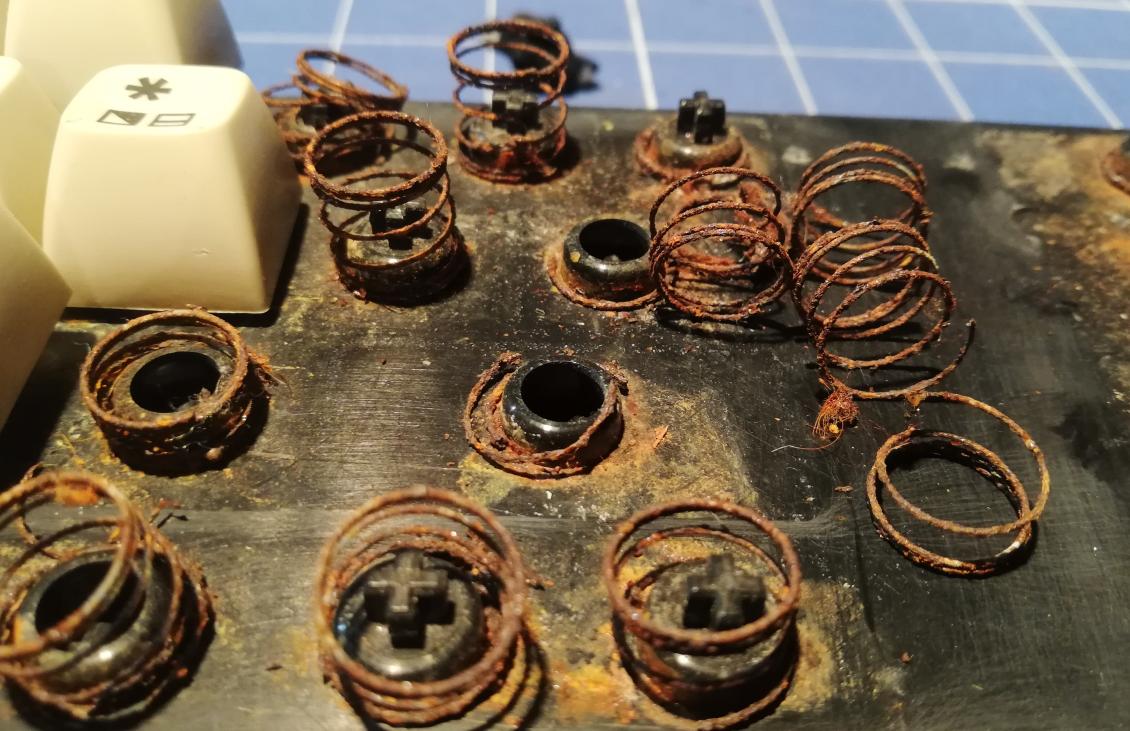
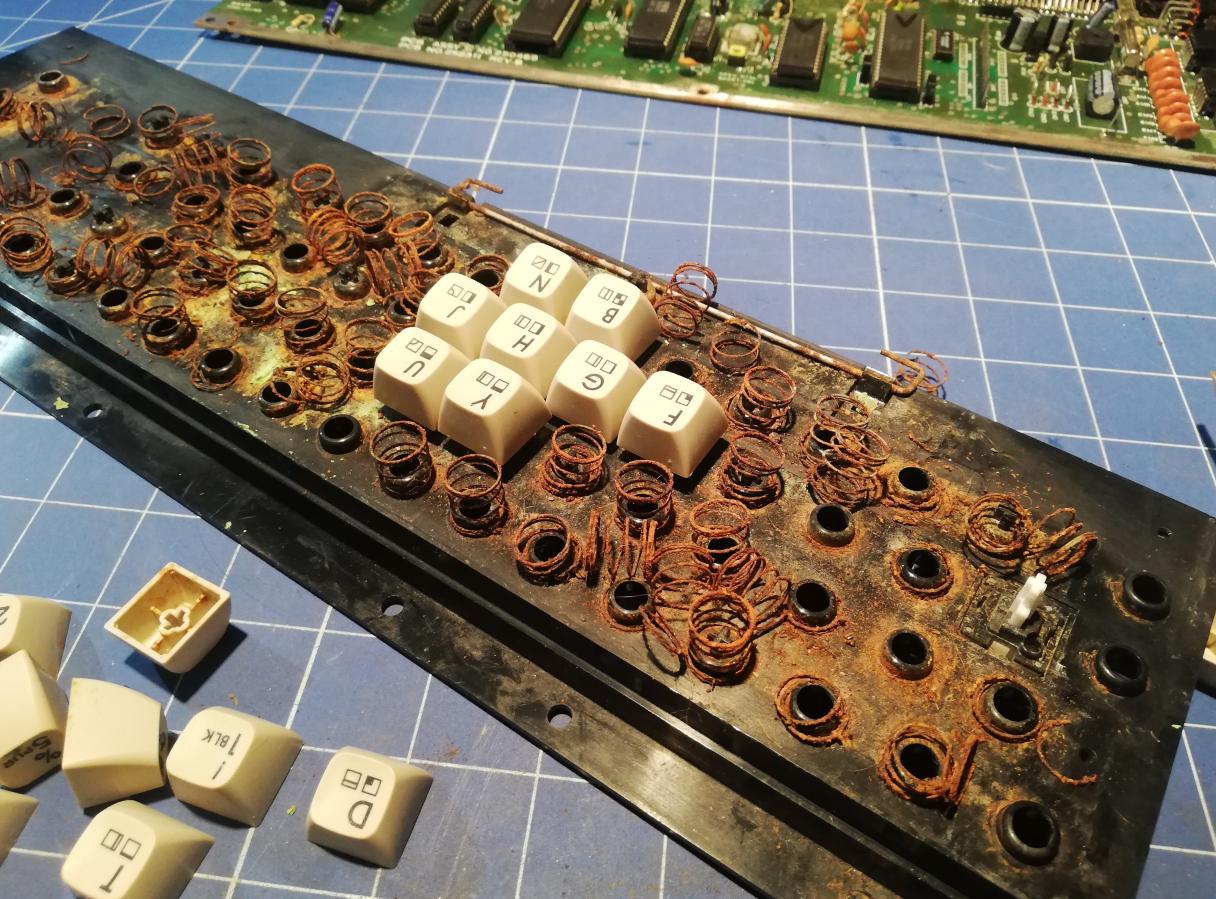
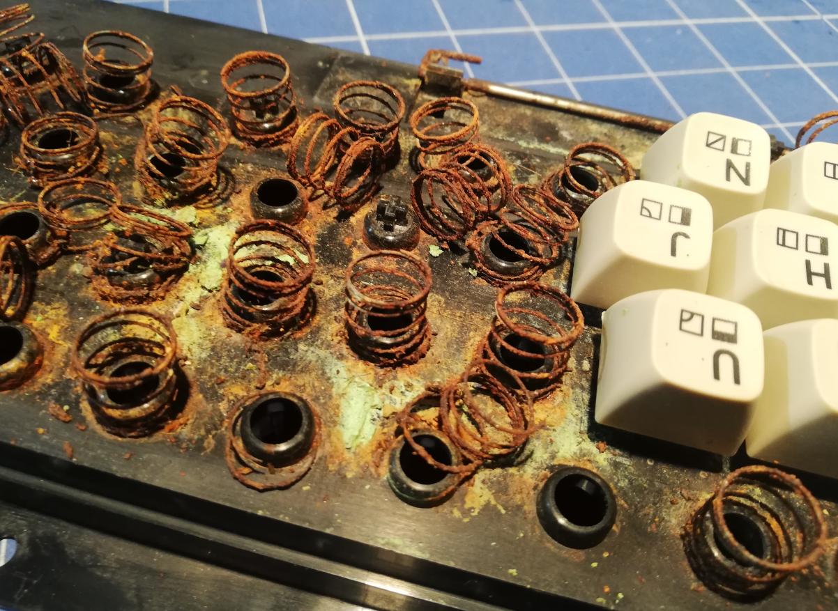
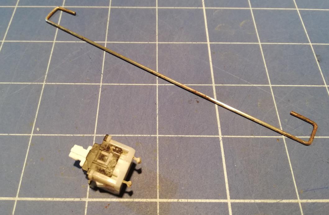
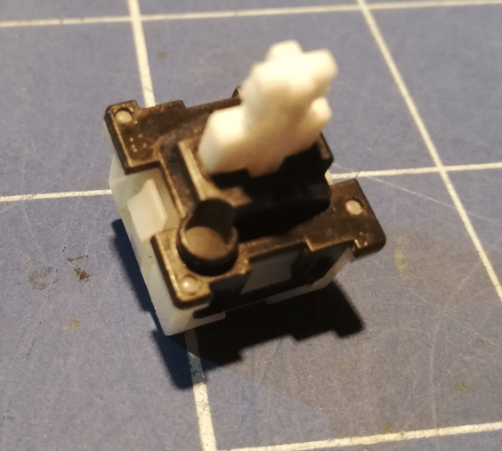
Everything was disassembled so I was ready to clean and fix whole that mess. I started with the Scroll Lock key which was dirty and required serious cleaning. It was completely disassembled and cleaned with a bit of mild solution of Hydrochloric Acid and assembled back afterward.
Then I had to take care of the remaining of screws left in a keyboard holder. I’ve removed it with a soldering iron. I’ve simply heated the stuck piece and removed it with pliers.
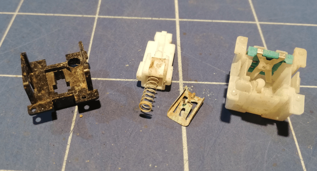
Ok, final KB parts cleaning …
Ok, everything is ready for cleaning.
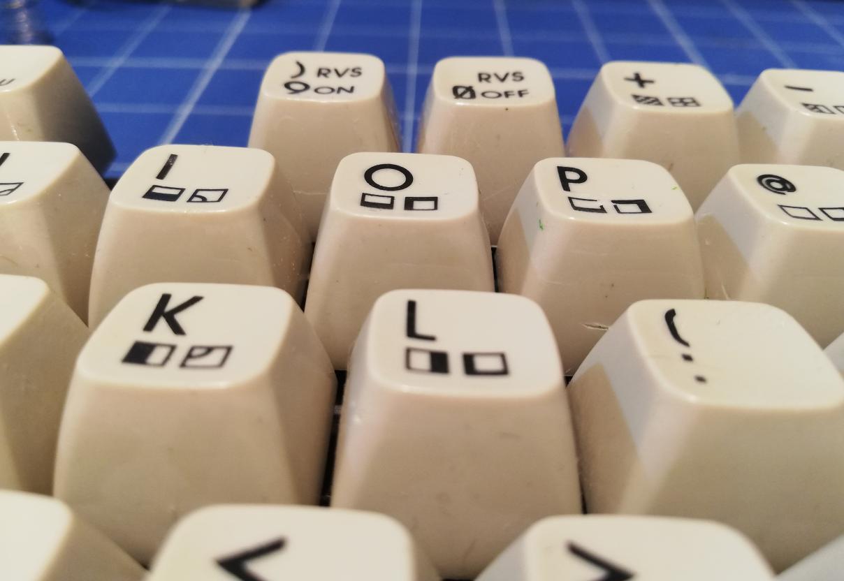
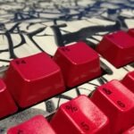
Keycaps took a retr0brighting bath 🙂
Graphite trick
I’ve tested a keyboard PCB and it turned out that some keys are not working. At first, I thought that the traces are broken but after some measuring, it became obvious that the pads are not conducting anything. My method of fixing it is to first cover such a graphite pad with graphite from an HB pencil. This has to be done very gently as the original graphite is super brittle.
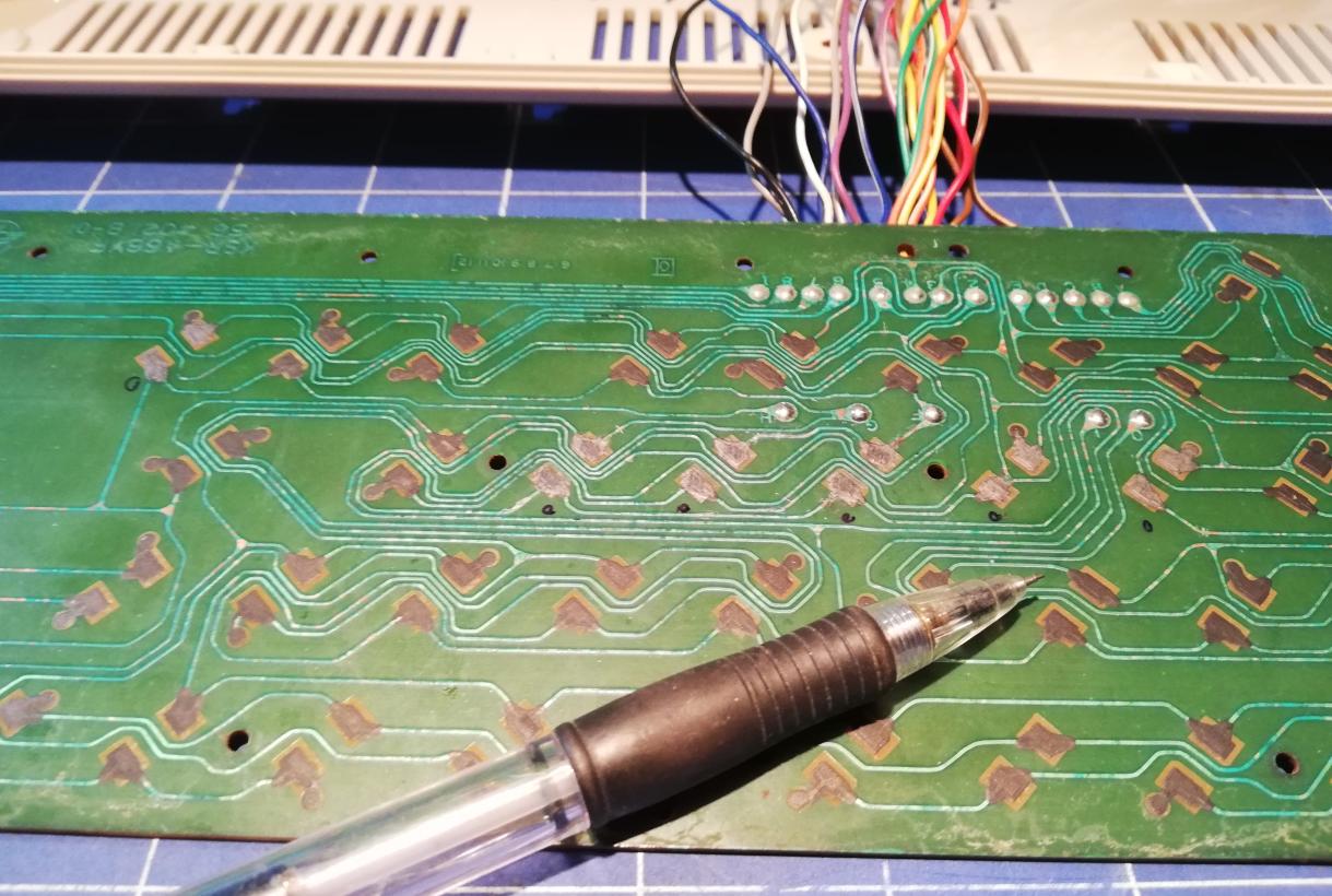
Then I used a sharp and pointy tool to very gently scratch a pad.
After the above procedure, all keys started to work again 🙂
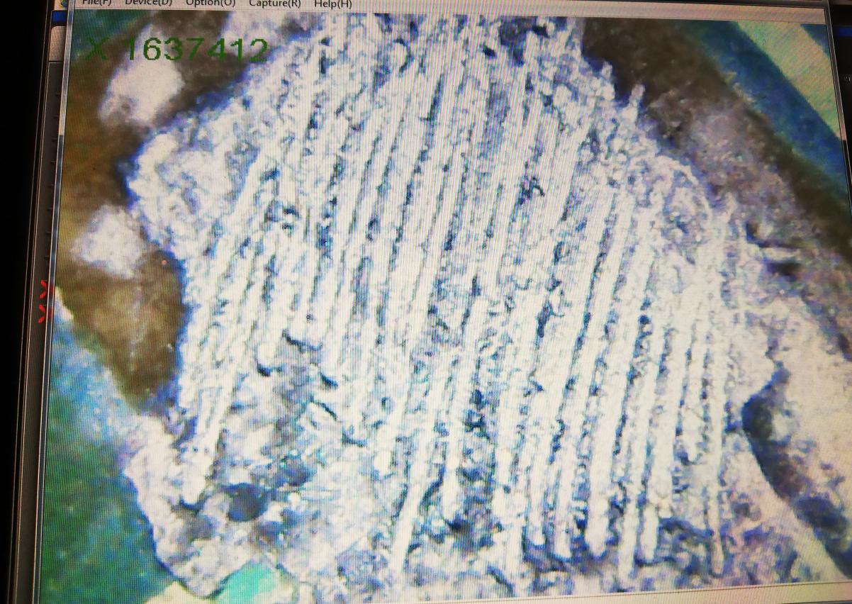
Below are some micro-camera closeups.
Original graphite pad
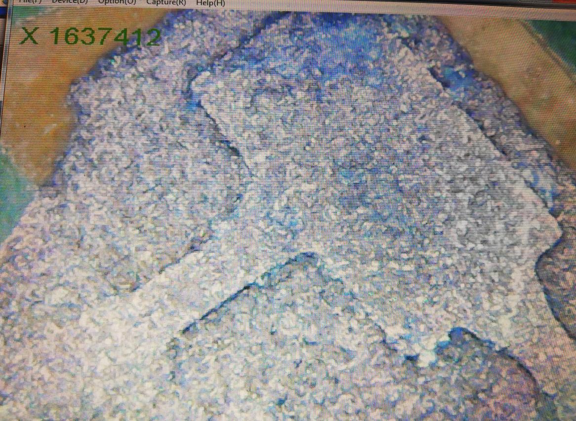
Covered with pencil graphite.
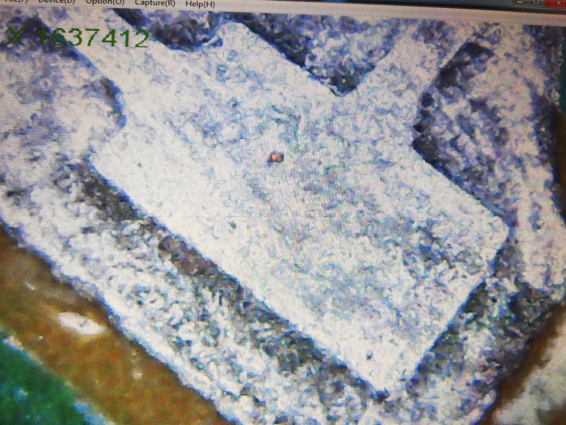
With scratched surface
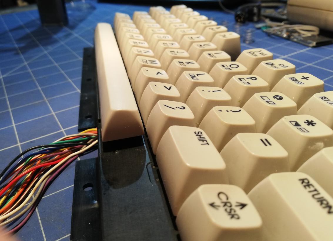
Assembling the keyboard
Next, I assembled a keyboard using brand new keyboard springs. You can get them HERE.
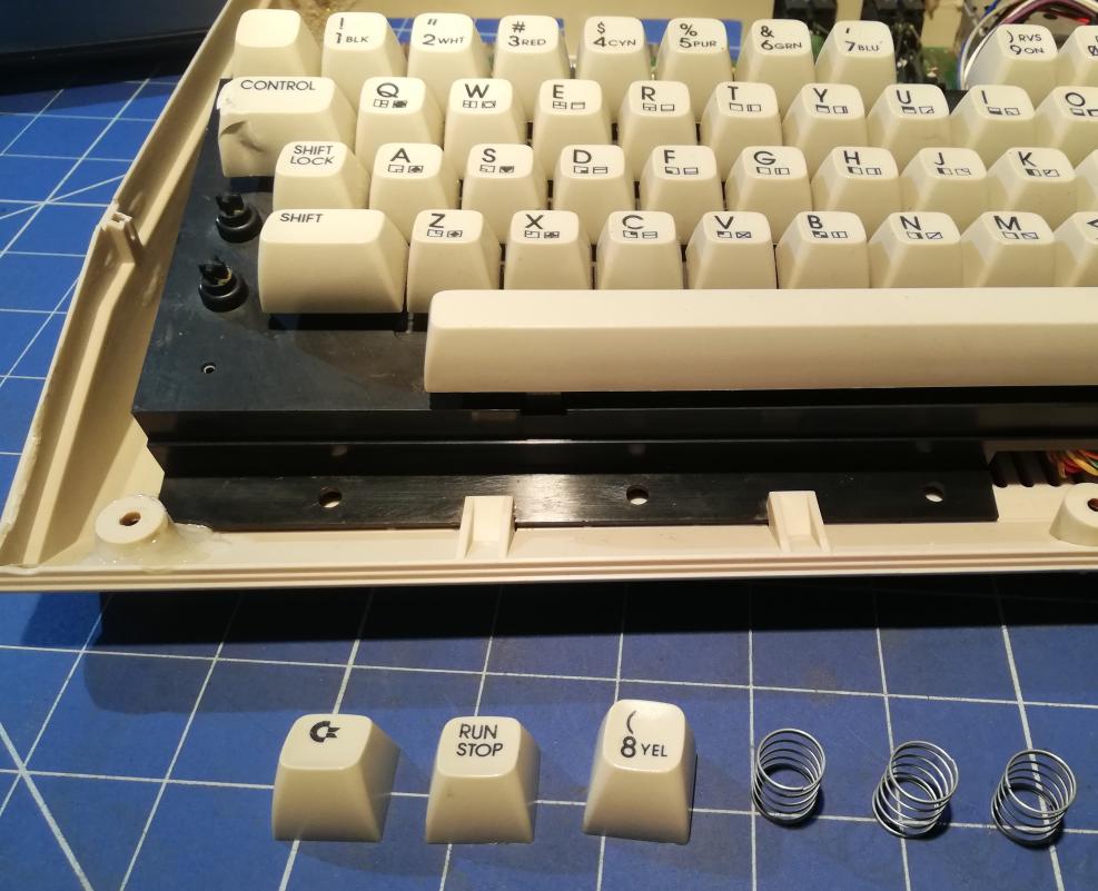
I’ve also found replacement keys for those that were missing. I had to retr0bright them separately to match the whole keyboard. I didn’t have one of the keys so I used a painted dummy keycap.
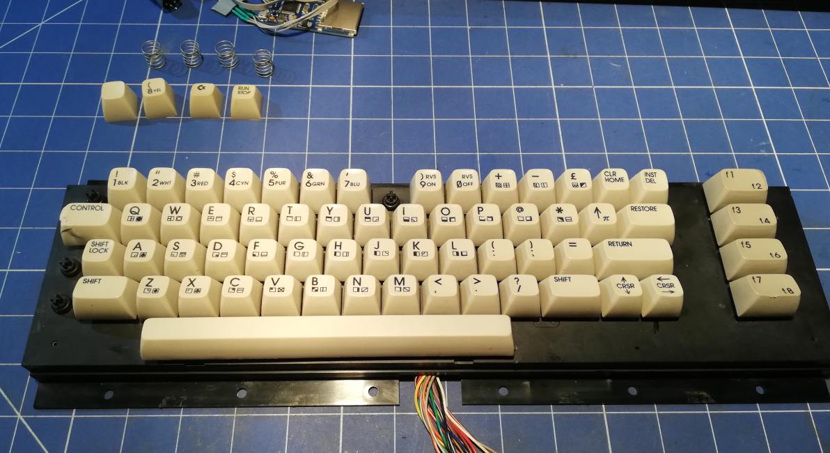
Finally, the last three retr0brighted keycaps were ready for installation. 🙂
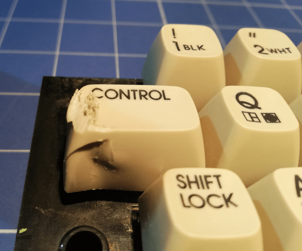
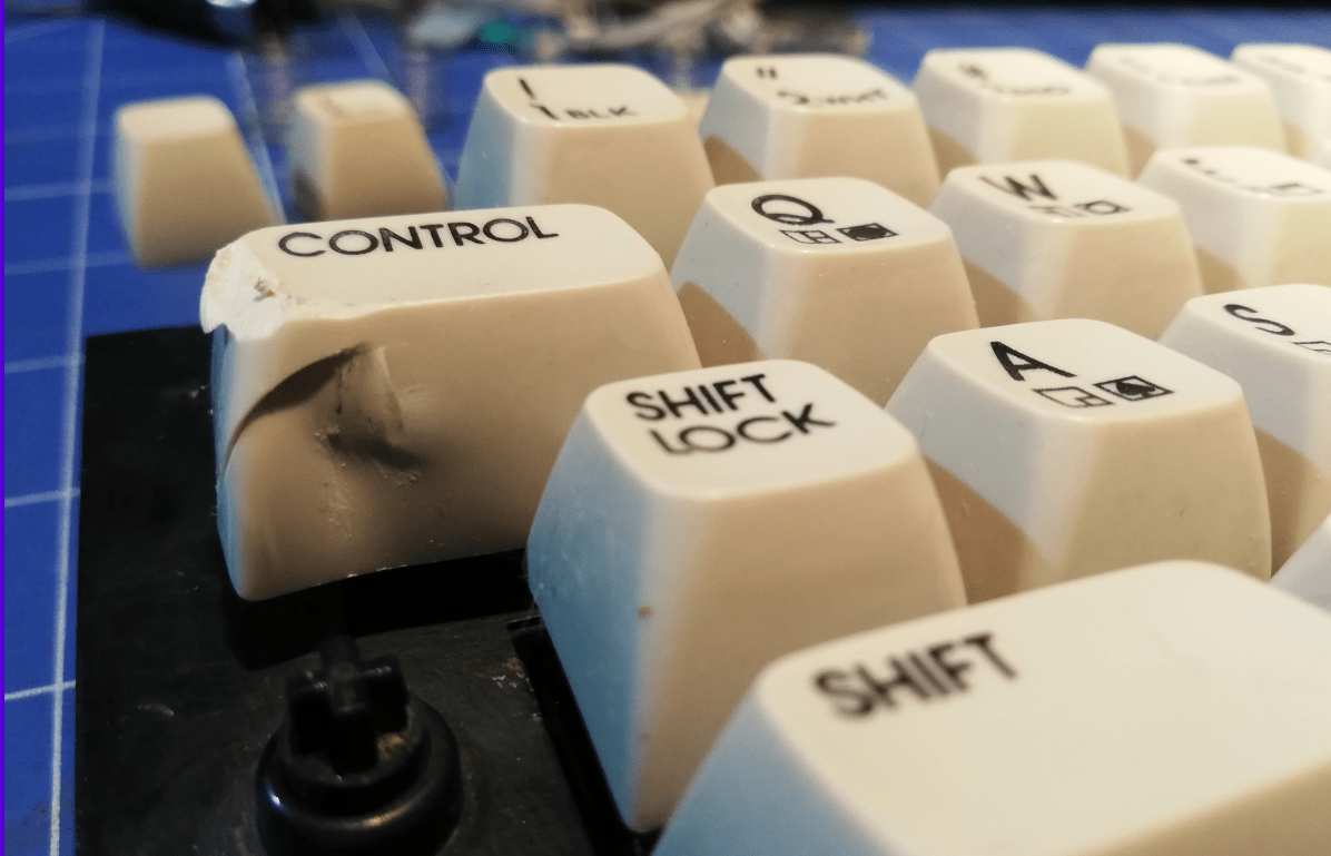
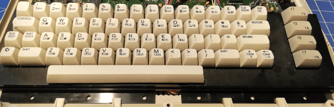
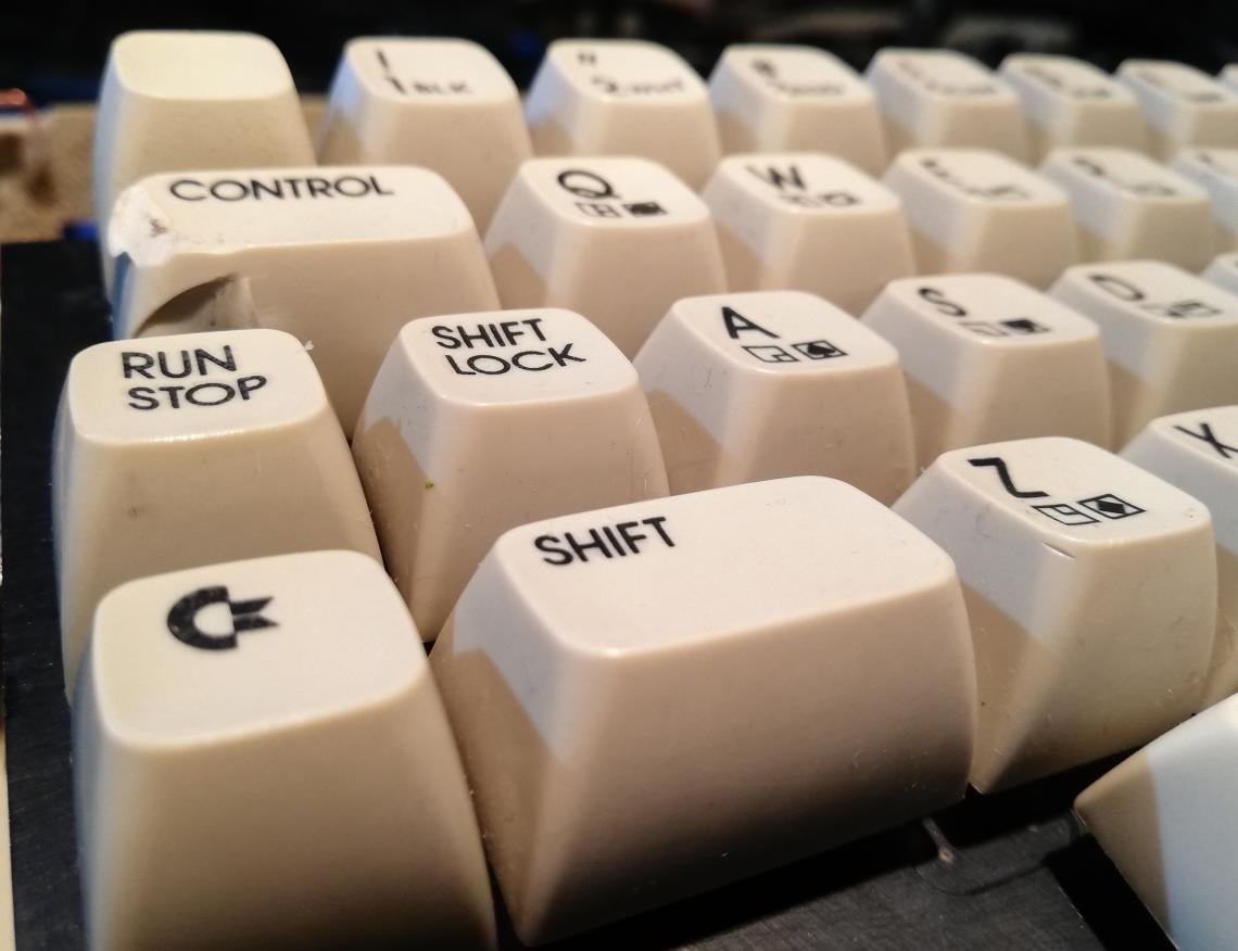
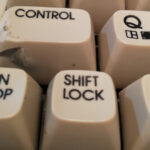
Aaaaand … job is done 😀 I’ve left the CONTROL key intentionally for authenticity purposes 🙂
Ok, enough for this part of extreme refurbishing. In the last part, I will cover case fixing and assembly of the whole unit 🙂
See you soon 😀

OUTRO
If you want to get retro gear or hardware modules, please visit our shop -> https://retrohax.net/shop/
Please support our work by commenting here and on the Facebook page or Twitter
I am looking for more retro computers to repair so feel free to send me a machine that is dead. Moreover! Extreme cases are welcome 🙂

Wow great effort! I love that you’re keeping the mangled CONTROL key and look forward to the next installment.
The Lamers way 😀
OMG! Thanks for giving those old guys second life
Amazing work as always. Thanks for sharing.
Thank you sir 🙂