… or … am I stoned? :>
<intro>

</intro>
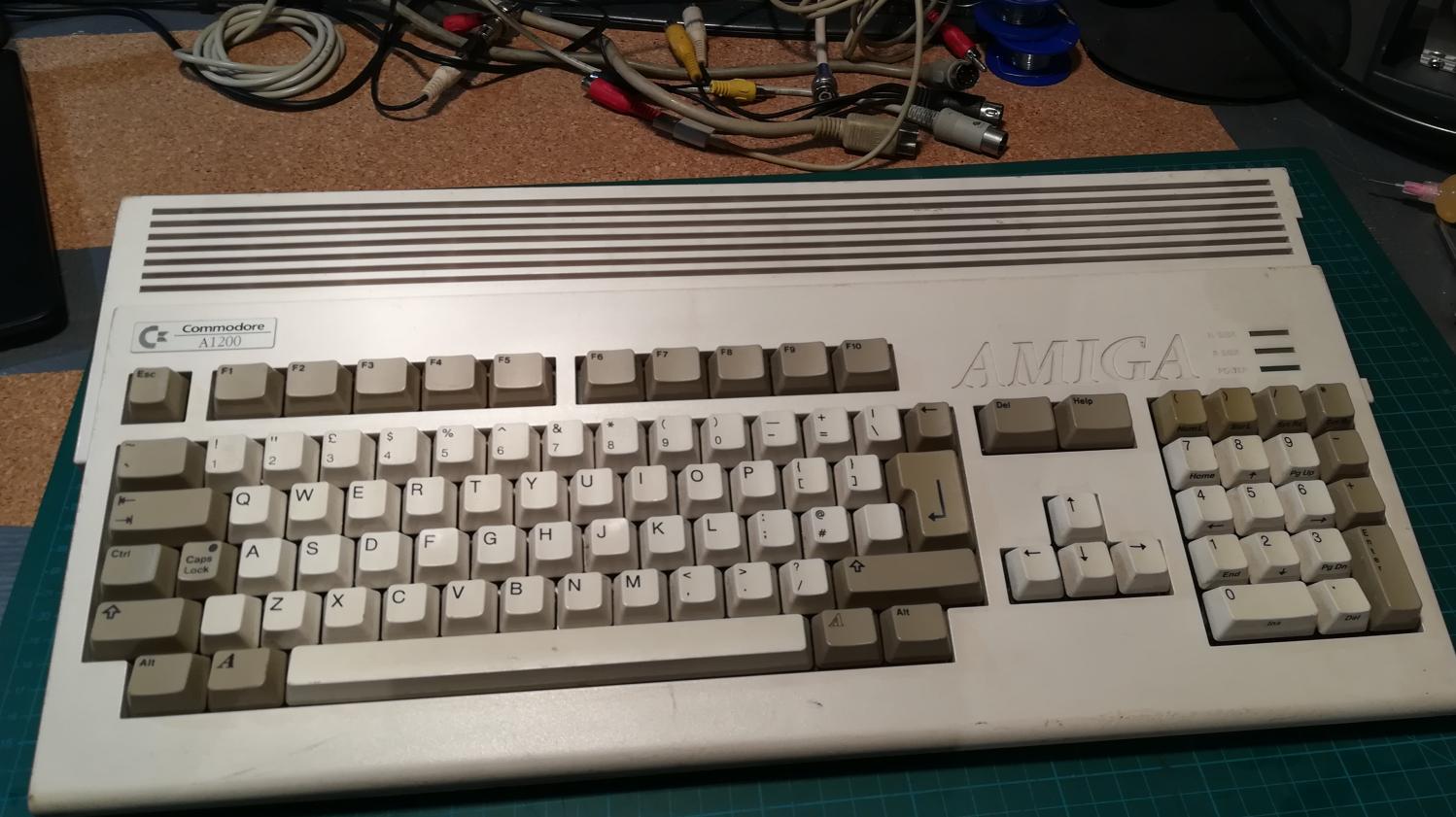
Just another twelve-hundred
Ok, another day another job 🙂
This time it is the Amiga 1200 which is a super cool retro computer sought by a lot of folks nowadays.
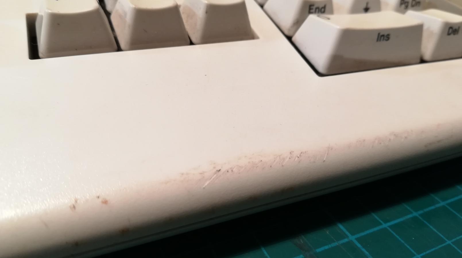
I bought this unit in a non-working state. It was a bit dirty, with some scratches on the case but as it later turned out, required a bit more work inside 🙂
Decrunching …
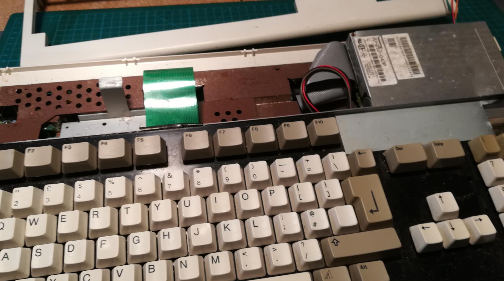
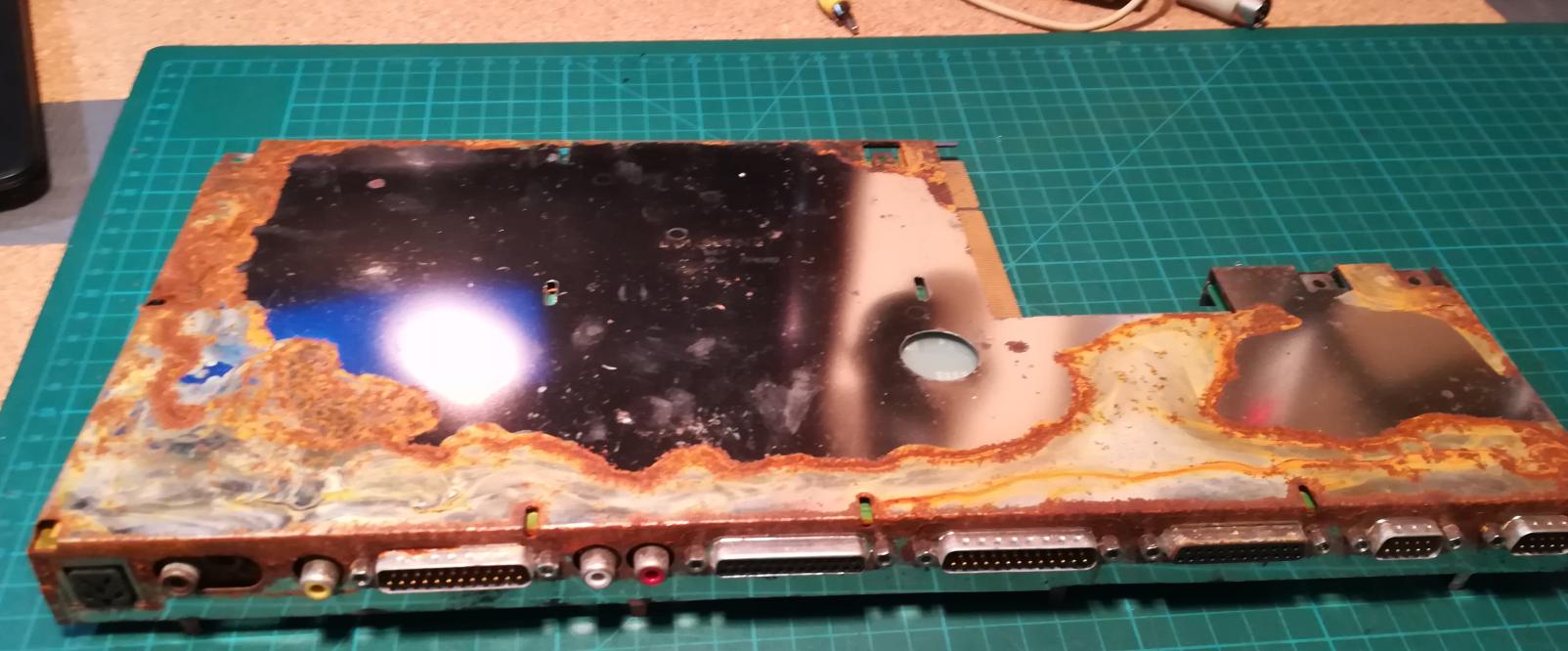
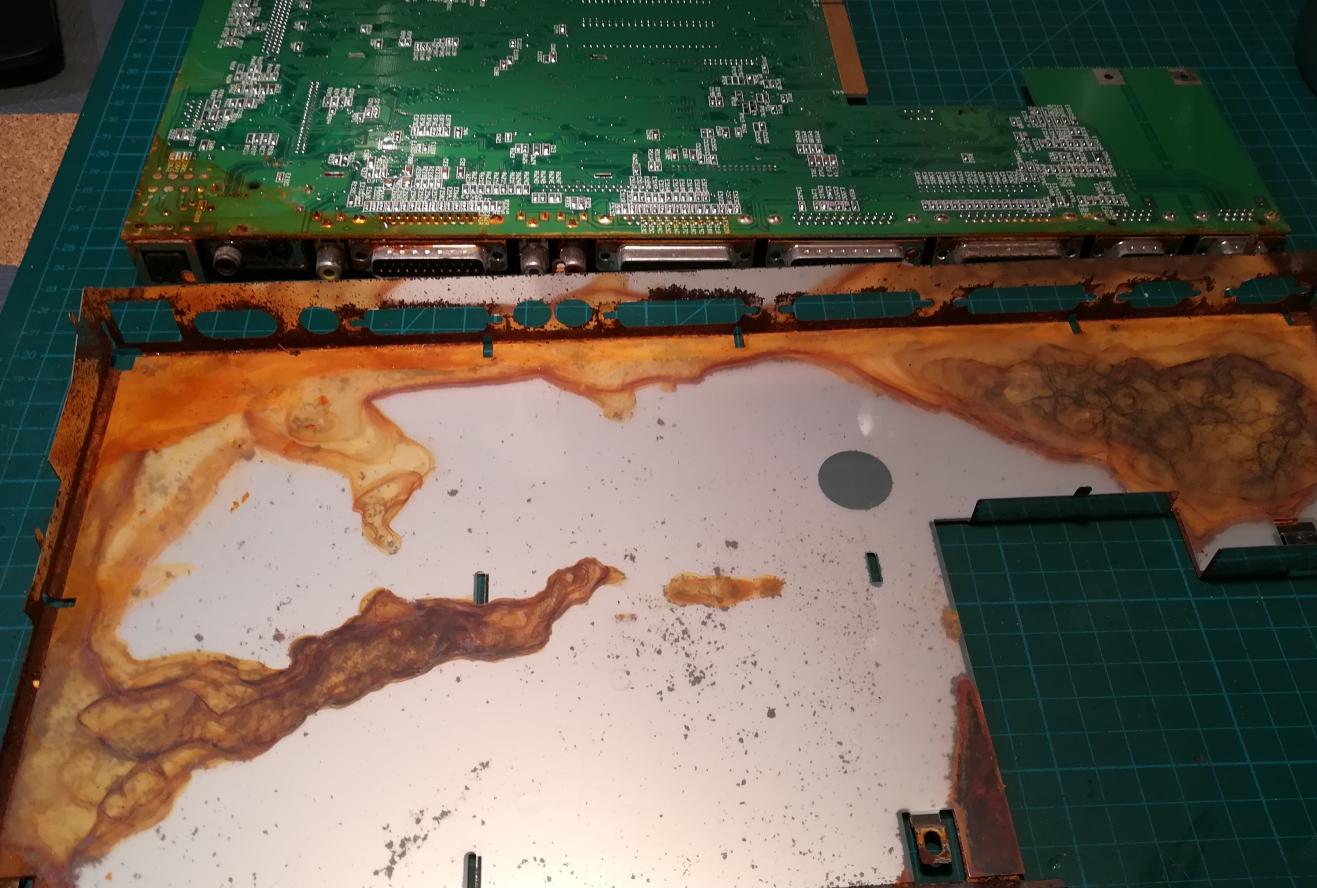
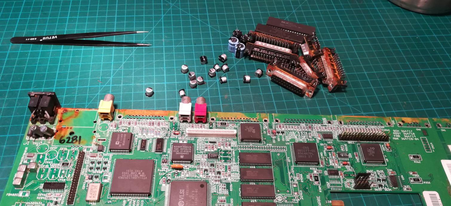
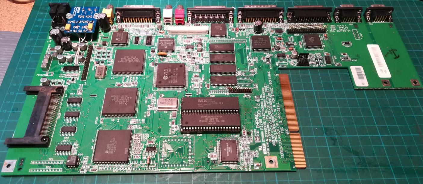
Disassembly followed quickly.
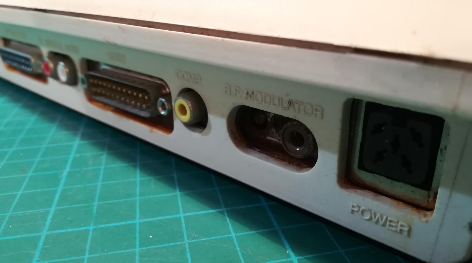
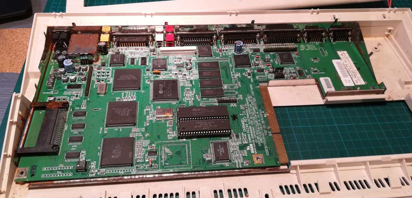
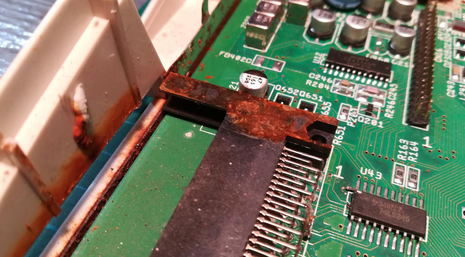
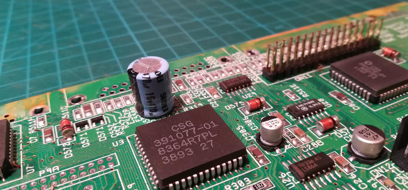
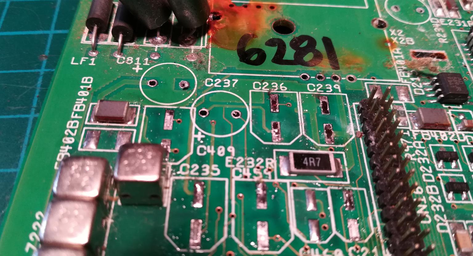
It slowly started to become obvious that this poor Amiga was heavily corroded.
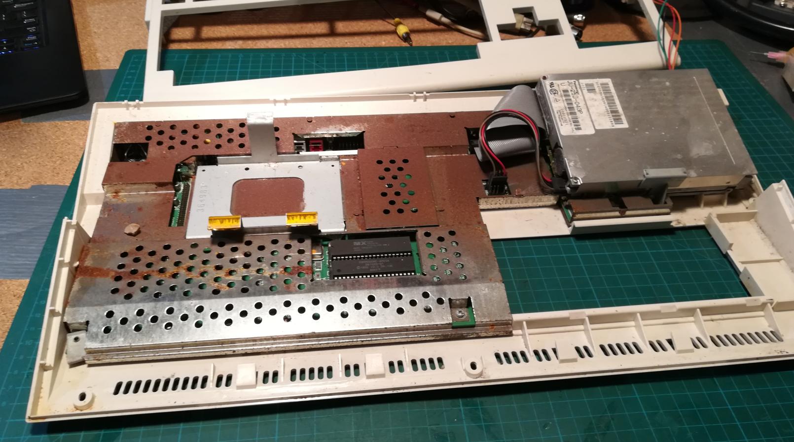
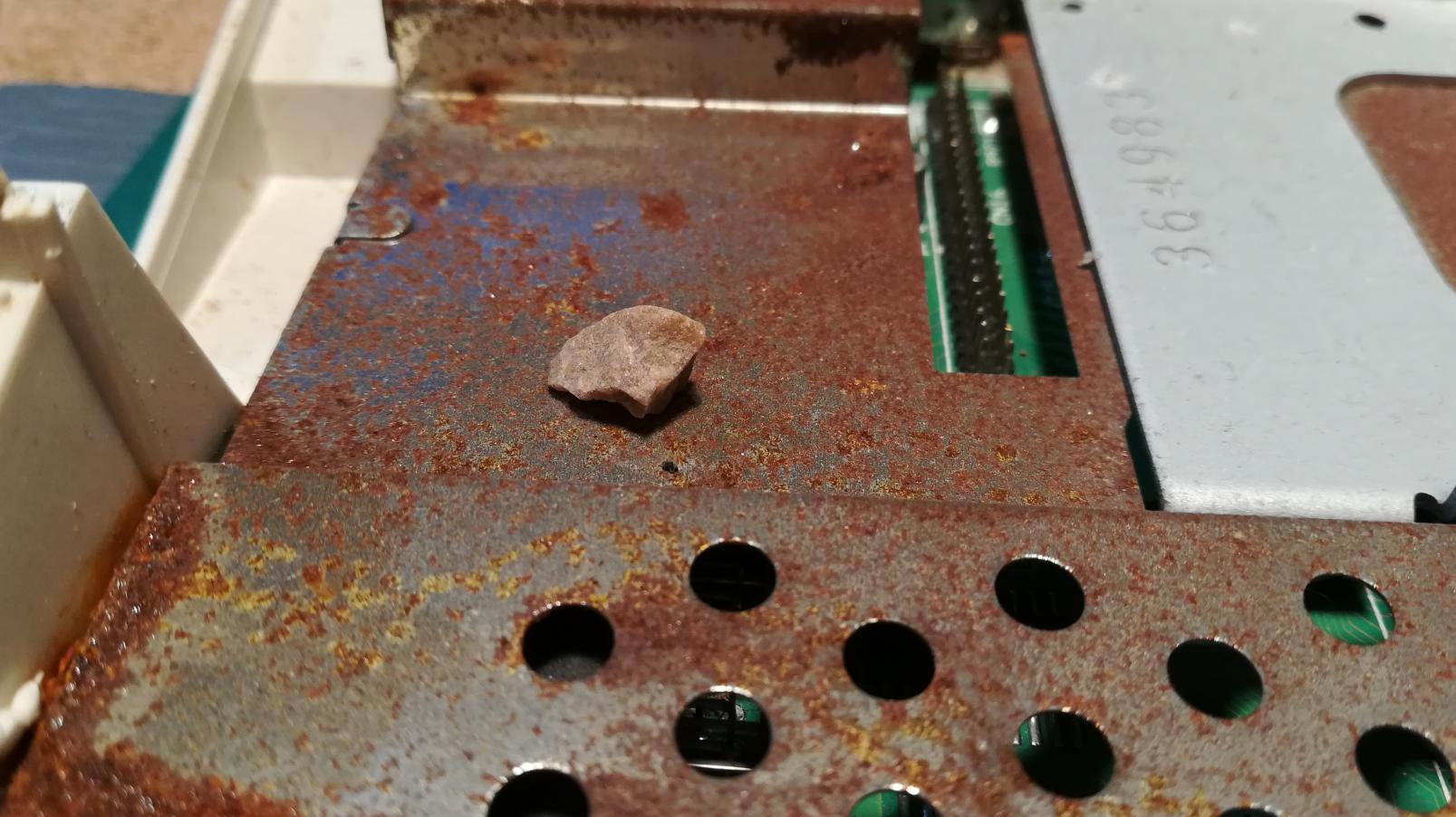
So far, I saw bugs, fungi, leaves, spiders, and other weird things inside computers, but this time it was a bit different lol.
I was STONED 😀
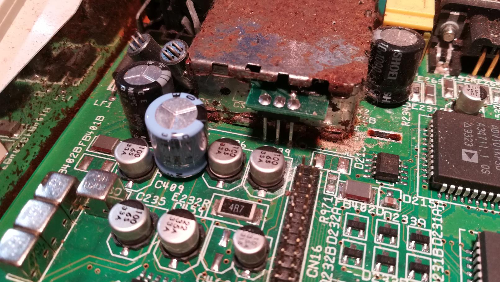
Looks like someone tried to fix it before me 🙂
Fixing electronics
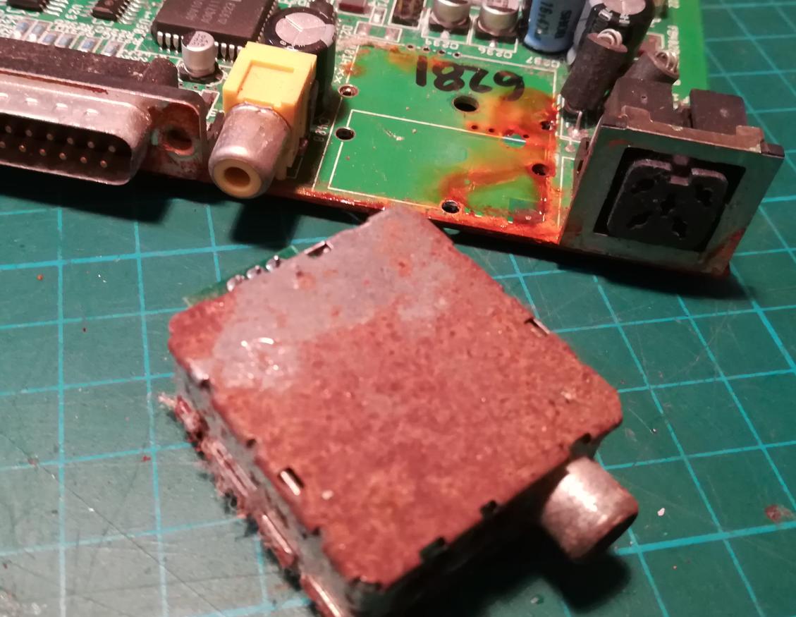
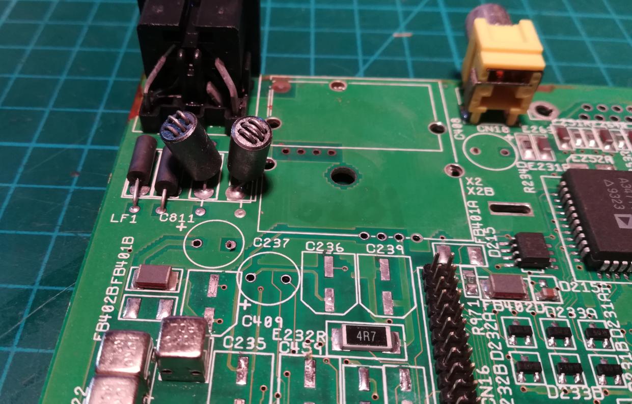
To progress with this repair, I had to remove all ports, and RF modulators, and replace electrolytic capacitors.
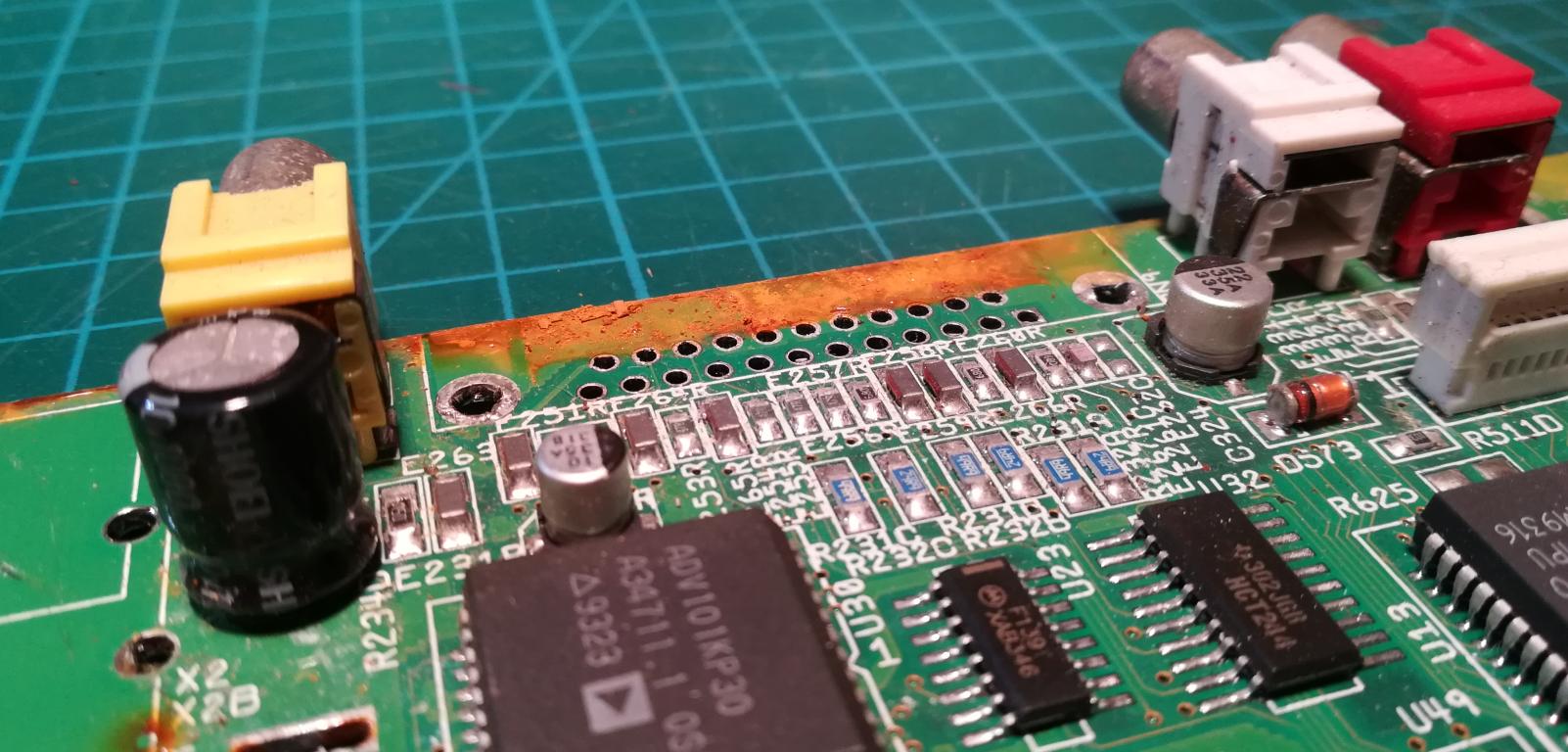
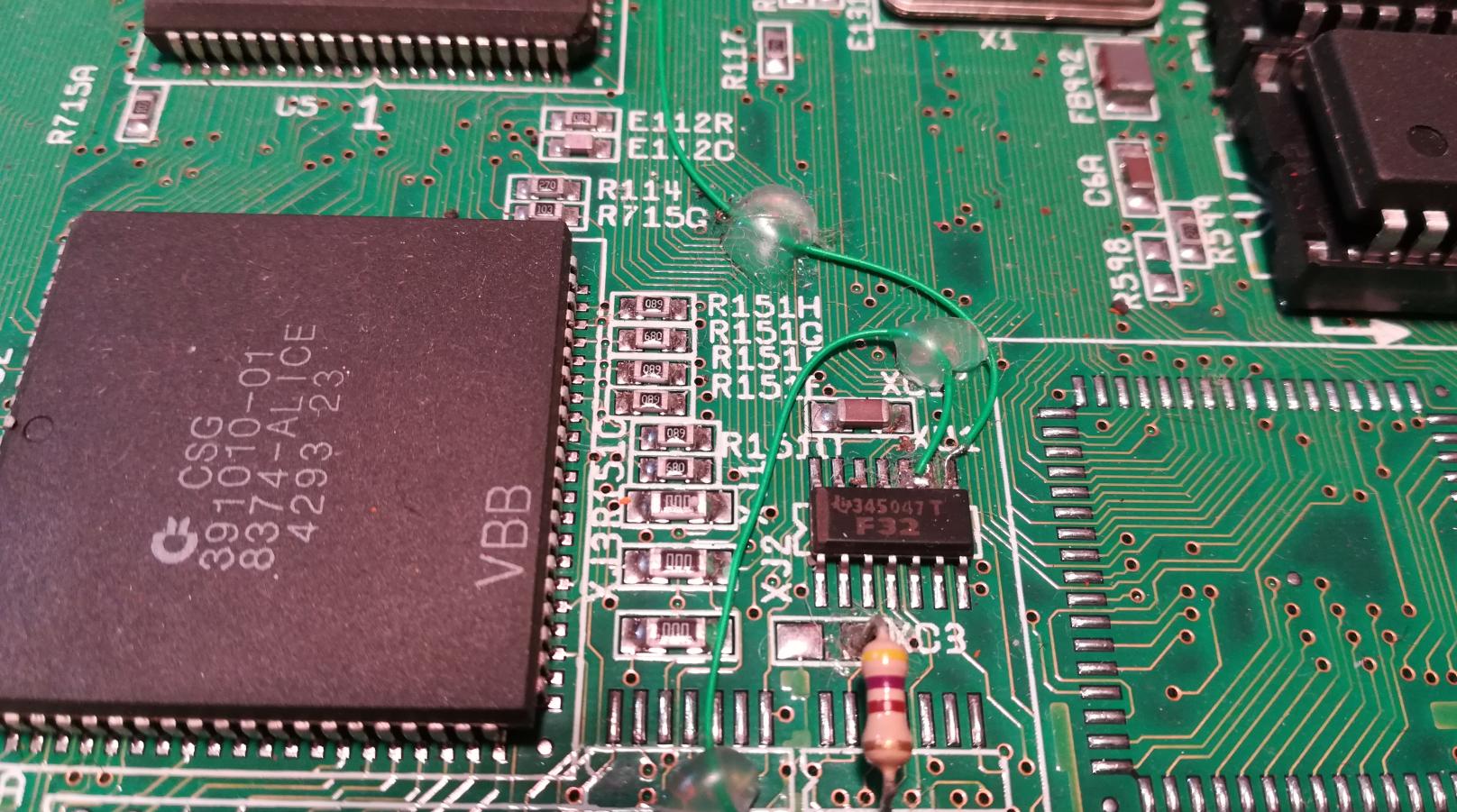
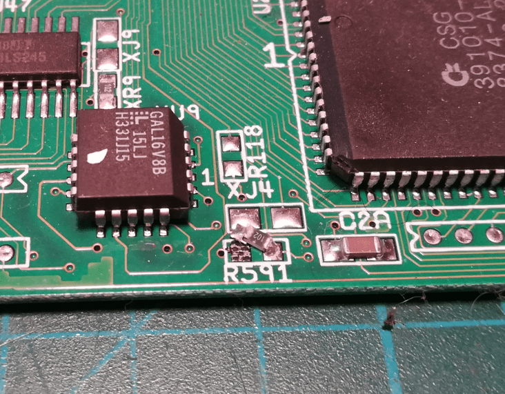
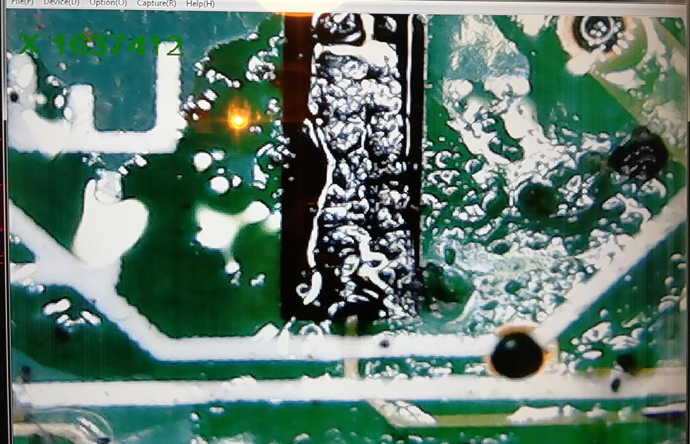
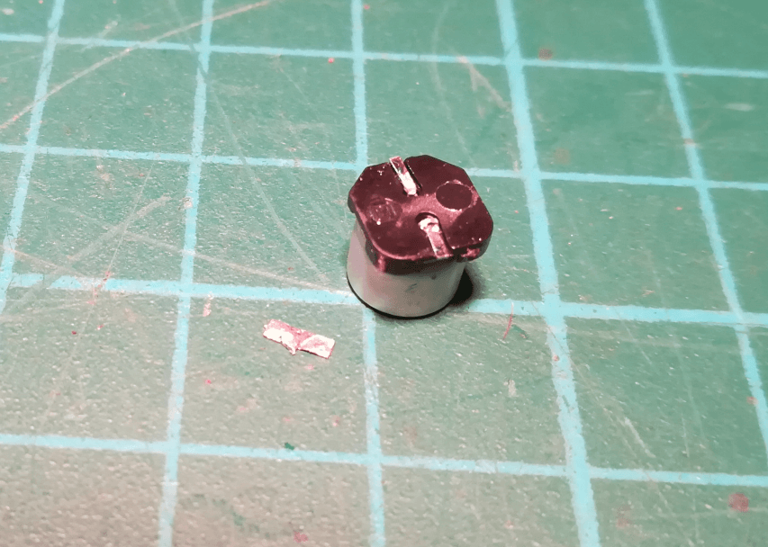
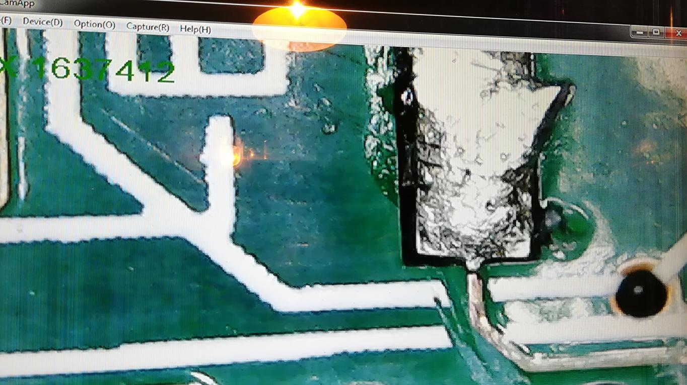
Some SMD pads on a PCB didn’t make it because of the corrosion 🙁
I’ve managed to fix that pad with a drop of resin. Once the resin cured, I could gently connect this pad to a trace with a bit of solder.
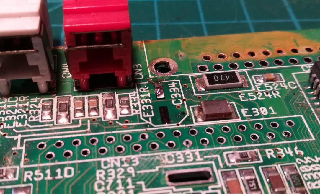
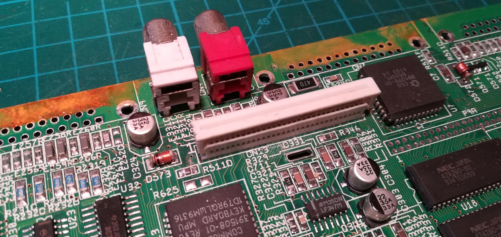
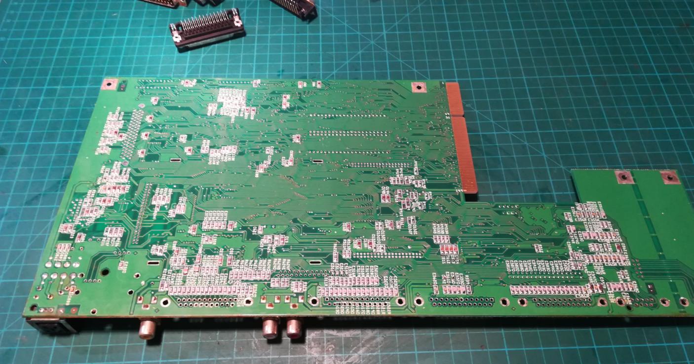
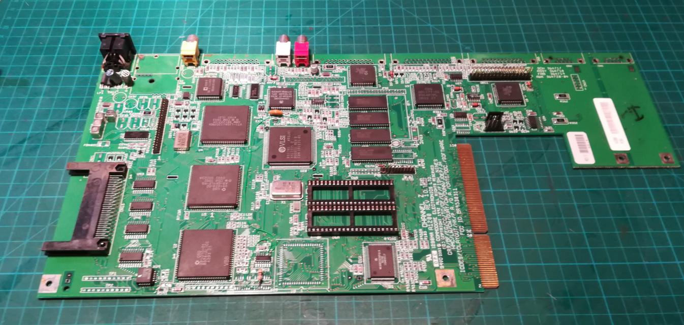
Finally, I could clean the whole board of dust, flux residue, and other gunk. Below, are some pictures after cleaning.
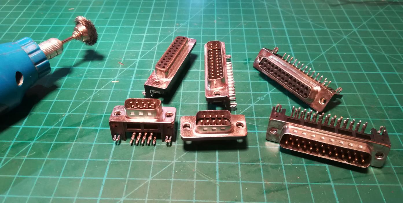
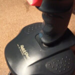
Next, I cleaned all ports with a steel brush on a rotary tool.
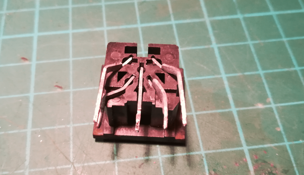
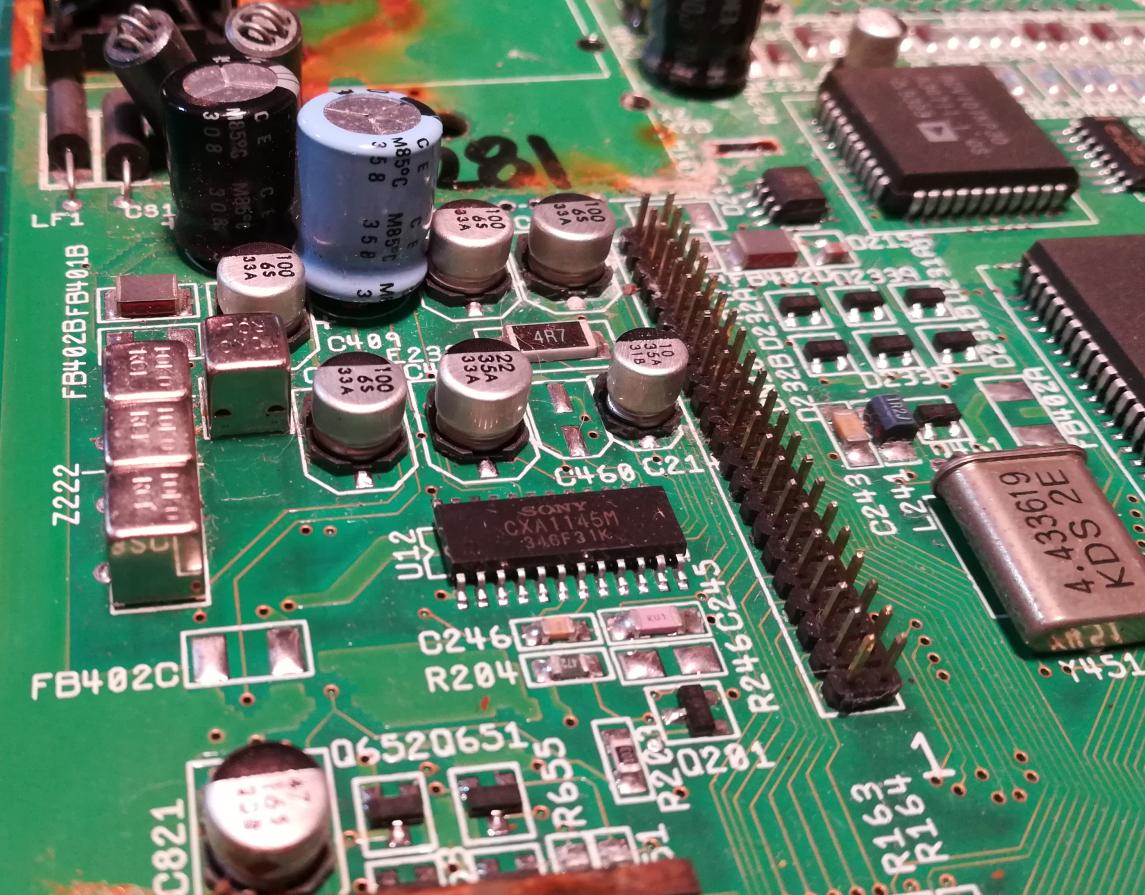
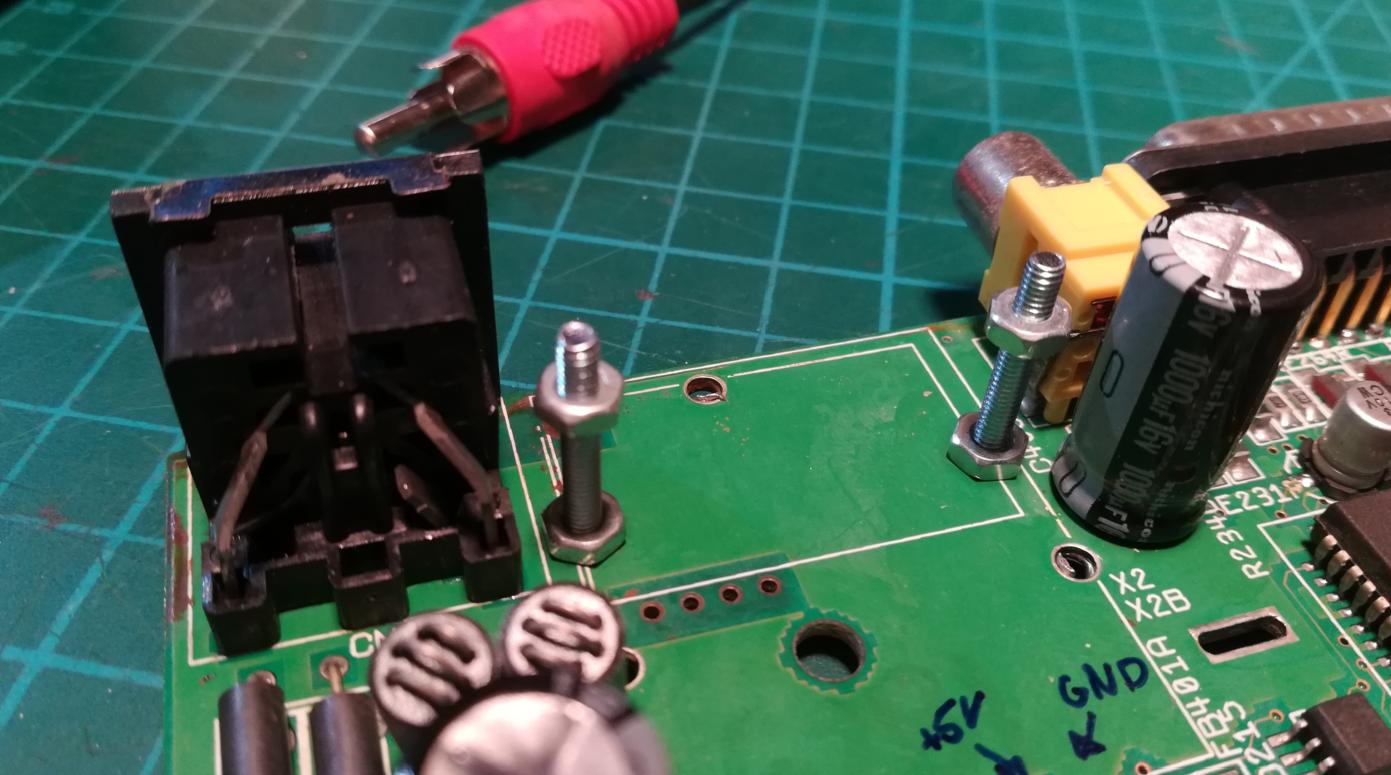
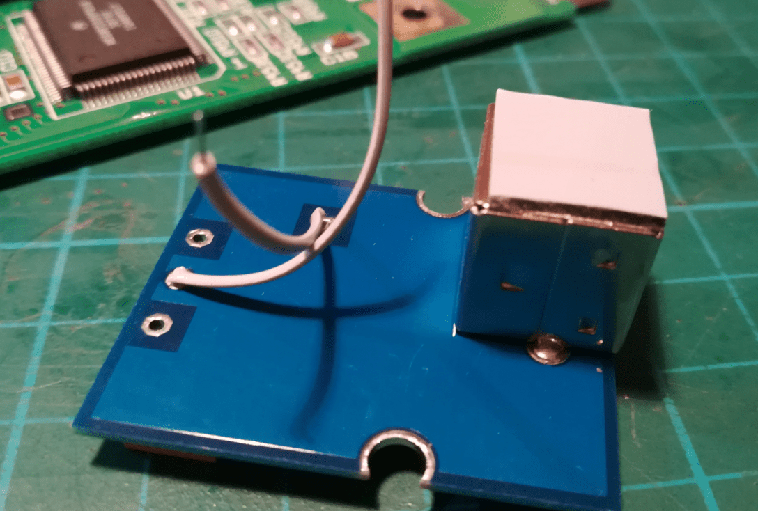
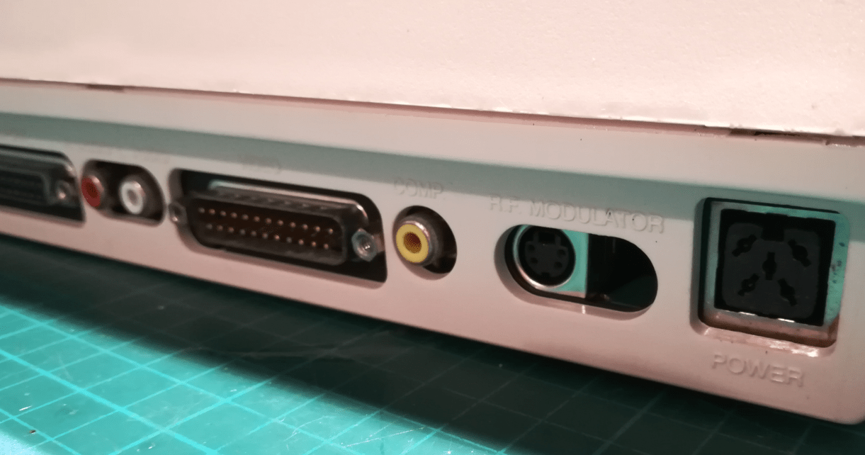
I already knew that I will be replacing the RF modulator with the S-Video module. It outputs way better video than Color Composite and is often a cool alternative if you have a monitor or TV with an S-Video input.
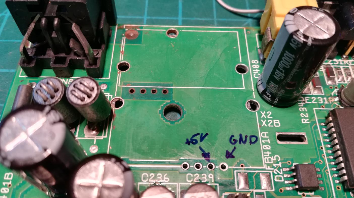
To install it, I usually use two M3 screws. Connecting it is fairly straightforward as it takes 5V and GND from RF modulator vias. It also needs LUMA and CHROMA signals from CXA1145.
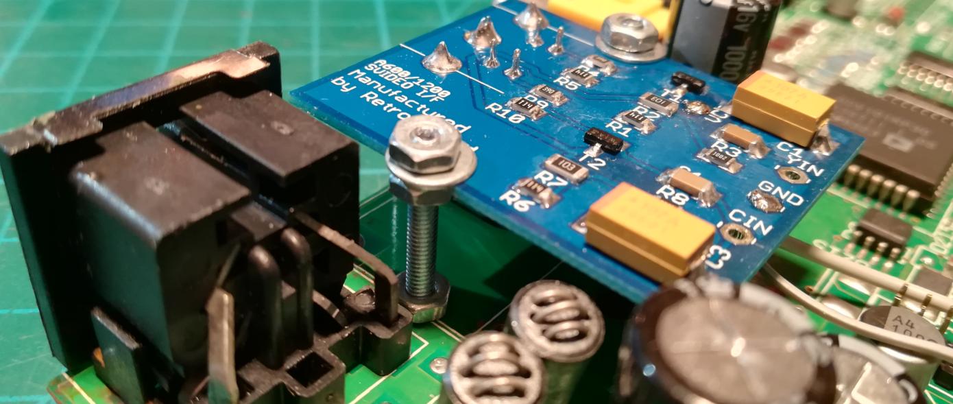
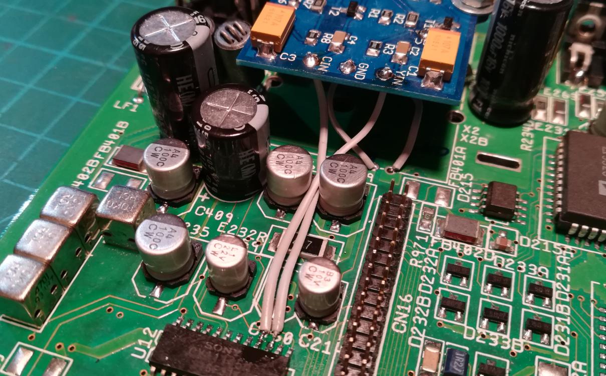
Fully recapped motherboard S-video mod and ports in place 🙂
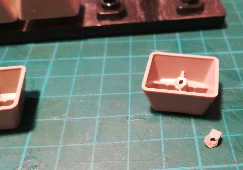
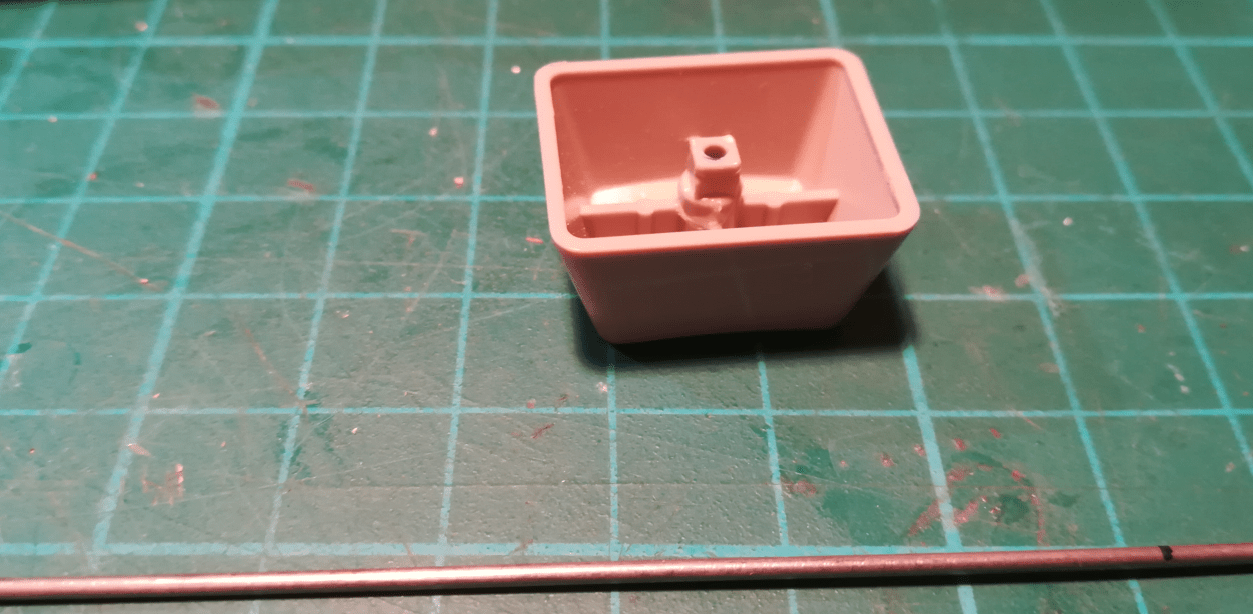
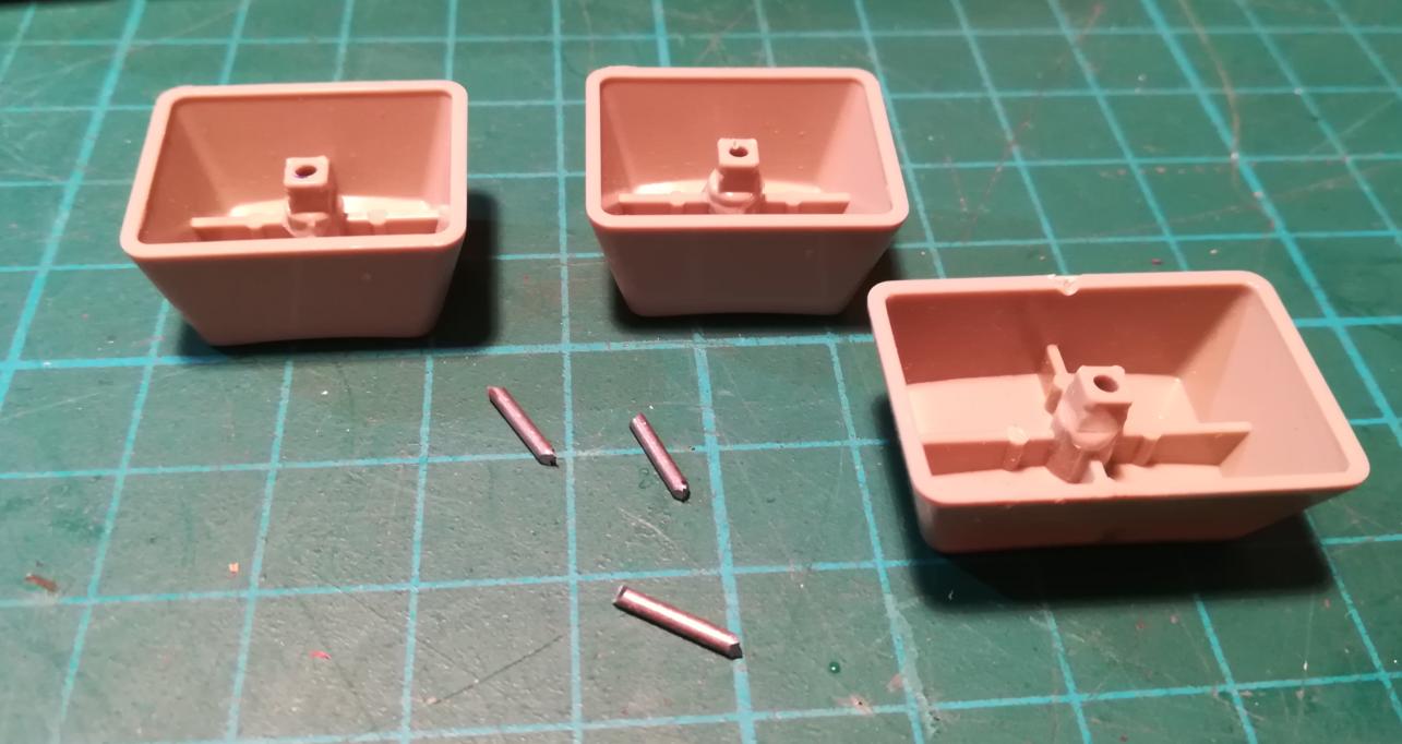
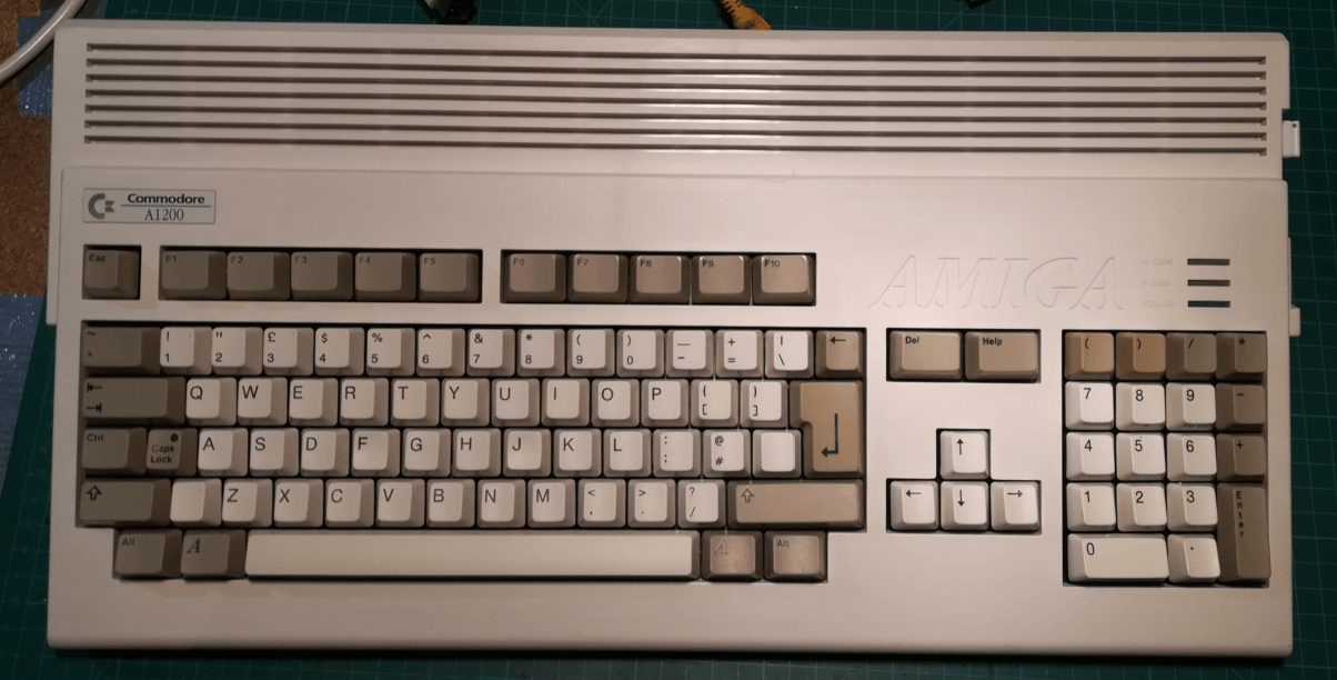
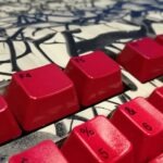
Keyboard
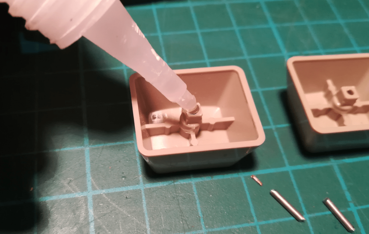
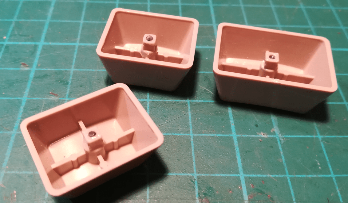
A few of the keycaps had broken studs. I’ve gently removed studs that were stuck in plungers and bound them to corresponding keys by inserting a steel wire and using cyano-acrylic glue to hold them in place.
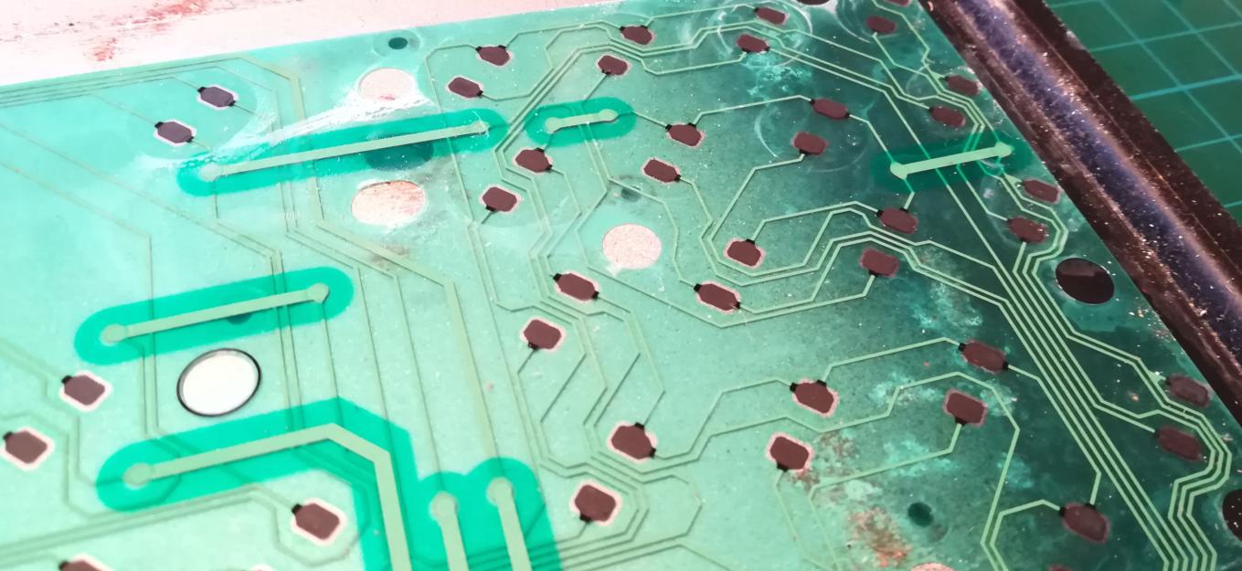
The keyboard membrane was damaged and a lot of pads worn out so I’ve decided to replace it with a brand new keyboard membrane.
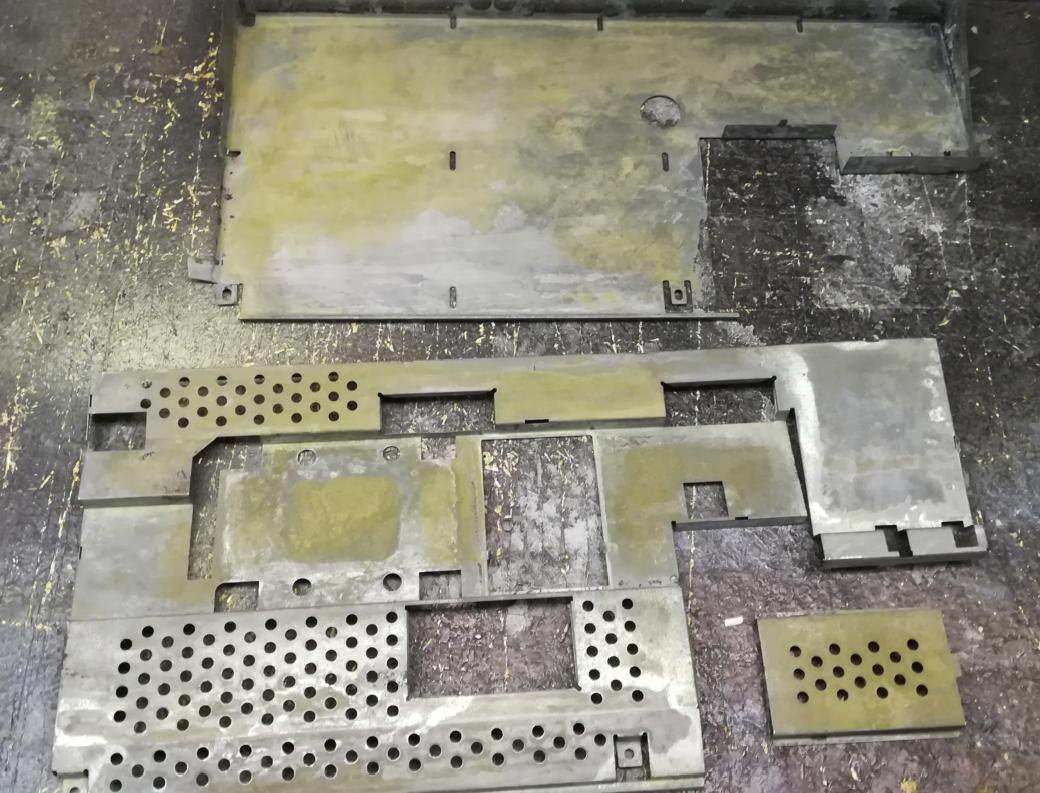
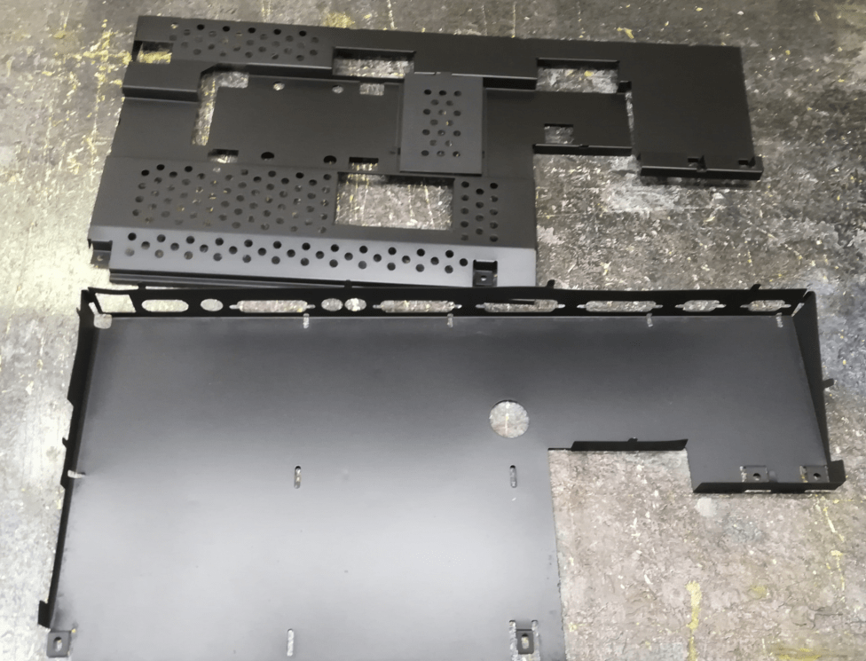
Metal shielding
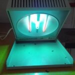
I had to get rid of all rust that covered the metal shielding. I’ve used an electrolytic method that I’ve described already in one of my previous posts. Below is a video with rust being removed from A500 shielding.
It worked like a charm so I’ve spray-painted it.
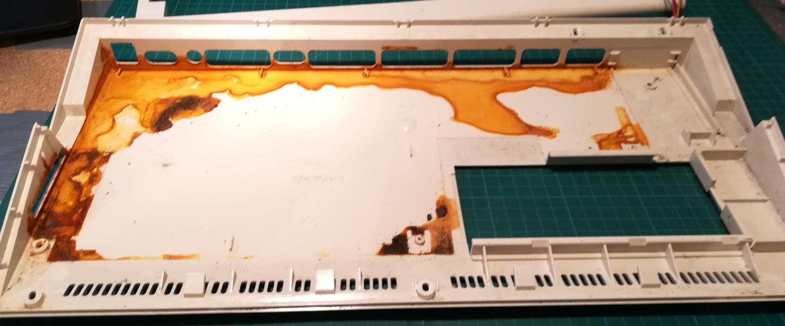
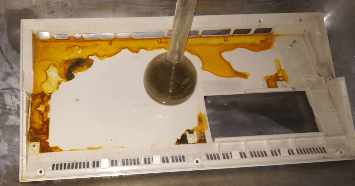
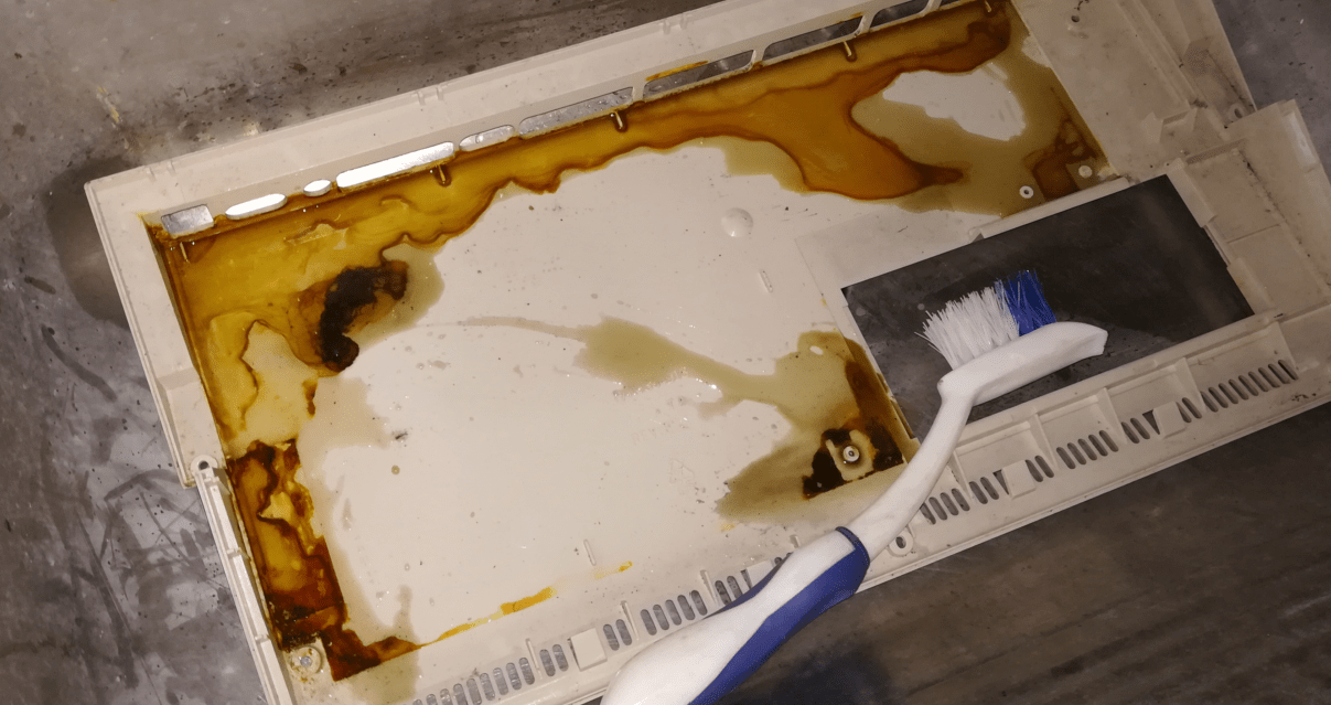
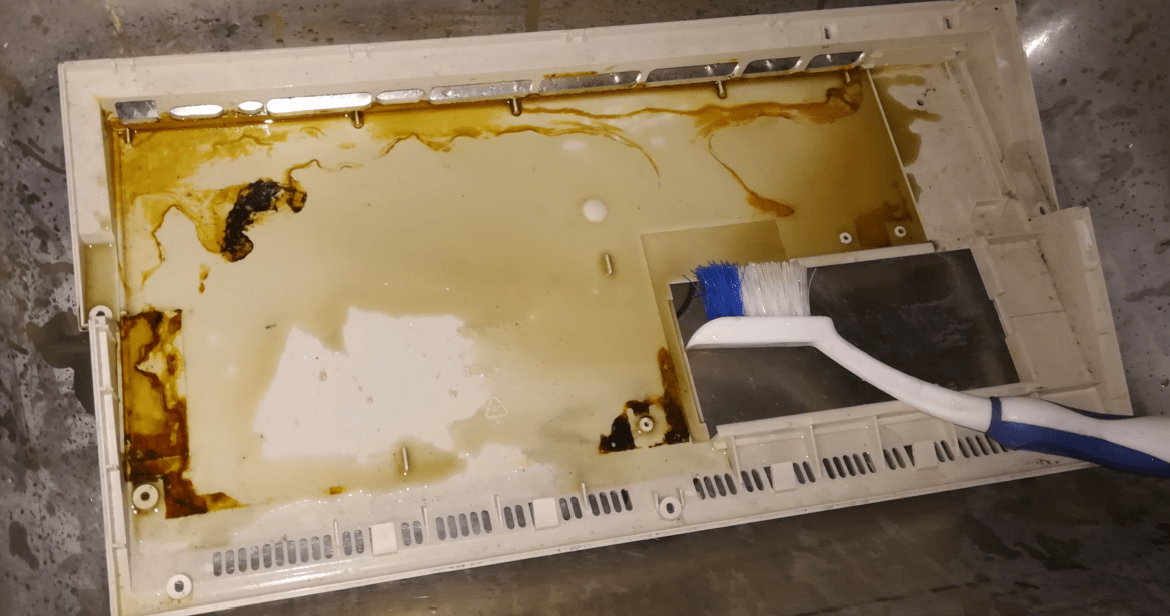
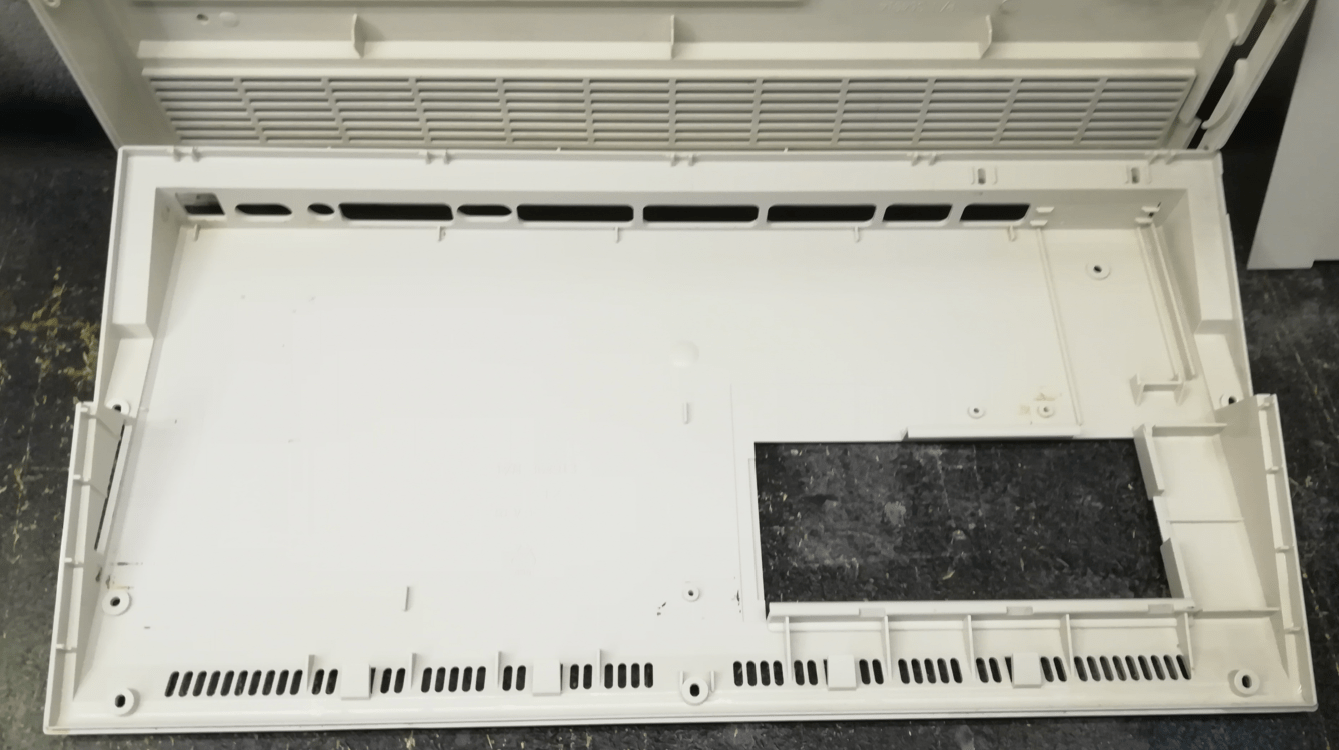
Case
Finally, I had to clean all of the rust from a plastic case. To do it, I’ve covered all stains with Phosphoric Acid which nicely binds to Iron Oxide.
Gotek and putting it all together
Finally, I was ready to assemble it. I’ve replaced the original 3.5″ floppy drive with a GOTEK interface that was installed on a 3D printed bracket.
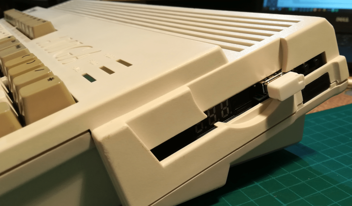
That’s it! 🙂

Outro
If you want to get retro gear or hardware modules, please visit our shop -> https://retrohax.net/shop/
Please support our work by commenting here and on our Facebook and Twitter pages.
If you want to donate a dead computer then drop me an email. Extreme cases are welcome ?


two questions – 1) what does it take to make an A1200 work for USA / Power & 2) work for US NTSC Video?
Since A1200 uses an external PSU, you only need an Amiga PSU released for the US market – 110V/60Hz.
Regarding PAL/NTSC, if I remember correctly, it can be set in the early boot menu.