…or is mah laser useful sometimes?
Intro

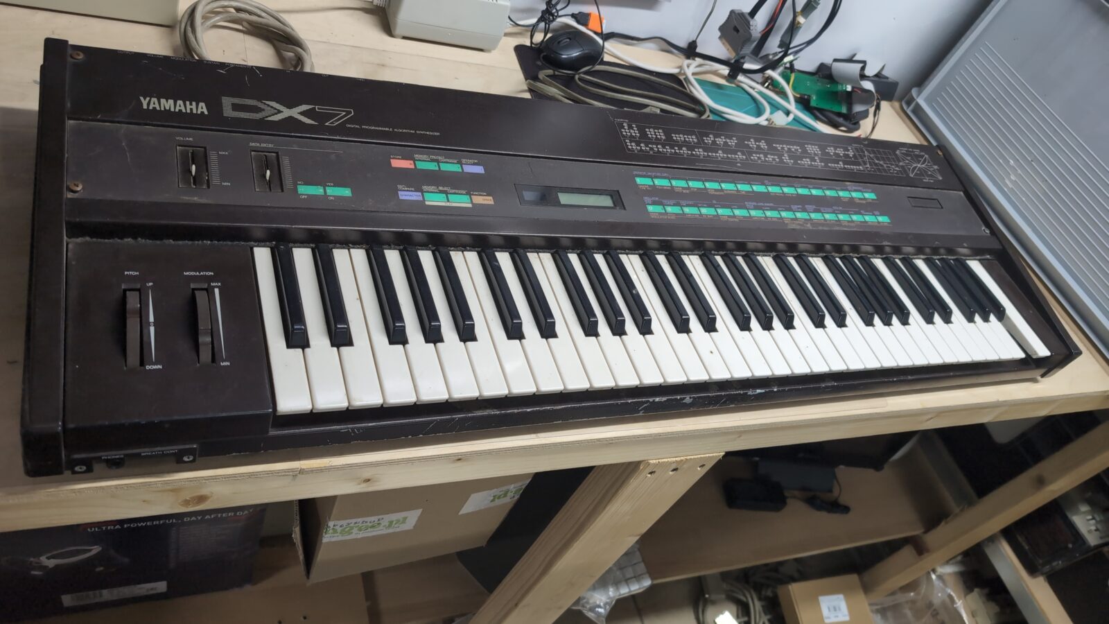
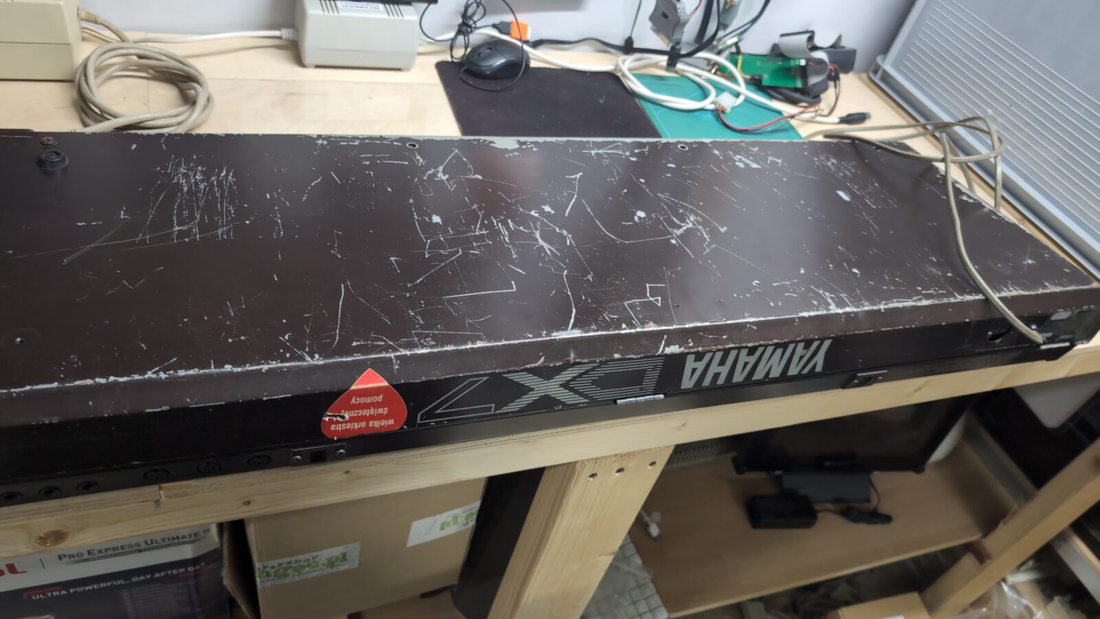
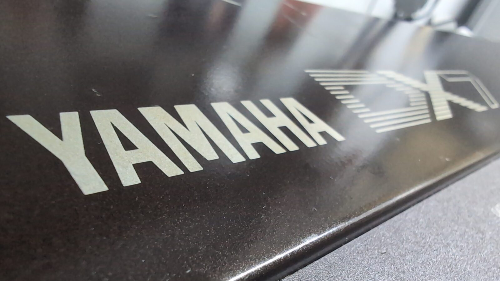
Ohh yeah, Yaaaamaaaahaaaaaaa…..
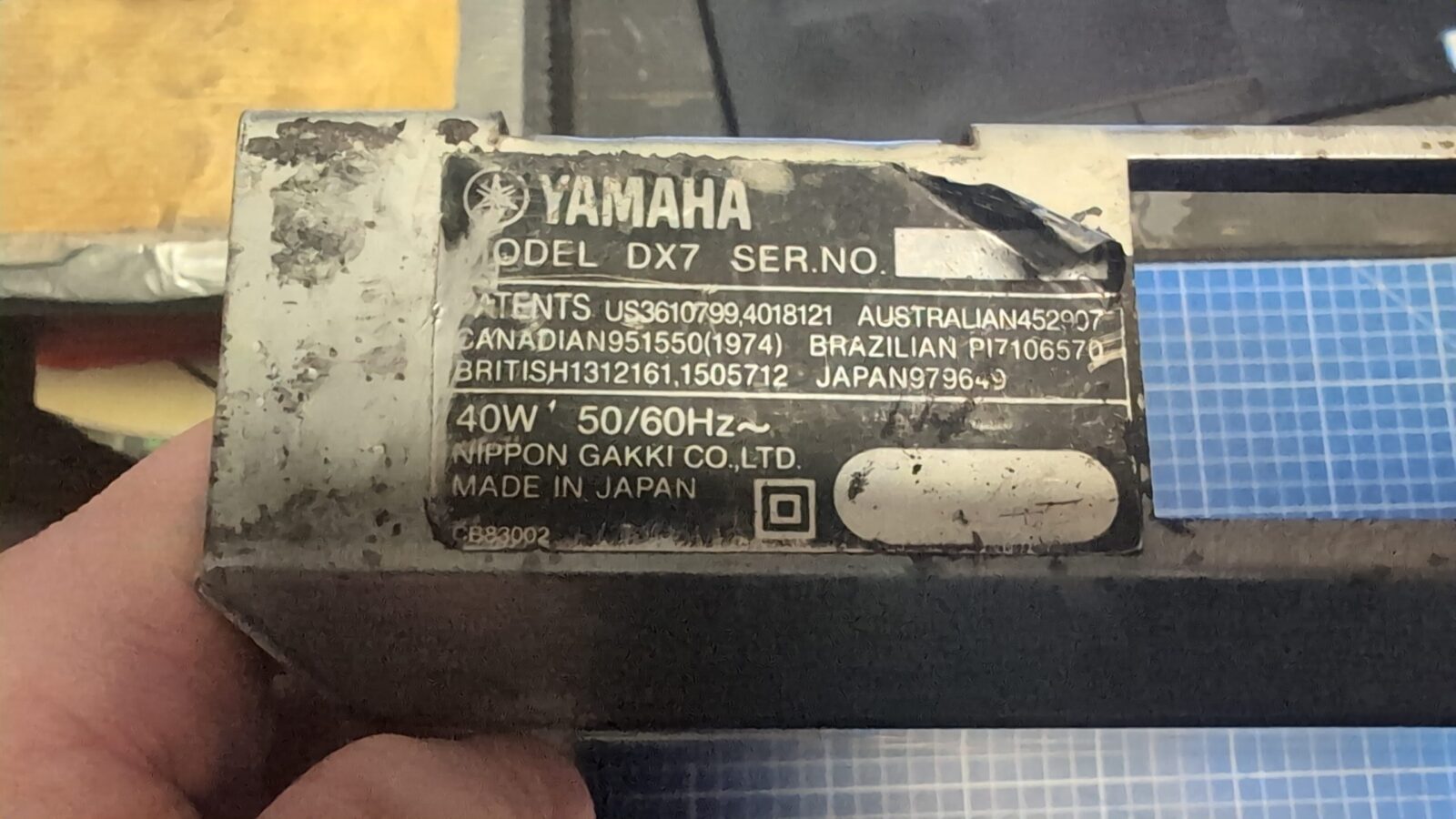
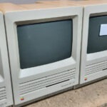
Some time ago, I was fixing backup machines for the Xenium demoscene party, and arabek/Xenium (who delivered those machines) asked me if I could sort out his own classic Yamaha DX-7 synthesizer. The original problem with it was a broken PSU voltage switcher. It was literally broken.
Initially, I was like, hmmm, I’ve never worked on a synthesizer like that, but once I saw it, I was like … hell yeah, let’s do this.
That was a good decision after all, and below you can see why 😀
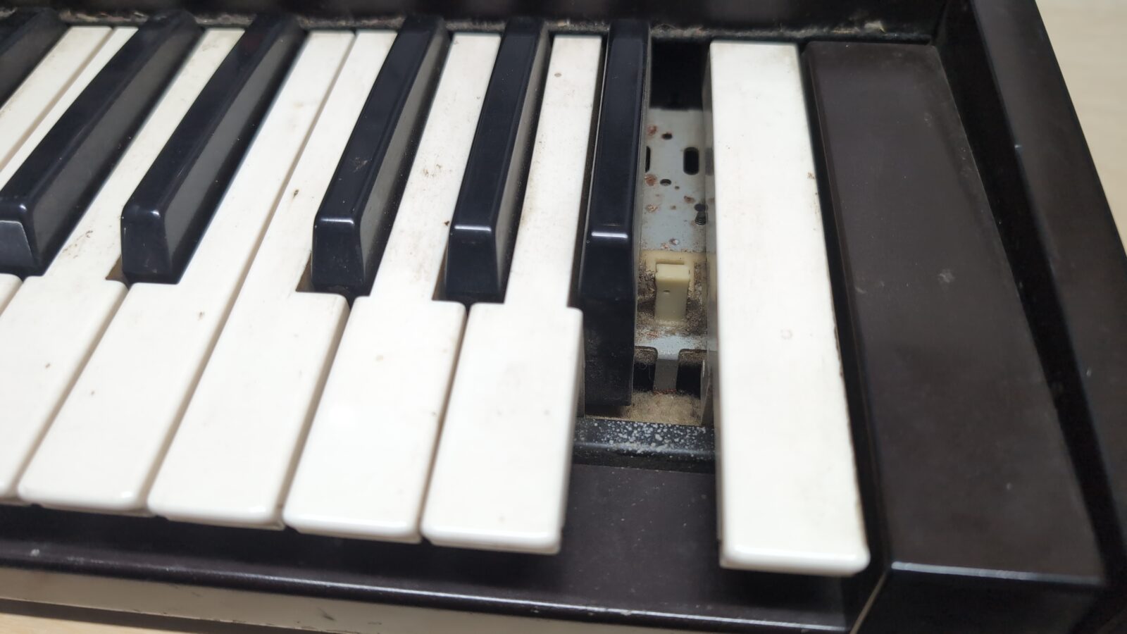
Missing key
Missing handles
Broken voltage selector
Tragic overall shape
After seeing all the above, I wouldn’t be myself if the job stopped at fixing the voltage switch 😀

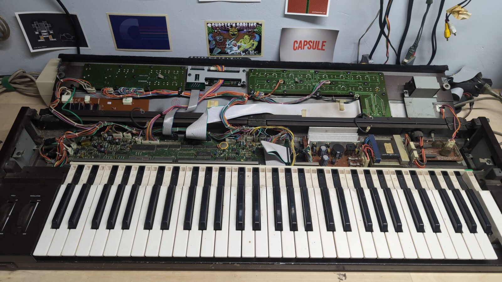
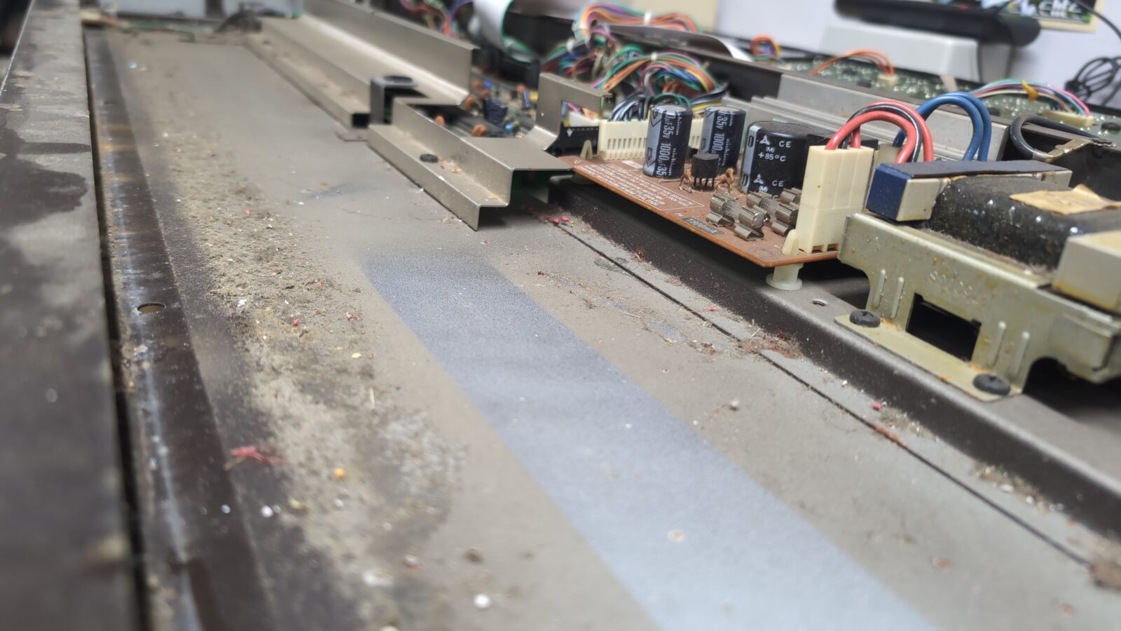
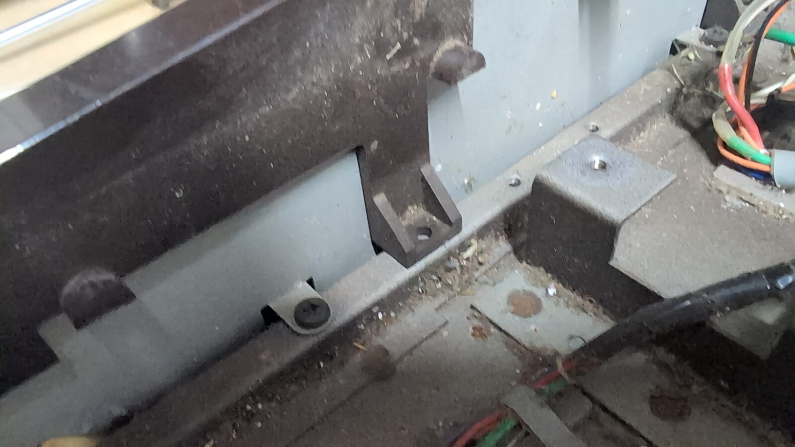
Further disassembly and keyboard restoration
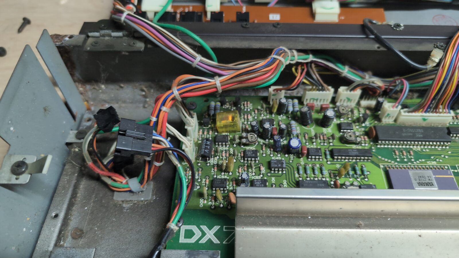
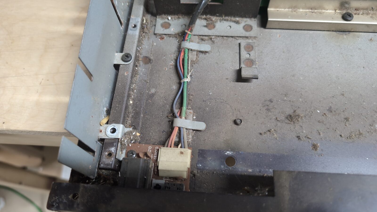
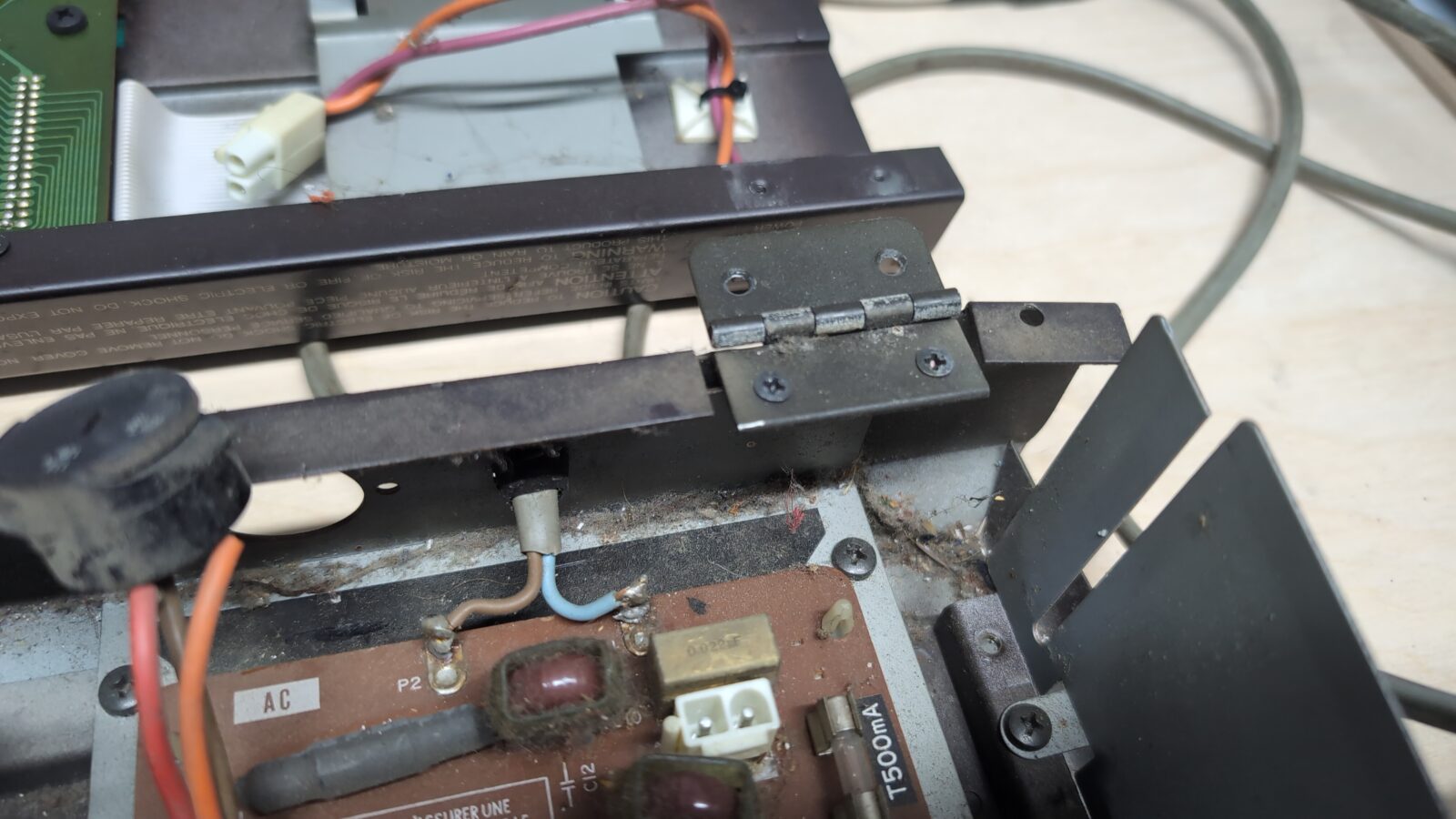
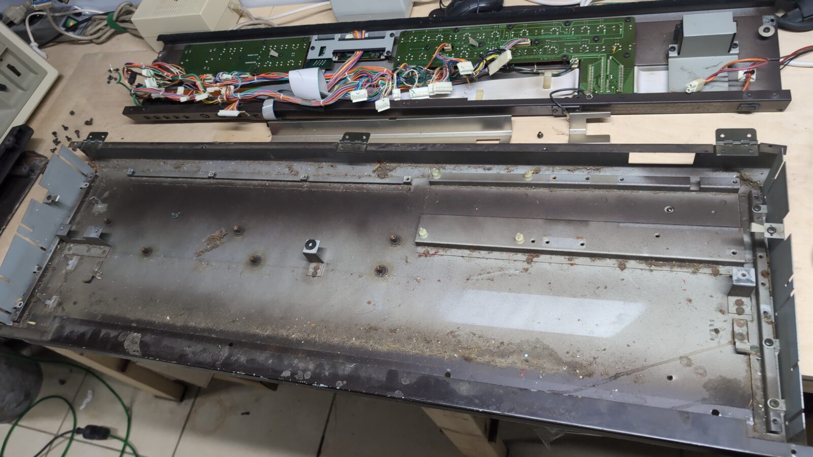
I took some pictures of the wiring so as not to mess things up while assembling it back.
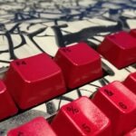
Next, I’ve started with keyboard disassembly and cleaning as it REALLY needed it.
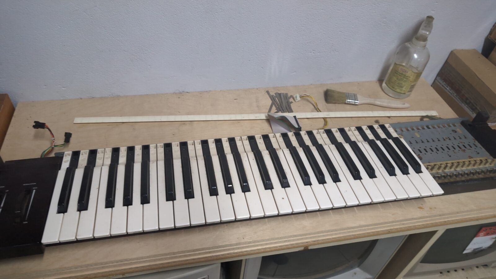
All keys were cleaned with some detergents after being removed. Slightly tedious job 😀
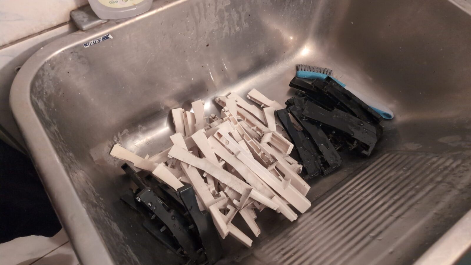
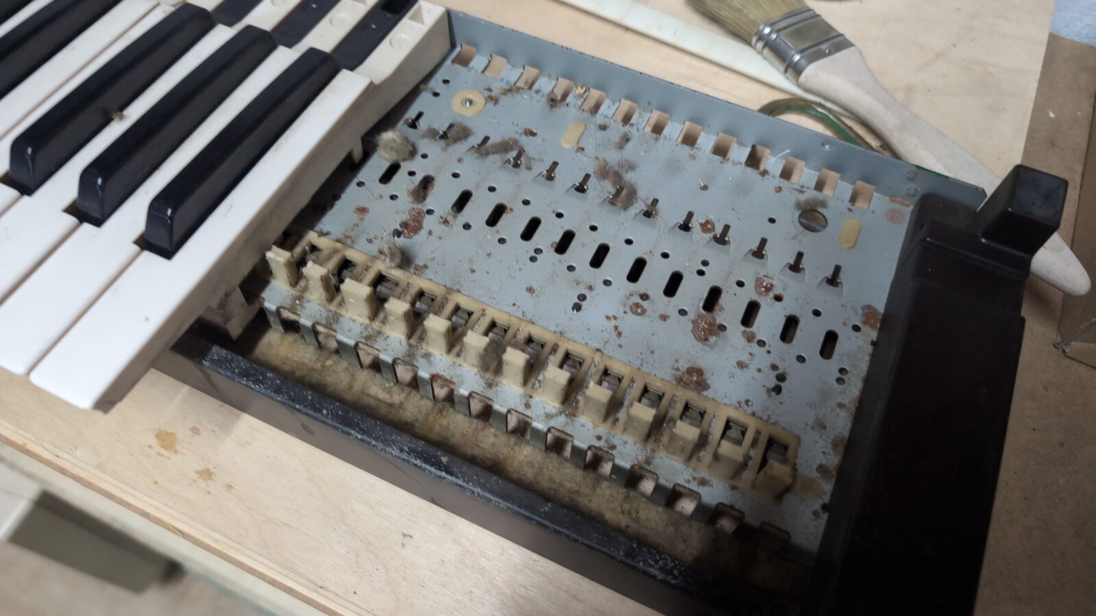
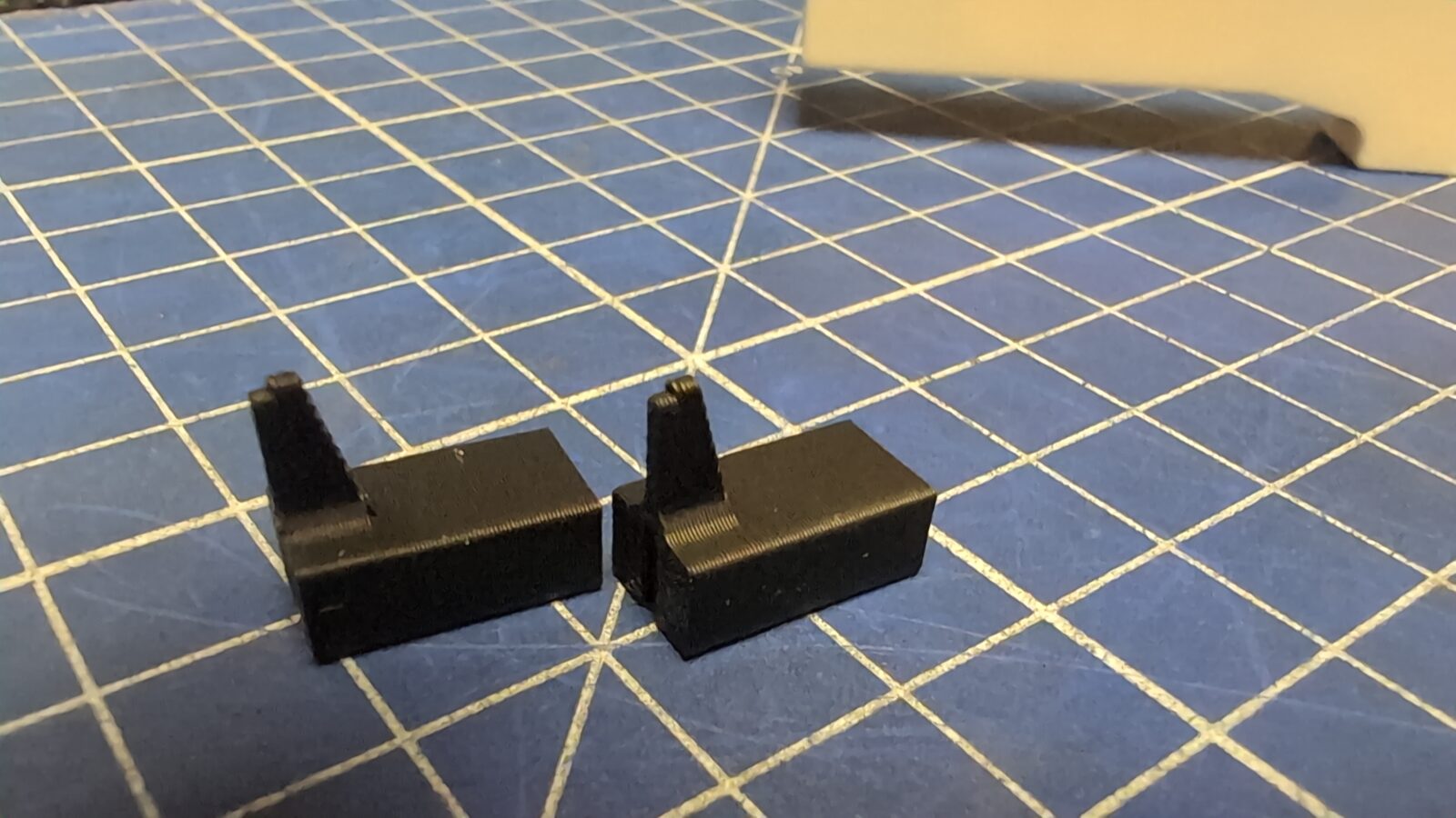
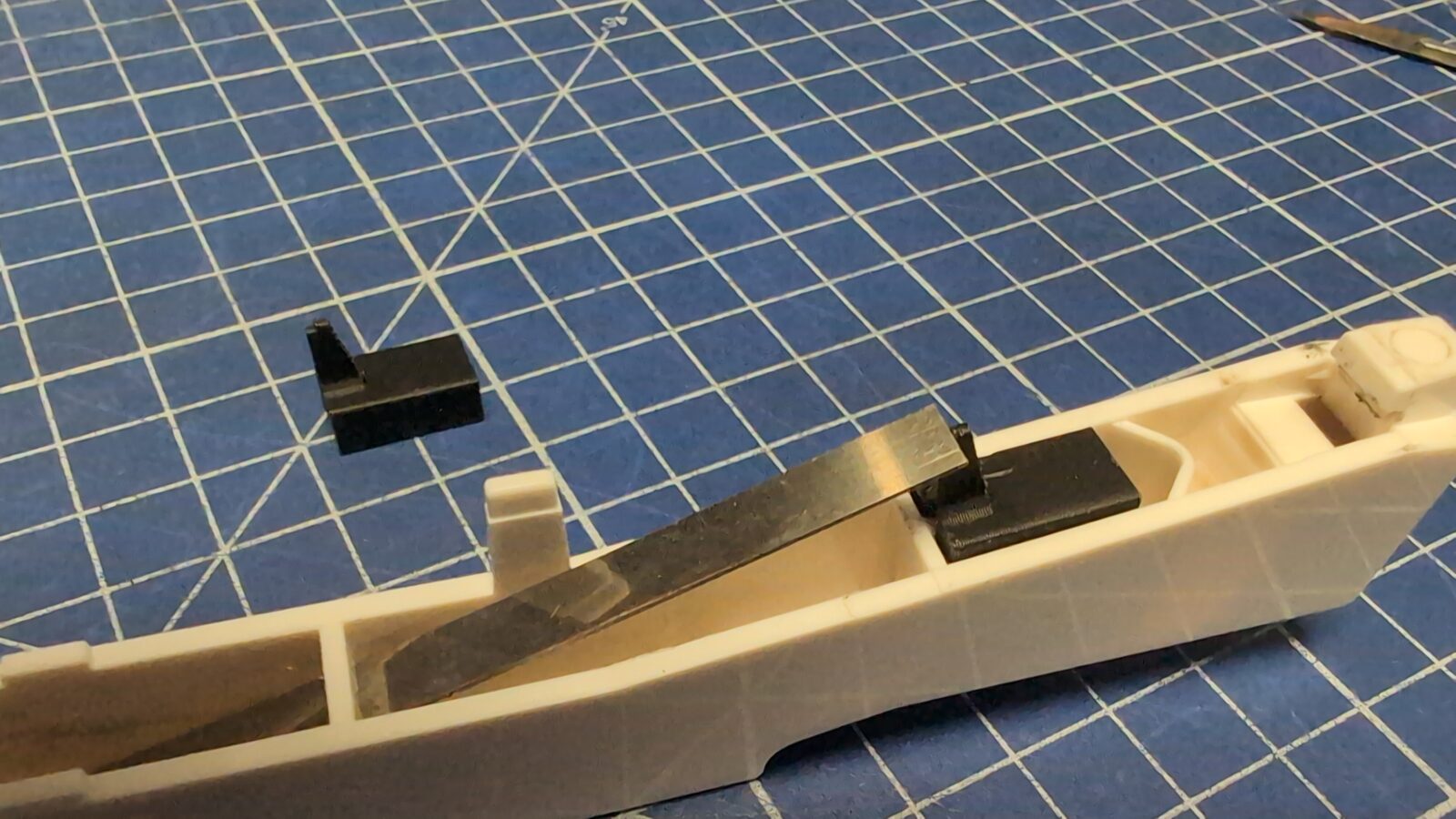
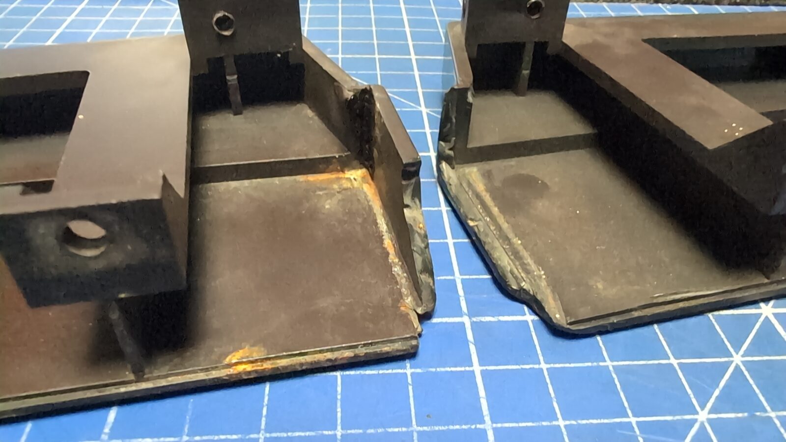
Here we go with the first fix. I’ve noticed that some of the keys are missing a stud that supports a springy sheet of metal.
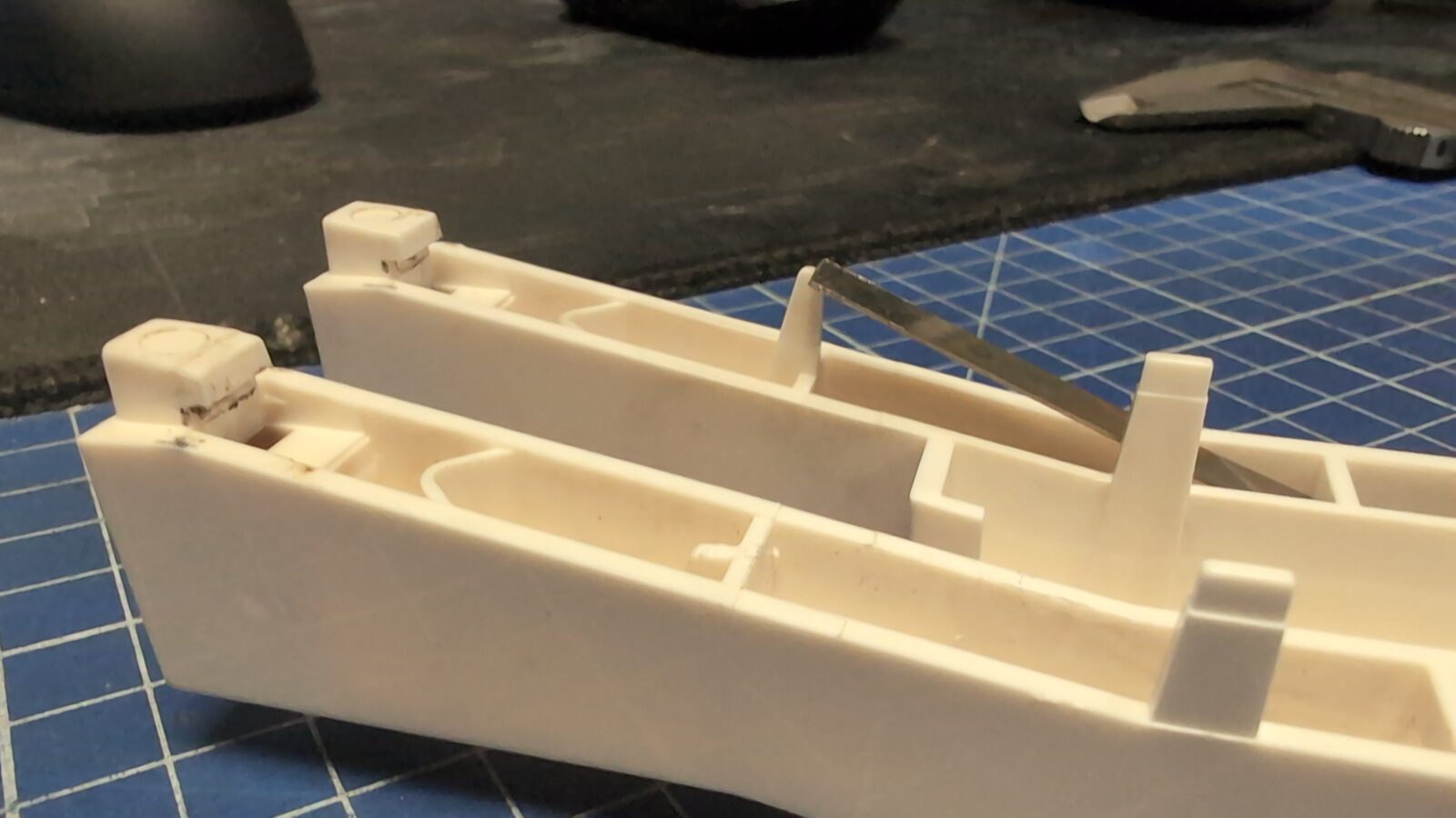
Without it, it is impossible to mount that springy-thingy, so I created a model and 3D printed a fix (all models available at the bottom of the blog post)
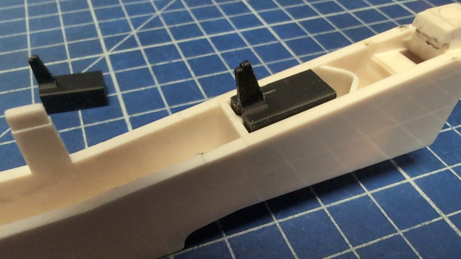
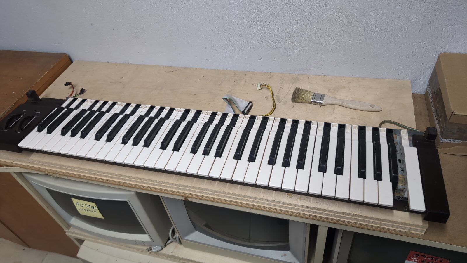
Keyboard cleaned and partially fixed (not really), but still missing a key, and more on that later.
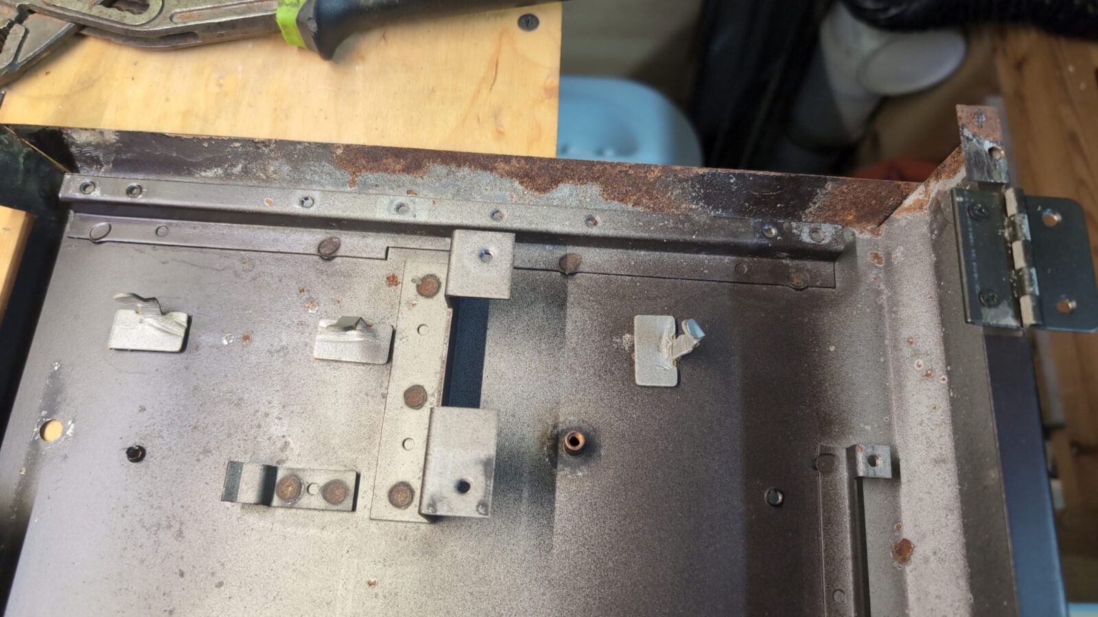
I moved on with case restoration.
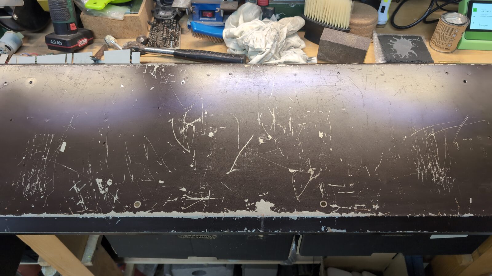
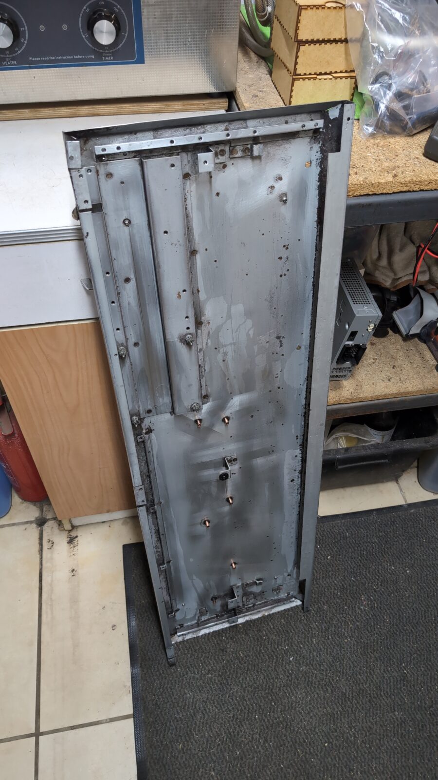
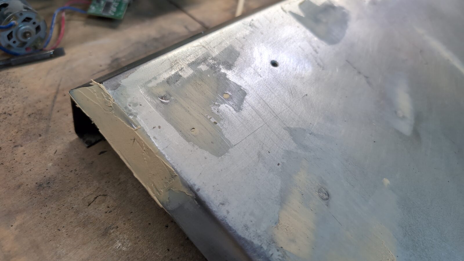
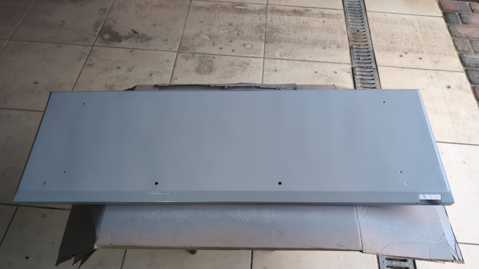
The case
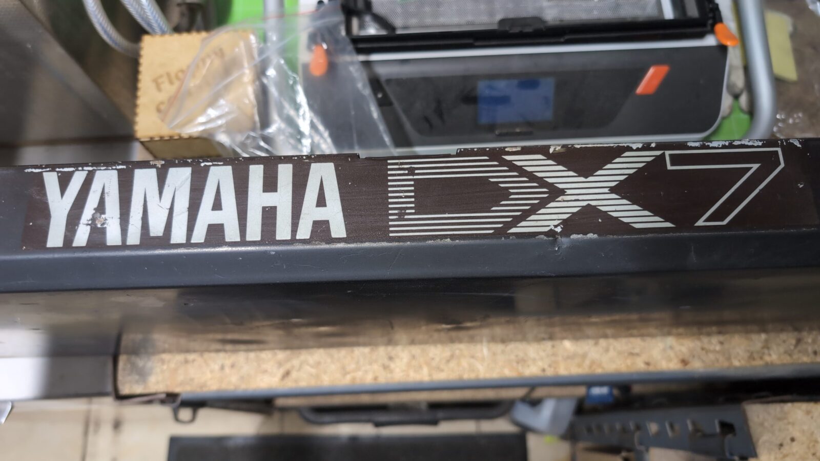
As you’ve probably noticed, the case of this poor Yamaha DX-7 was in really bad shape. Lots of dents, rust, and heavy scratches everywhere.
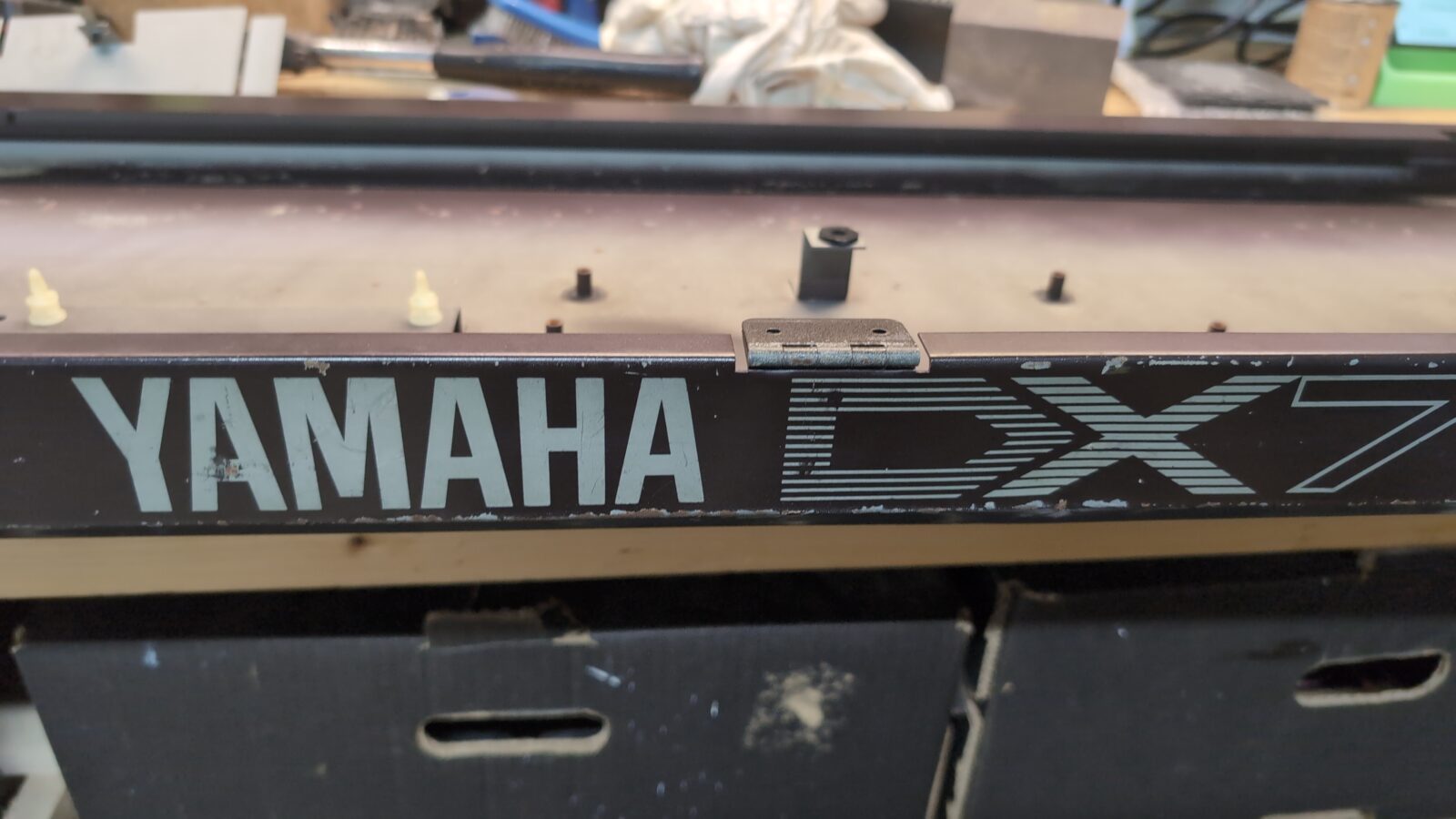
I decided to paint the whole case; however, I didn’t want to lose the famous YAMAHA logo, so this had to be covered with paper tape (first major mistake).
The usual stuff followed – initial sanding, applying putty, sanding again, and applying a first layer of undercoating.
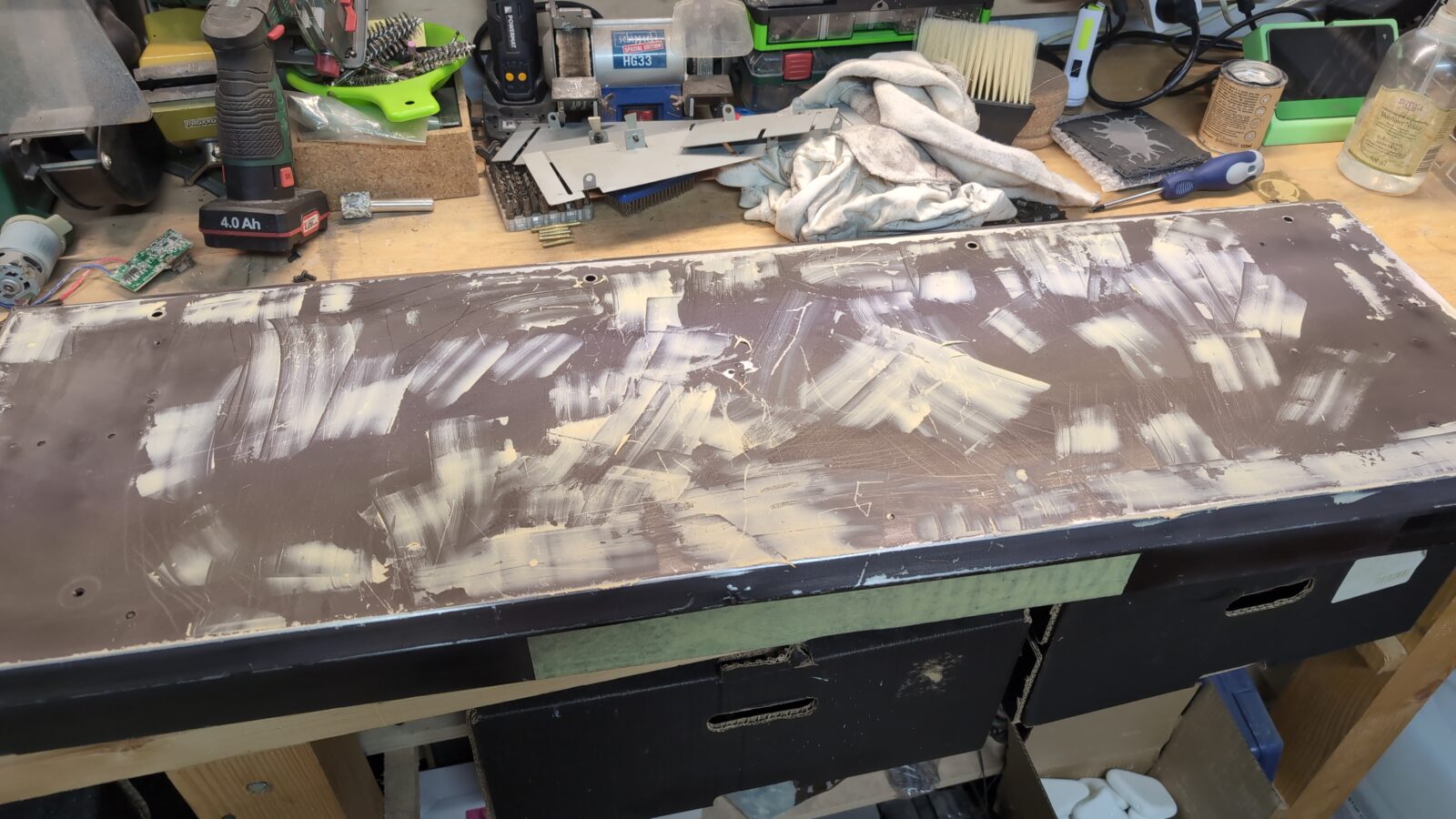
Once the undercoating dried, it became obvious that it was a crappy job, not worthy of a serious restoration. I already know for sure that fixing particular scratches never ends, and you end up fixing such a surface for days.
It took me a while to figure out the upcoming solution, and I was a bit scared that I wouldn’t be able to pull it off, but still YOLO side of me pushed me further 😀
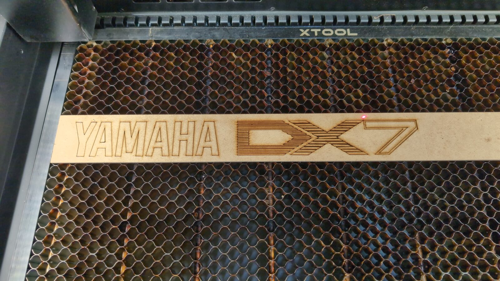
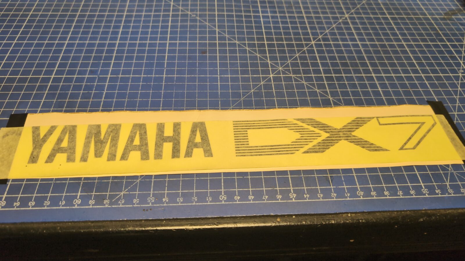
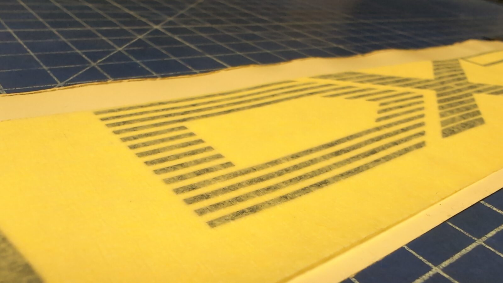
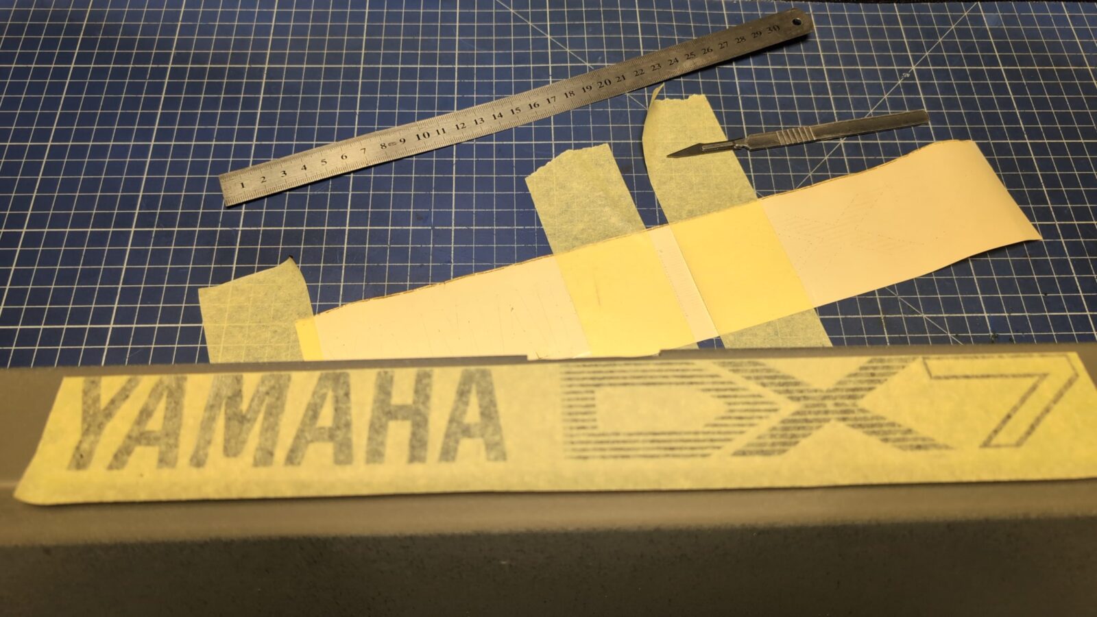
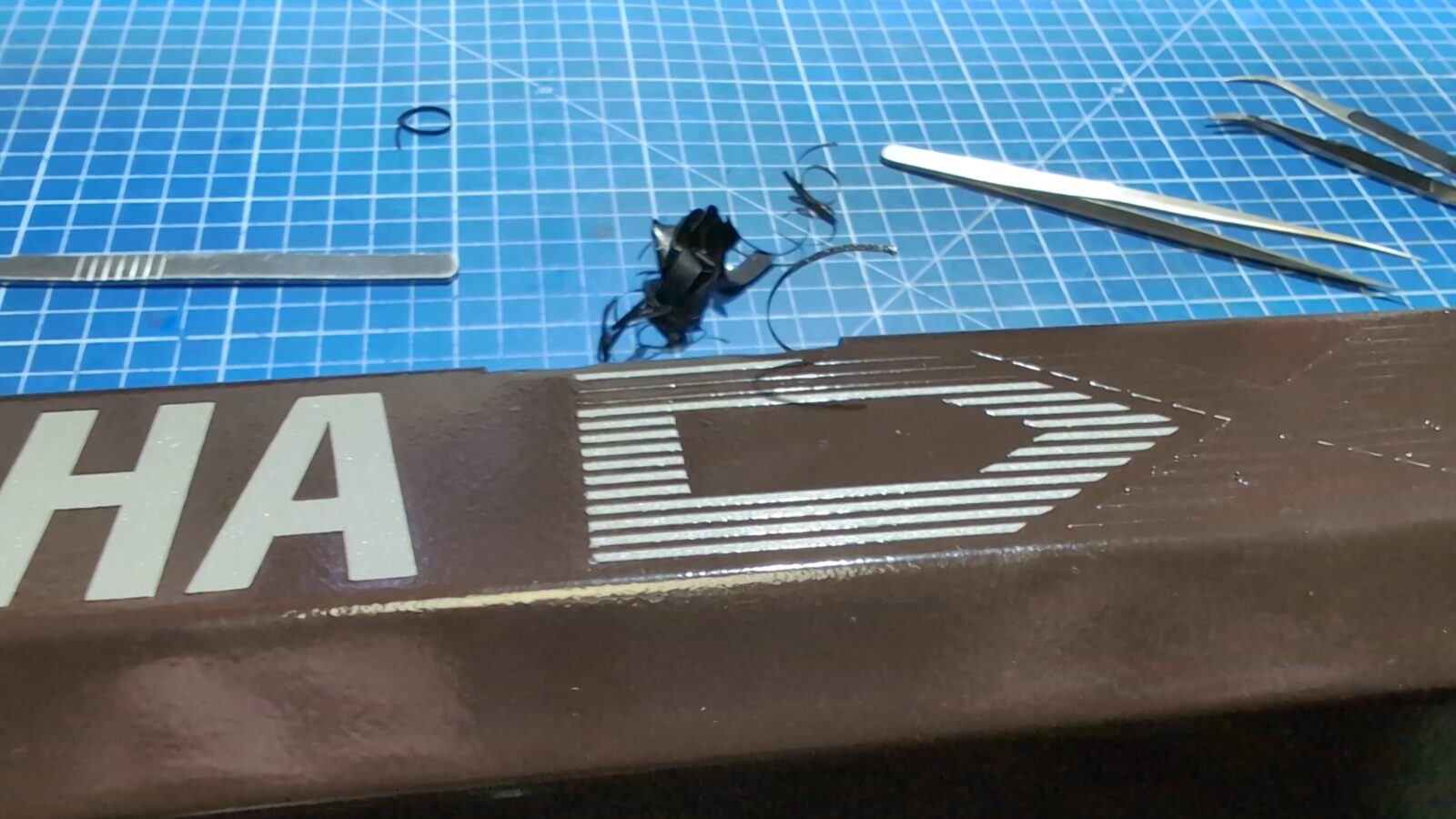
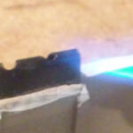
The plan was to prepare a “YAMAHA DX-7” logo in Inkscape, laser-cut a vinyl, strip the whole paint, fix all dents, and remove the rust and repaint the whole thing properly.
I started working with a model in Inkscape, but fortunately, I was talking to Willy/Lamers on an IM, and he’d thrown a hint to simply search for it on the internetz! DUH … I am such a dumbass that I didn’t figure it out lol. Thank you, Willy! 😀
A few moments later, I laser-cut the logo from thin MDF and could measure it against the original one still on the case.
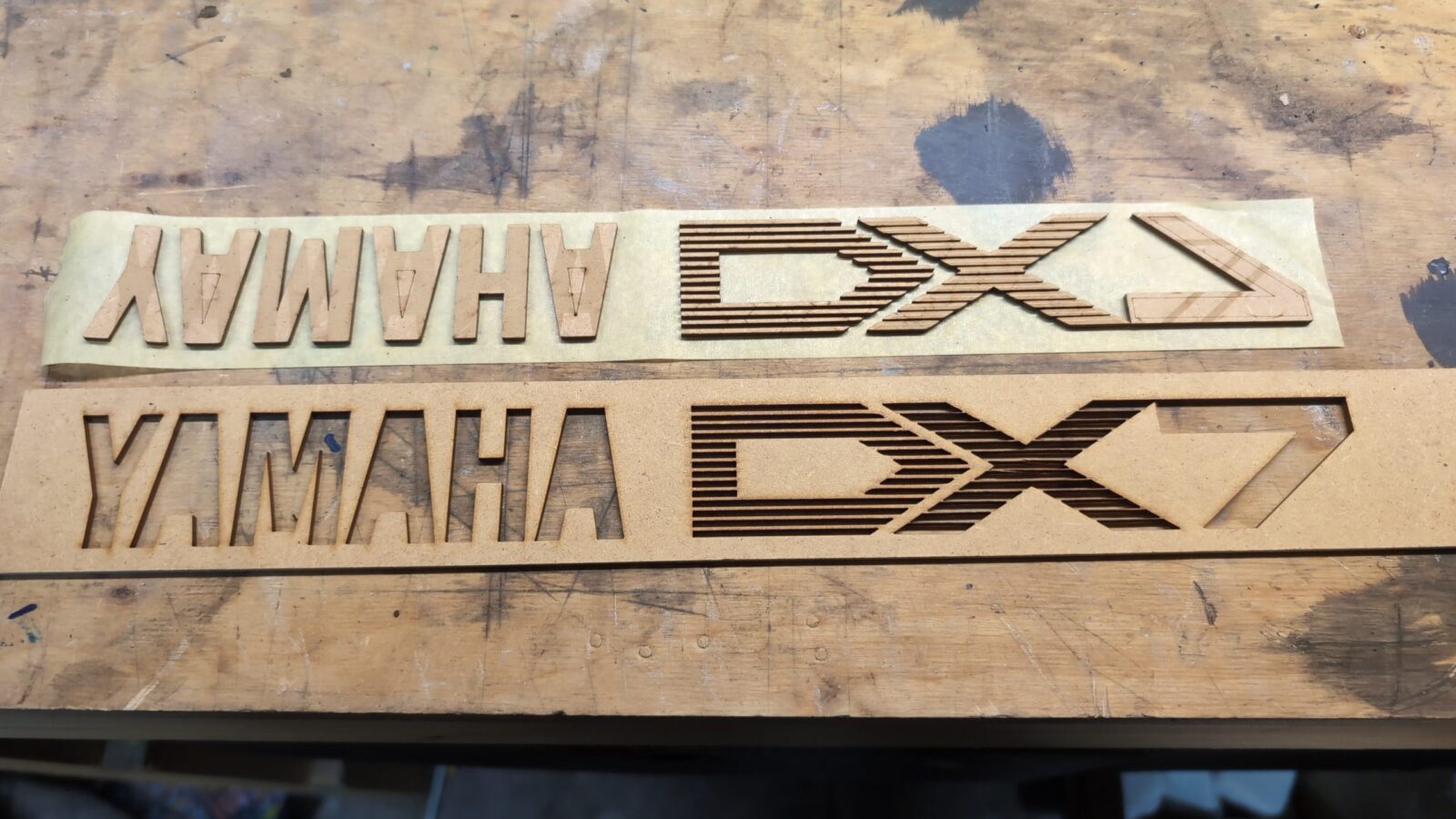
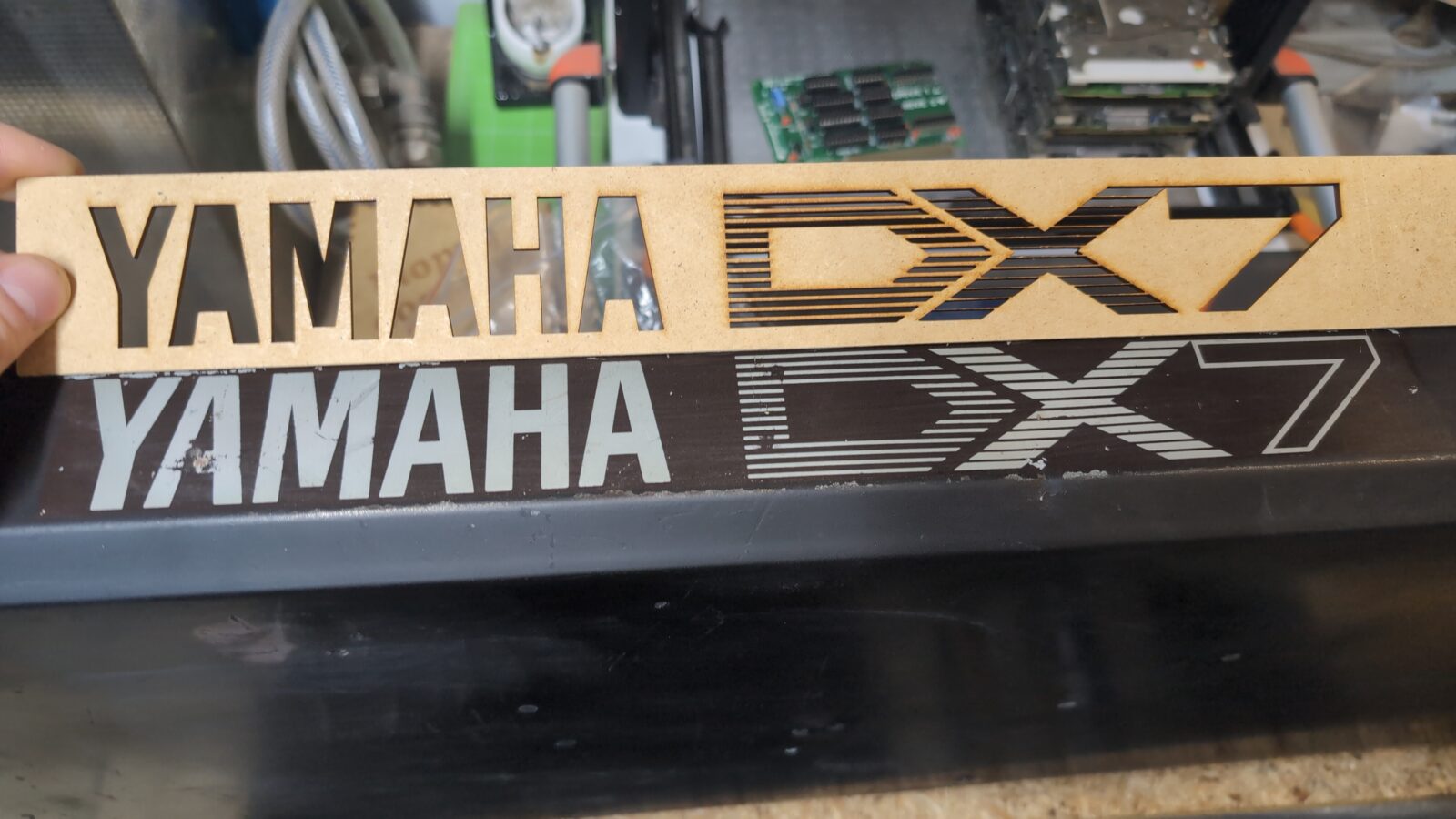
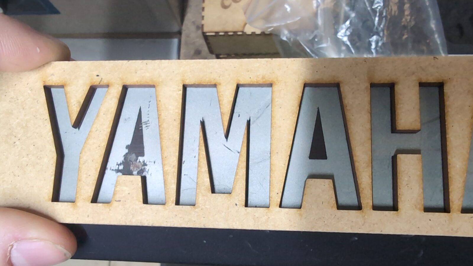
Idea approved, so I moved on to a vinyl sticker.
Aaaaan, ready for transport tape once the case is painted. YaY! 😀
The case makeover continued
With the logo issue resolved, I could order some chemistry and start working on the metal case.
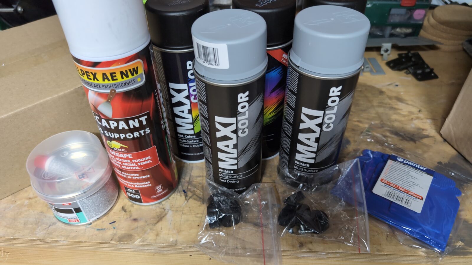
First of all, I had to remove the old paint with a paint stripper(already covered on my blog while working on an ancient typewriter), wash it, and wait till it’s dry.
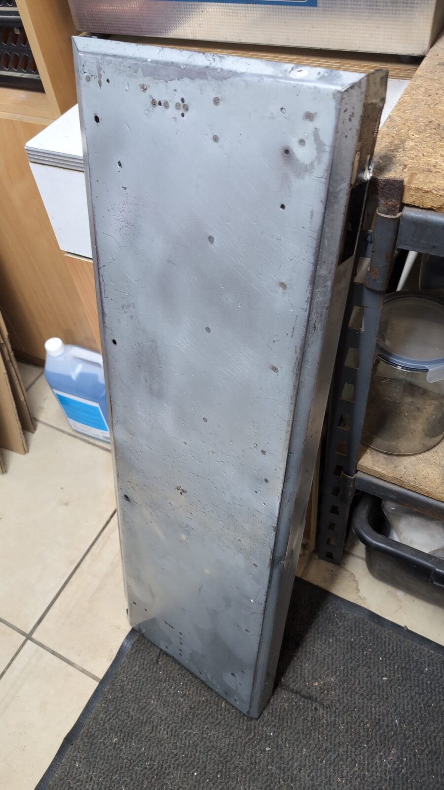
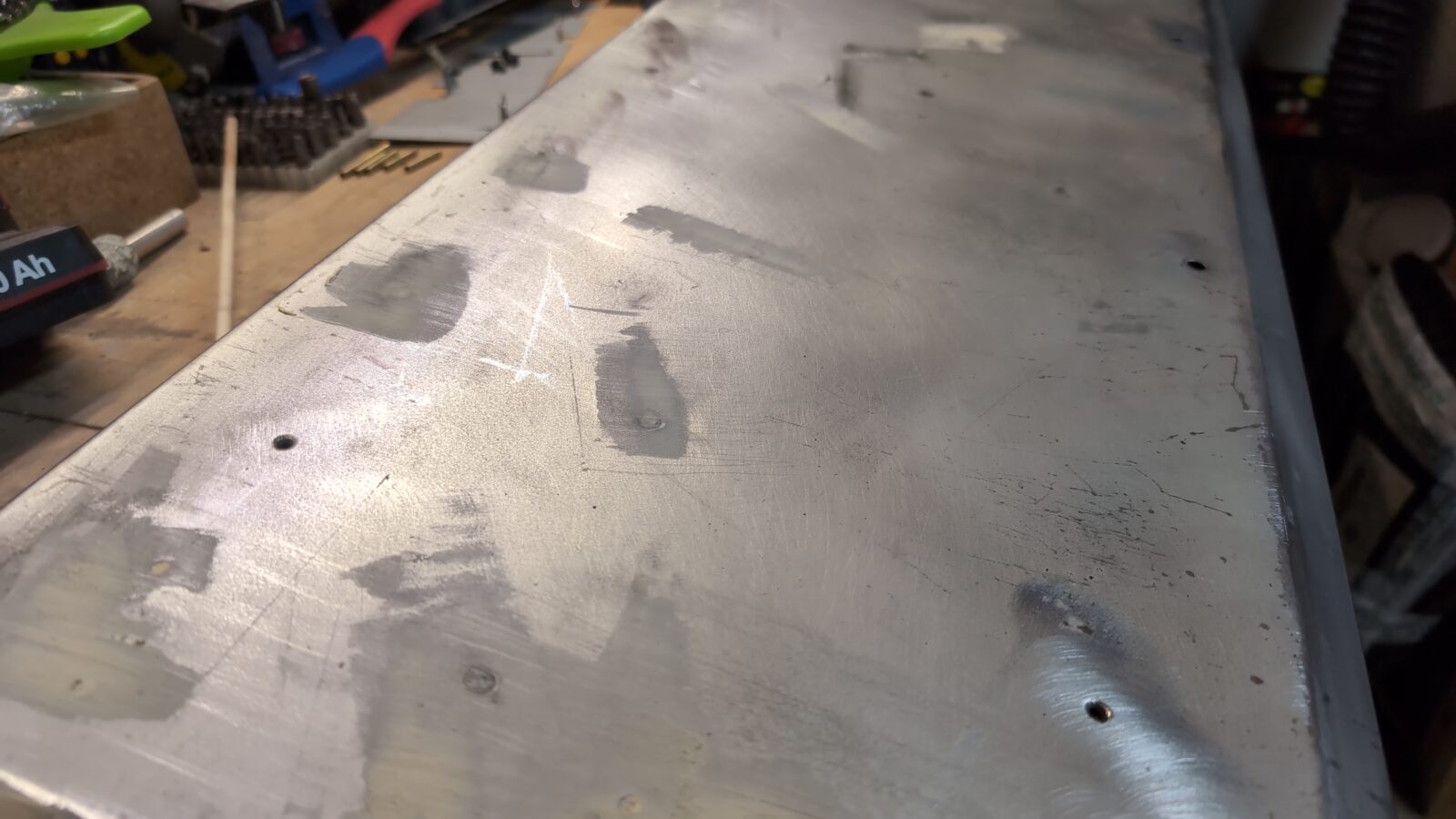
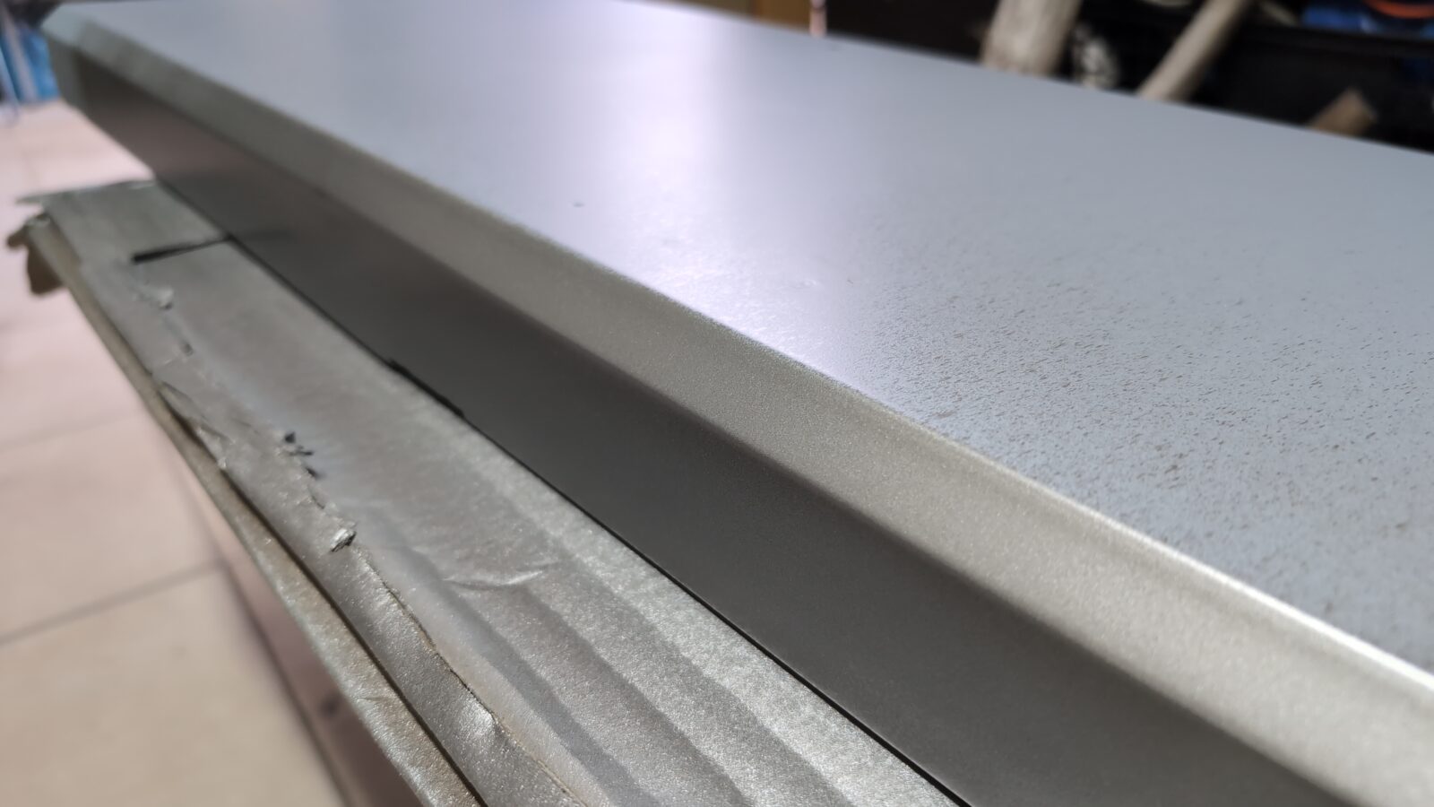
Metal works started, meaning I removed all the rusty spots, dents, and sanded it off for better paint adhesion.
…followed by puttyfication 😀
I also had a minor problem with an original sticker, but that was solved a bit later.
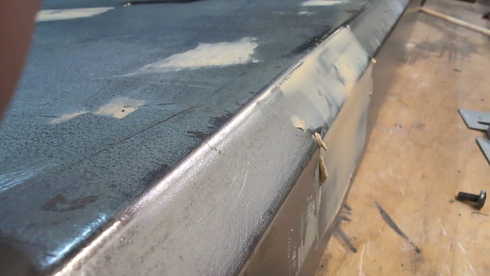
Next, the layer of undercoating was applied, followed by another layer of silver logo paint.
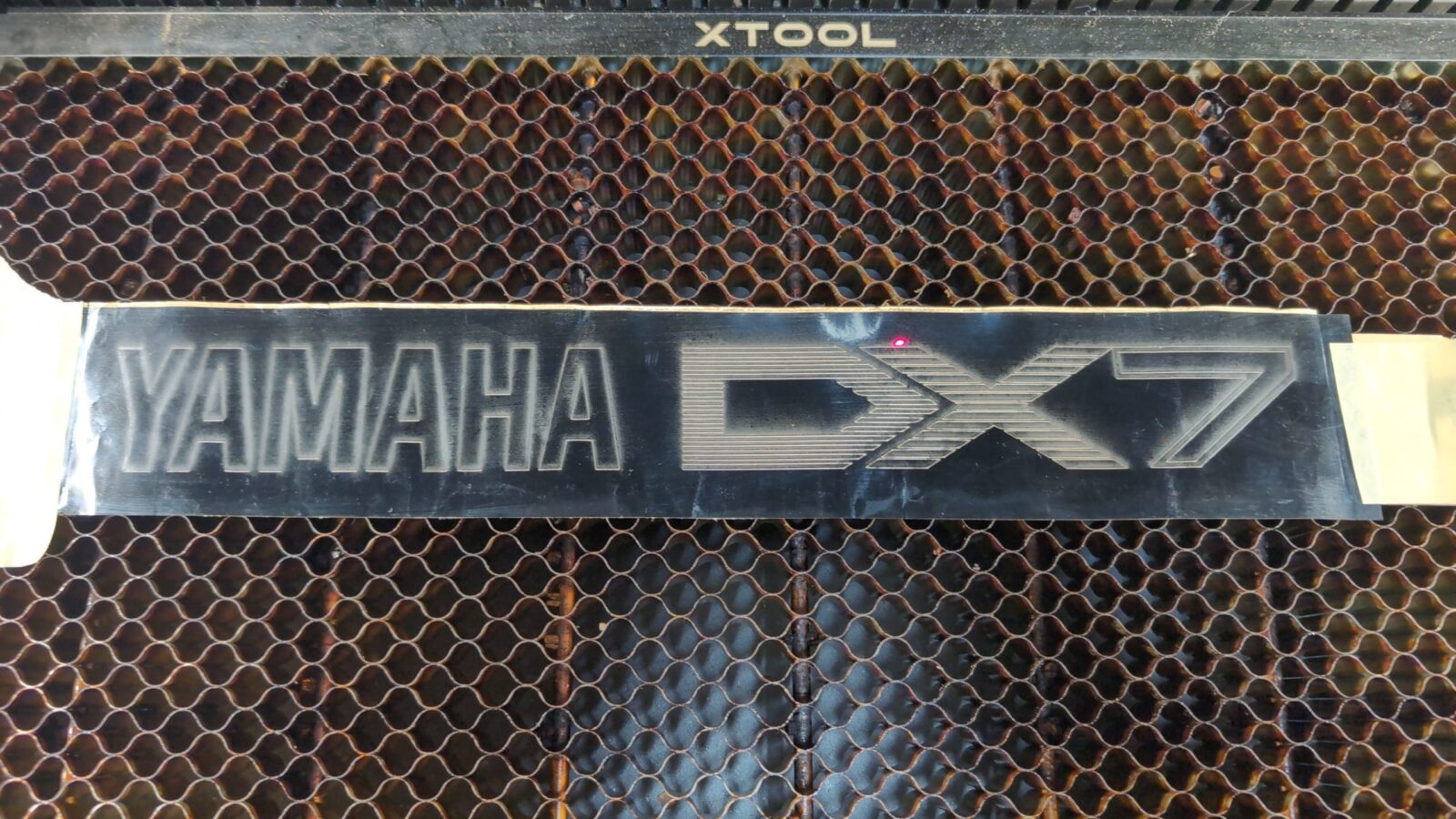
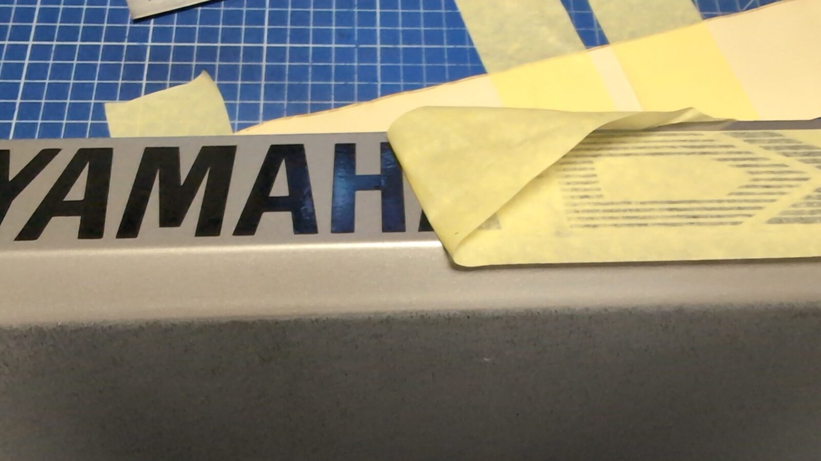
Now, I was ready to apply the previously laser-cut vinyl logo with the help of a transfer tape.
Now I could gently remove the transfer tape. Quite a fragile moment 😀
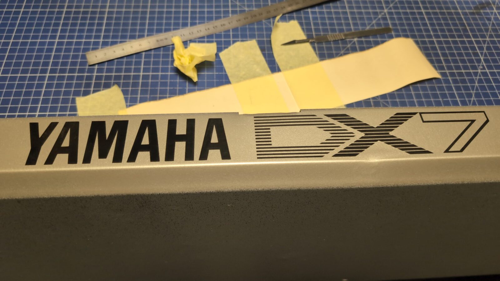
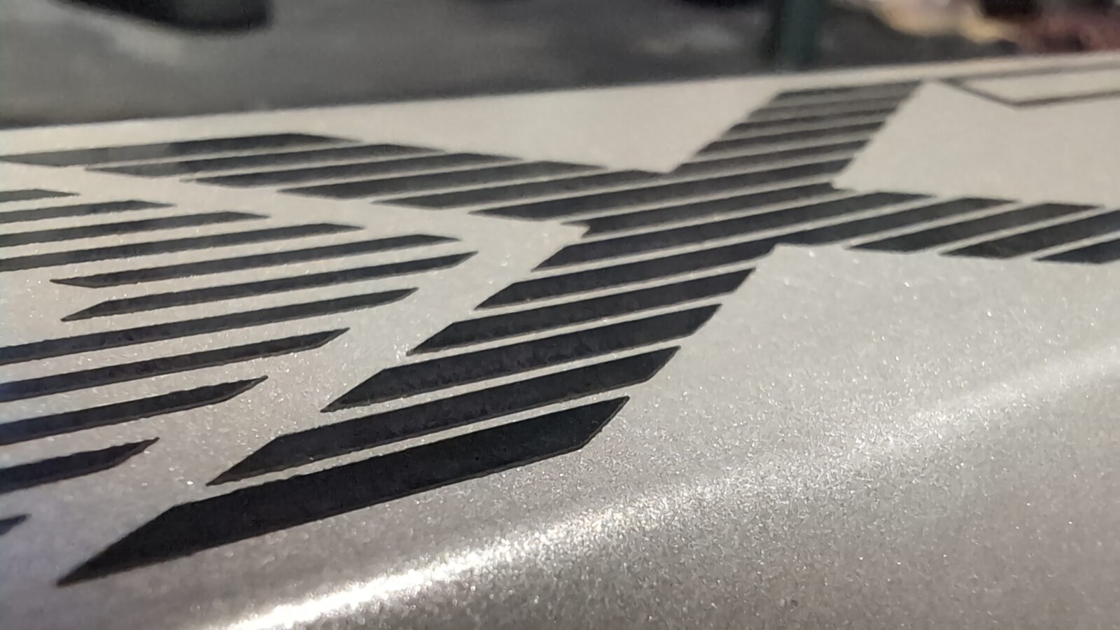
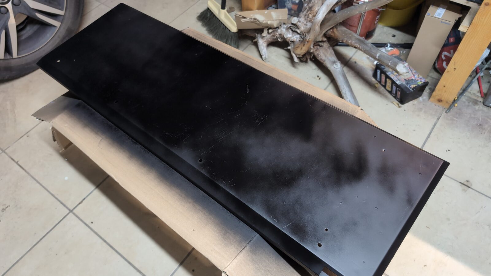
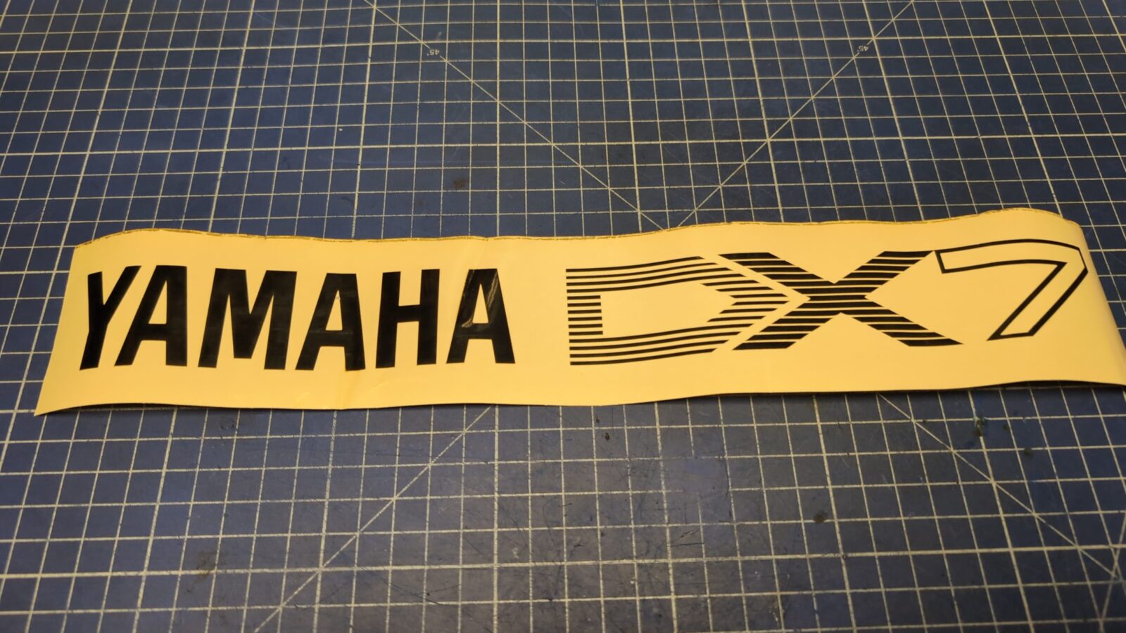
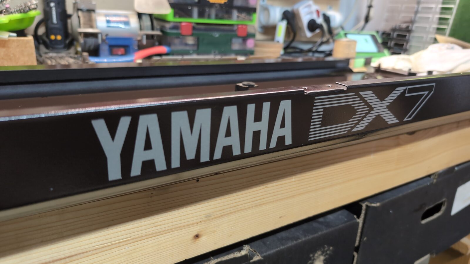
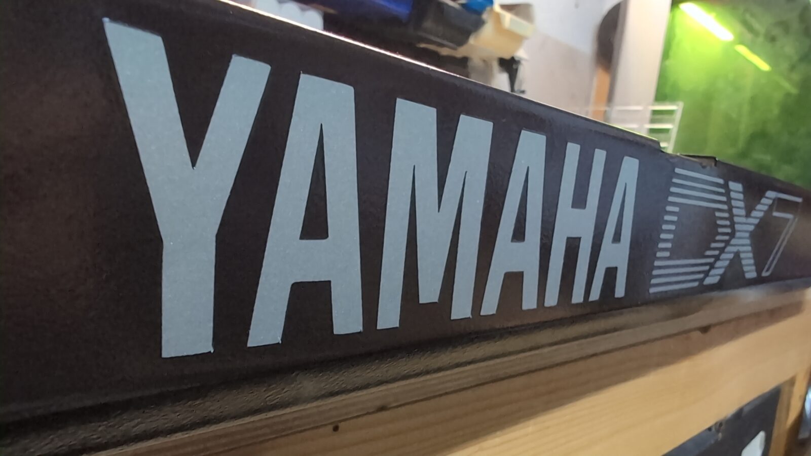
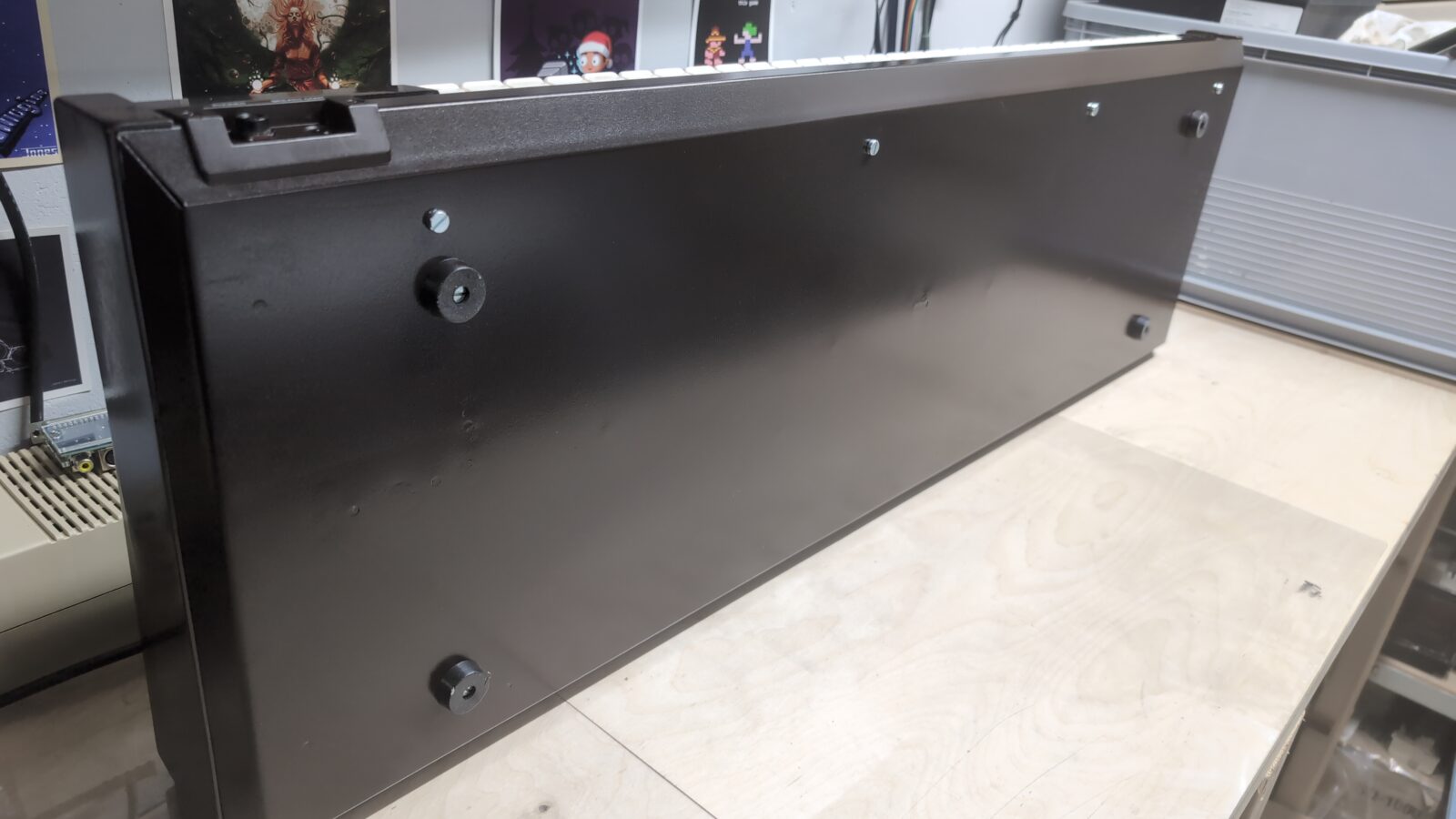
With all the above done, I could paint the whole case with the destination color that I had ordered specifically for this project.
As mentioned in one of my blog posts, this is done using computer spectrography, so it requires going to a professional paint shop to get it done. With the paint applied, I could start slowly working on removing parts of the vinyl sticker.
Seriously tedious job but satisfying at the same time 😀
Et viola!
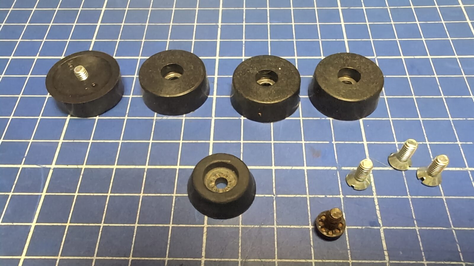
Meanwhile, freshly ordered rubber legs came in as the Yamaha had only one of them.
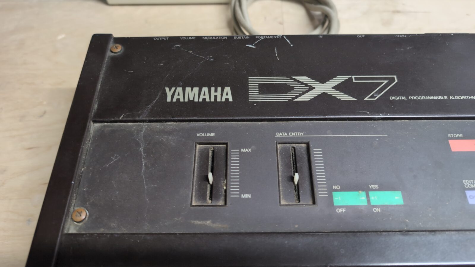
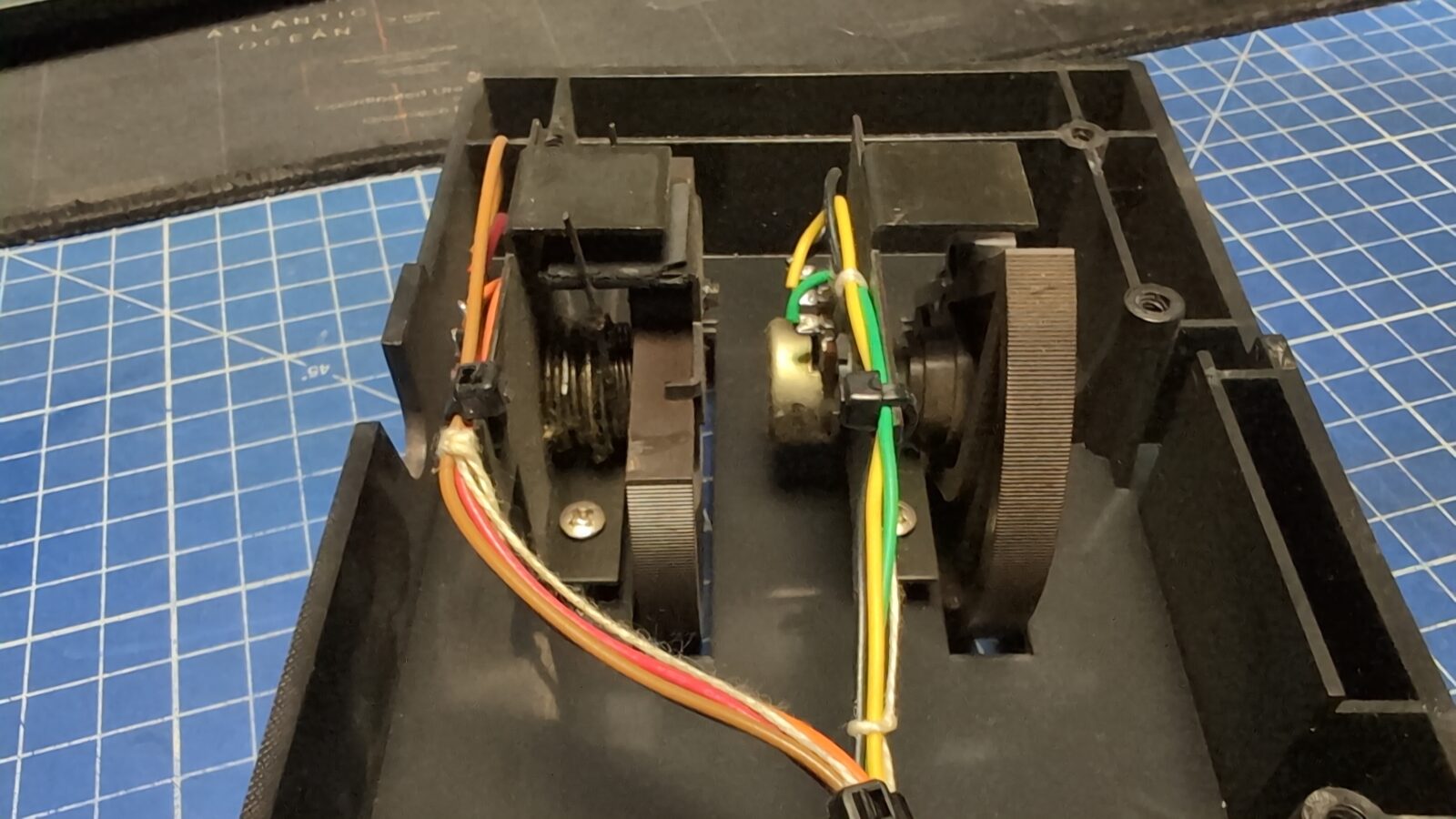
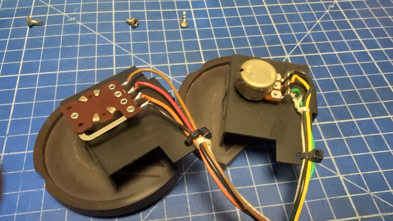
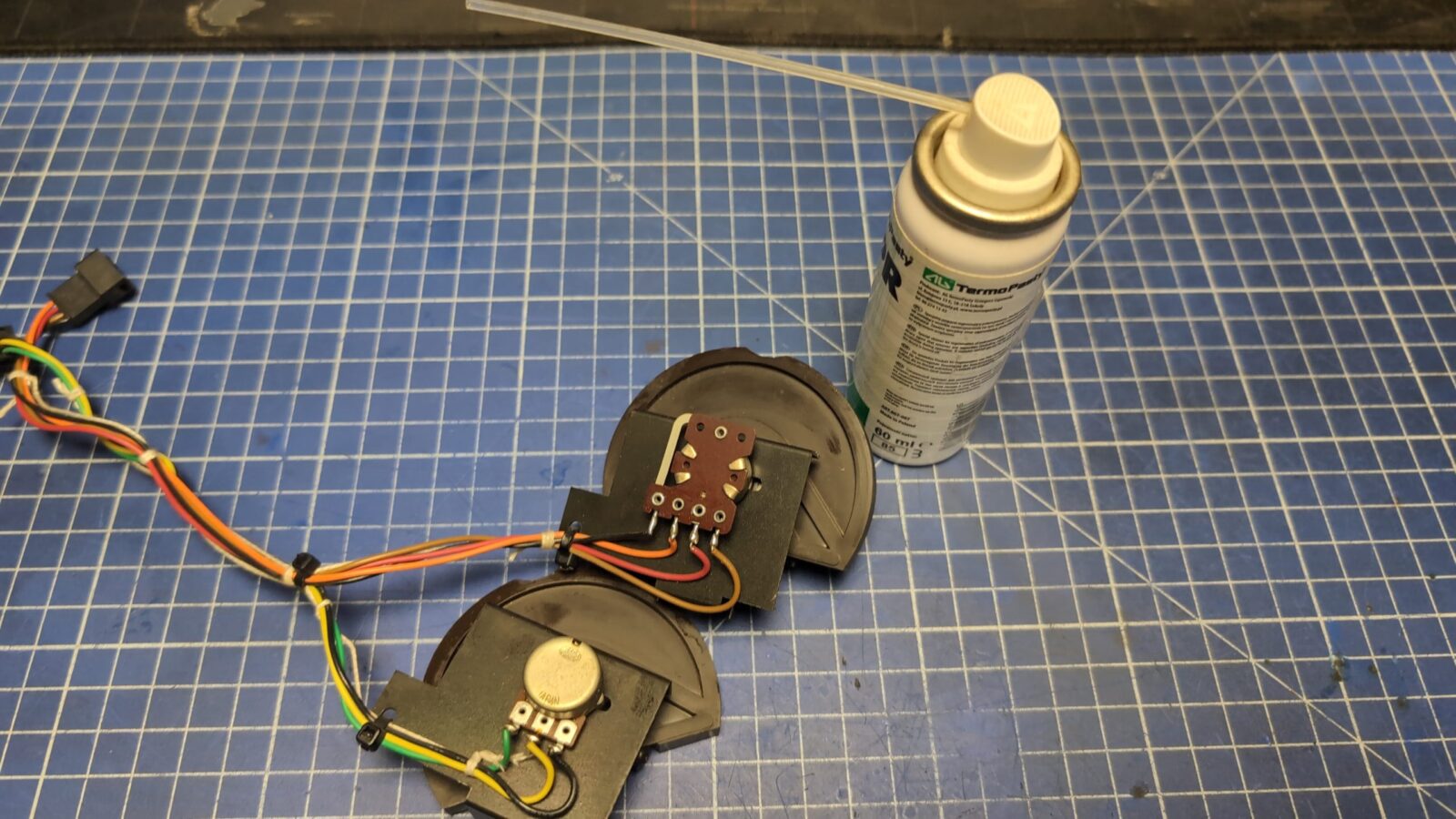
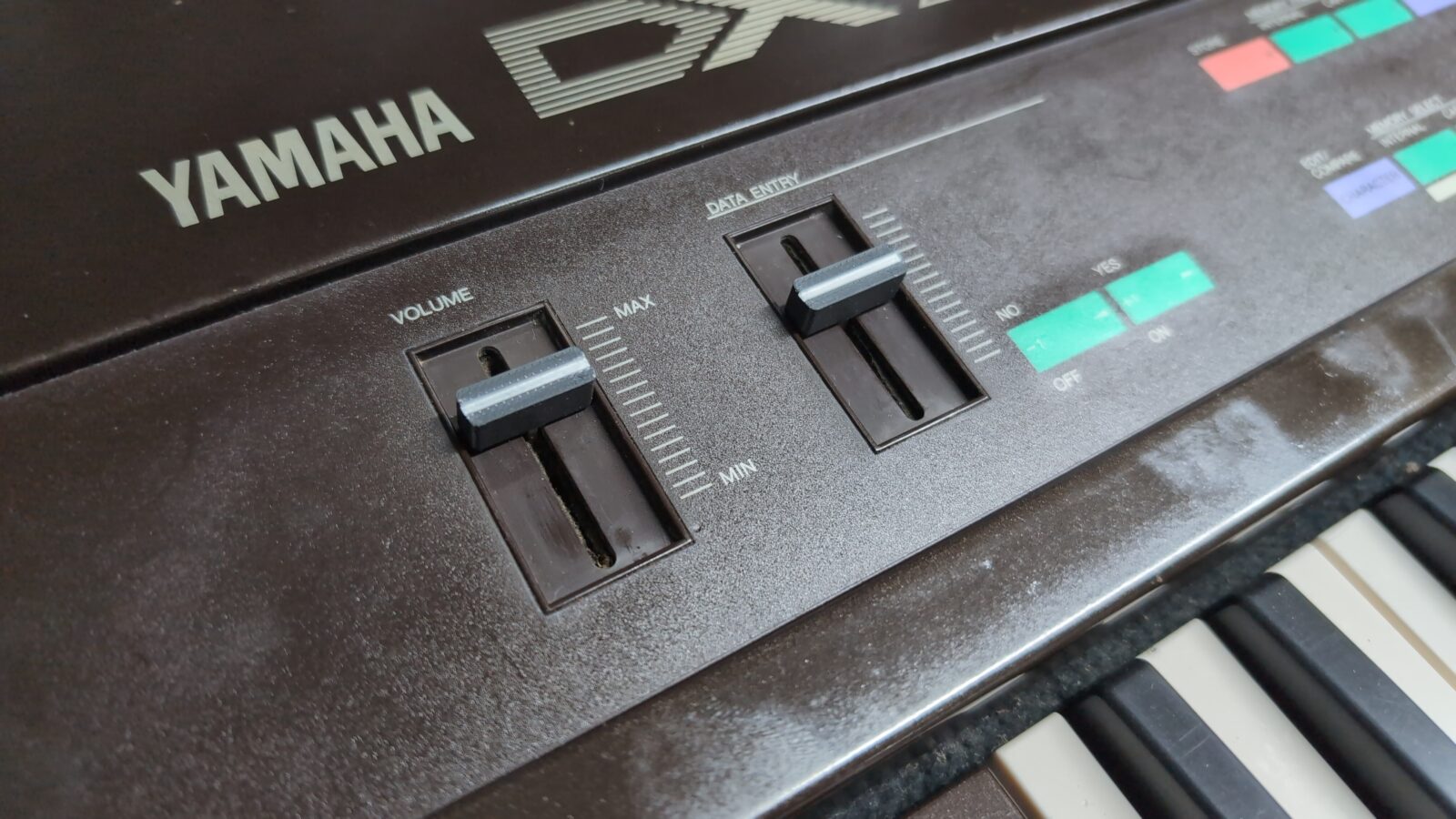
Main knobs
Not much here to do, but I had to clean up POTs and tighten some screws as both knobs were a bit too loose.
To clean up and lubricate POTs, I’ve used a dedicated chemistry.
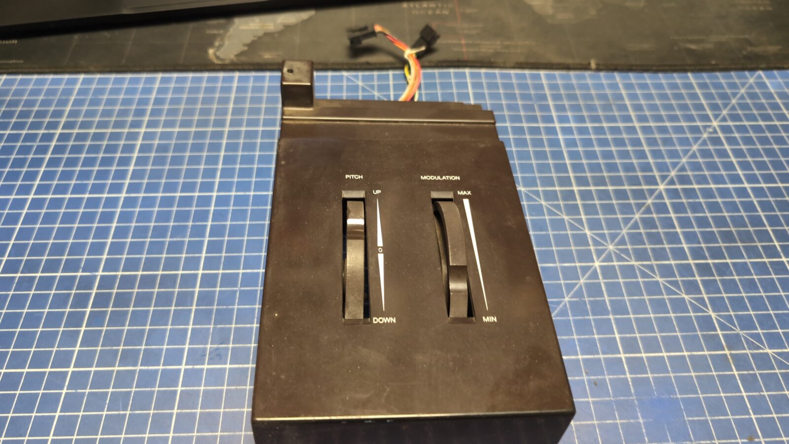
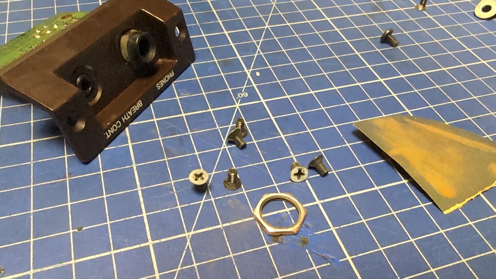
I’ve also sorted out the front panel JACK input.
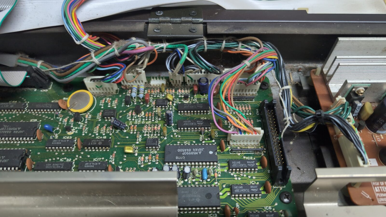
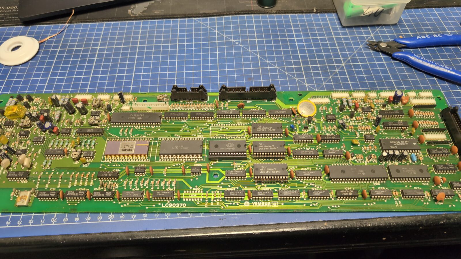
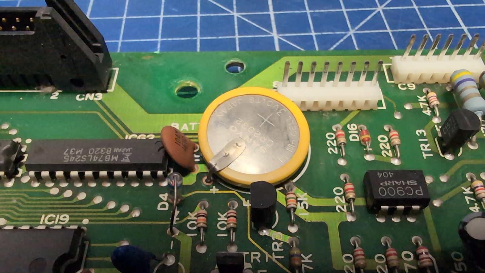
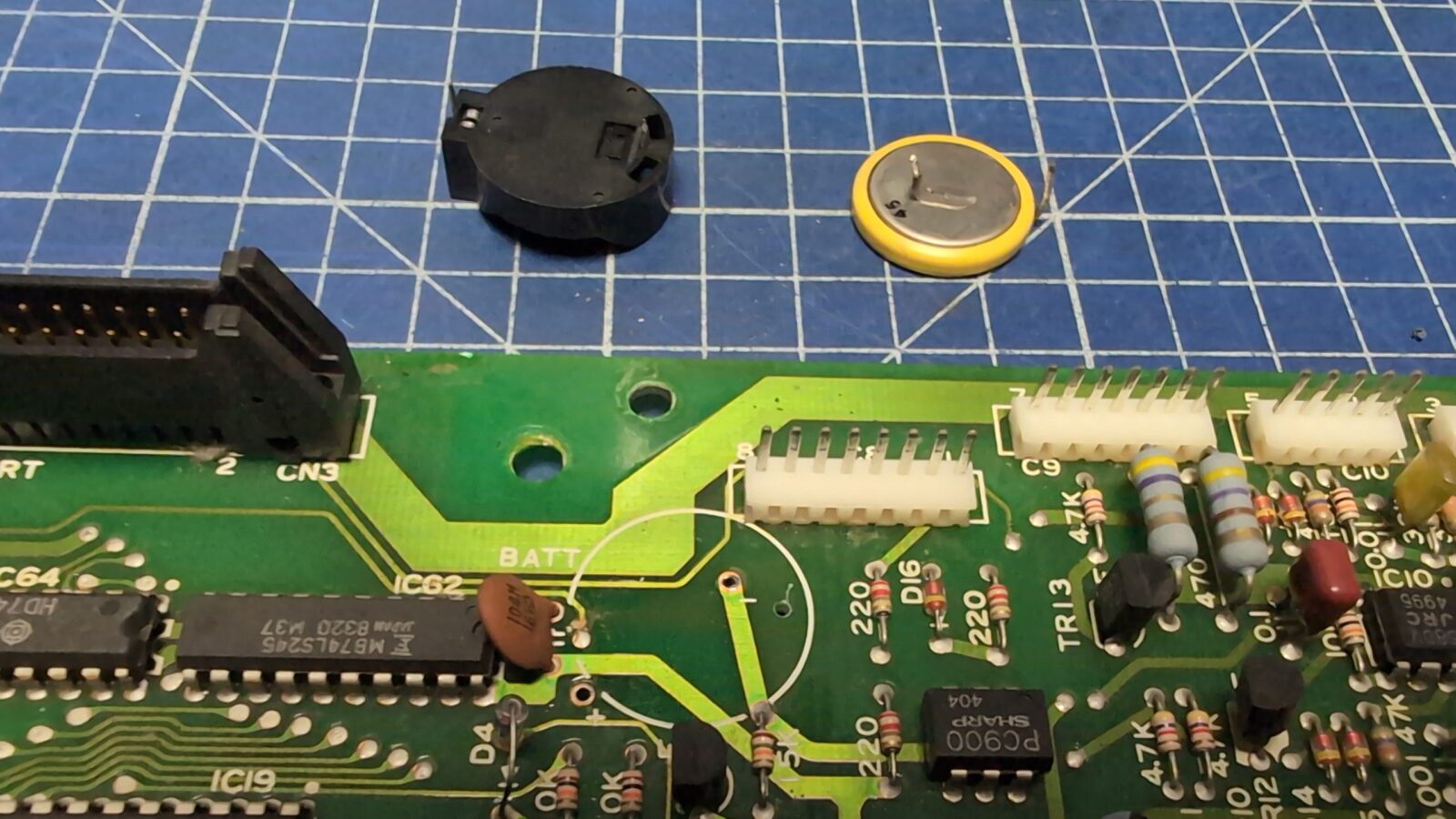
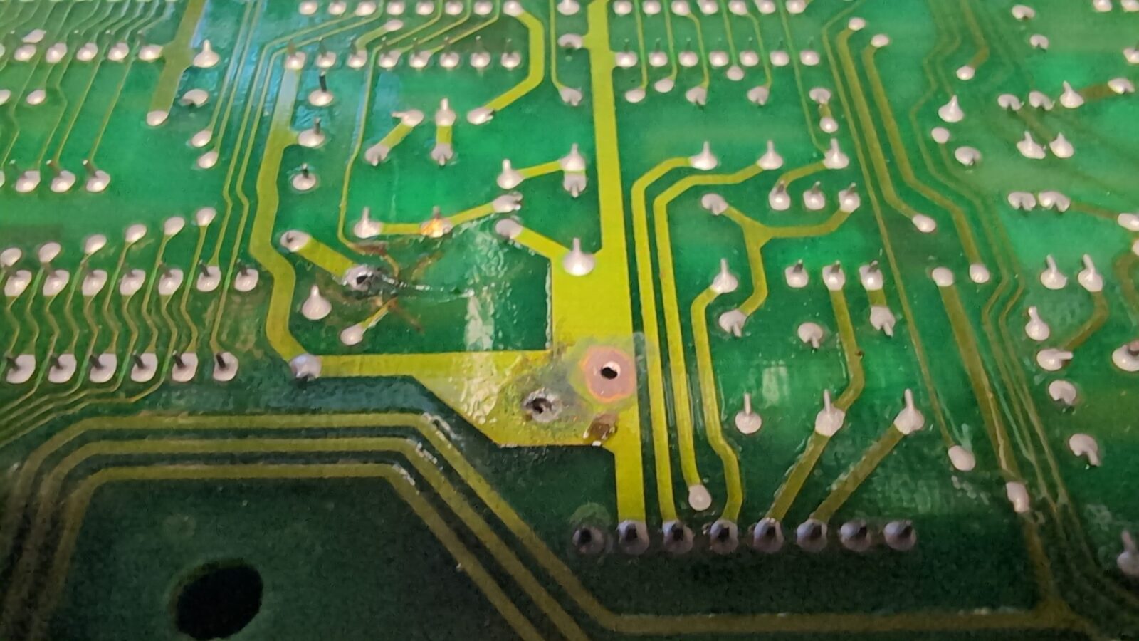
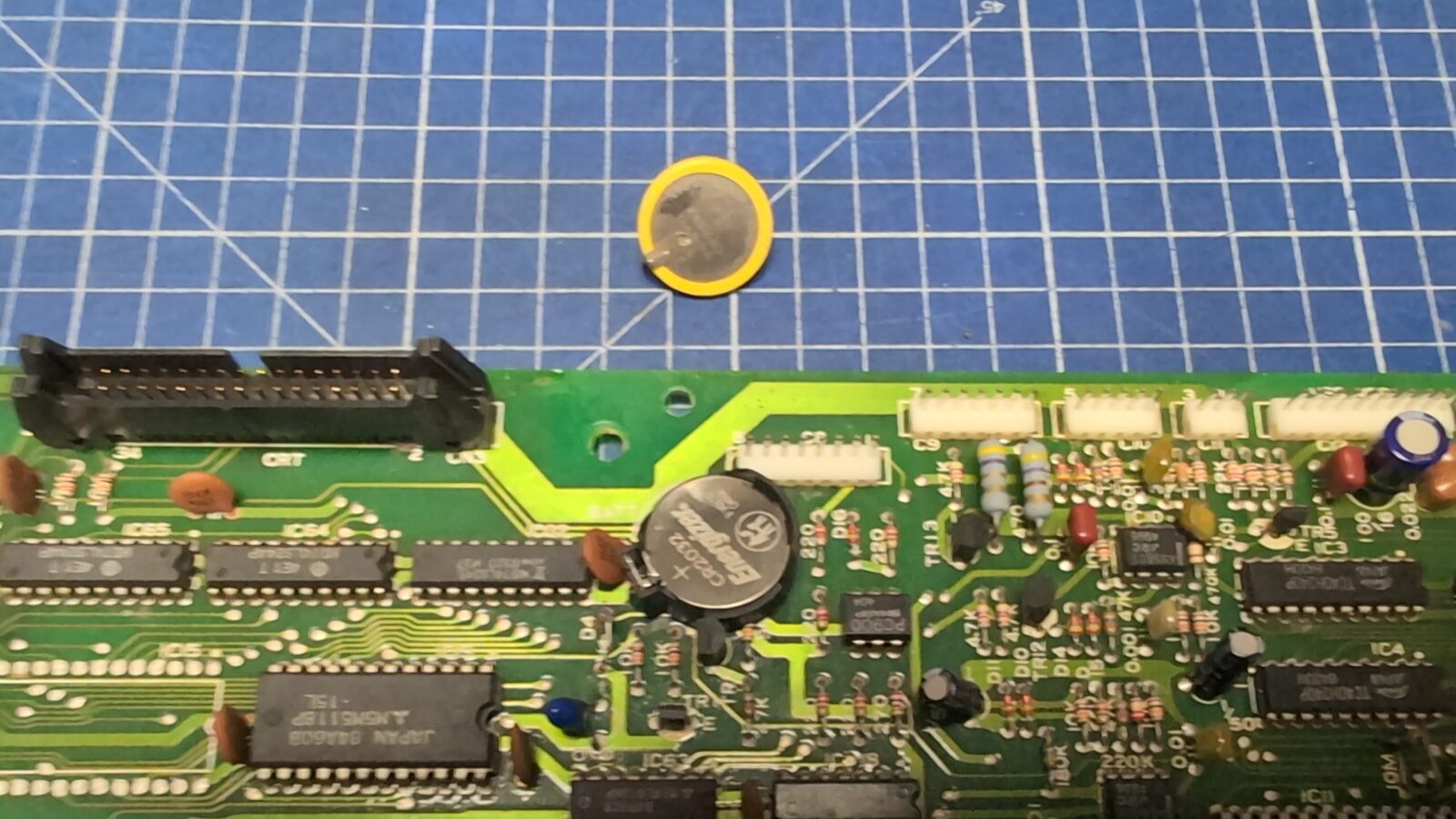
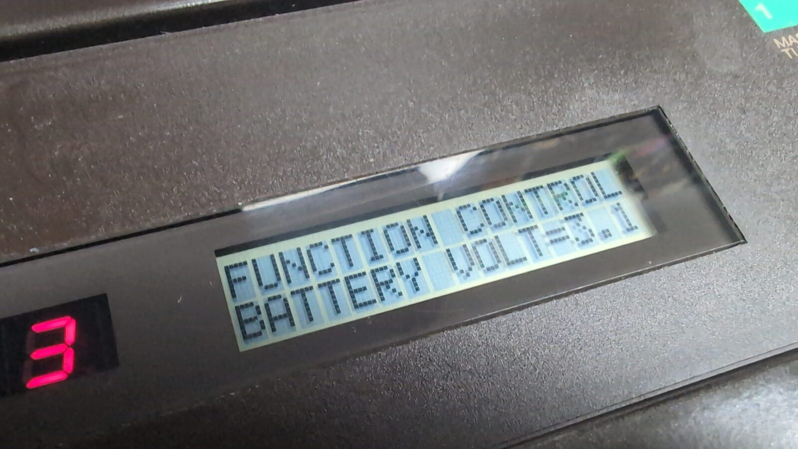
Main board RTC battery hax
The original battery on the mainboard was already dead, so I had to replace it. However, this is a battery that is soldered directly to the PCB. I’ve figured that I can install a basket for it. The only issue was that it didn’t fit, so I’ve drilled an additional hole in a GND plane.
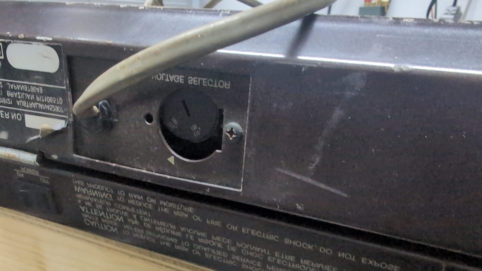
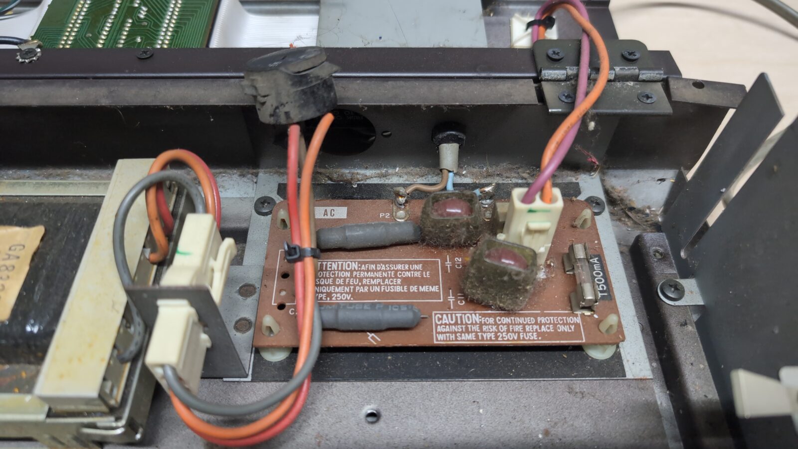
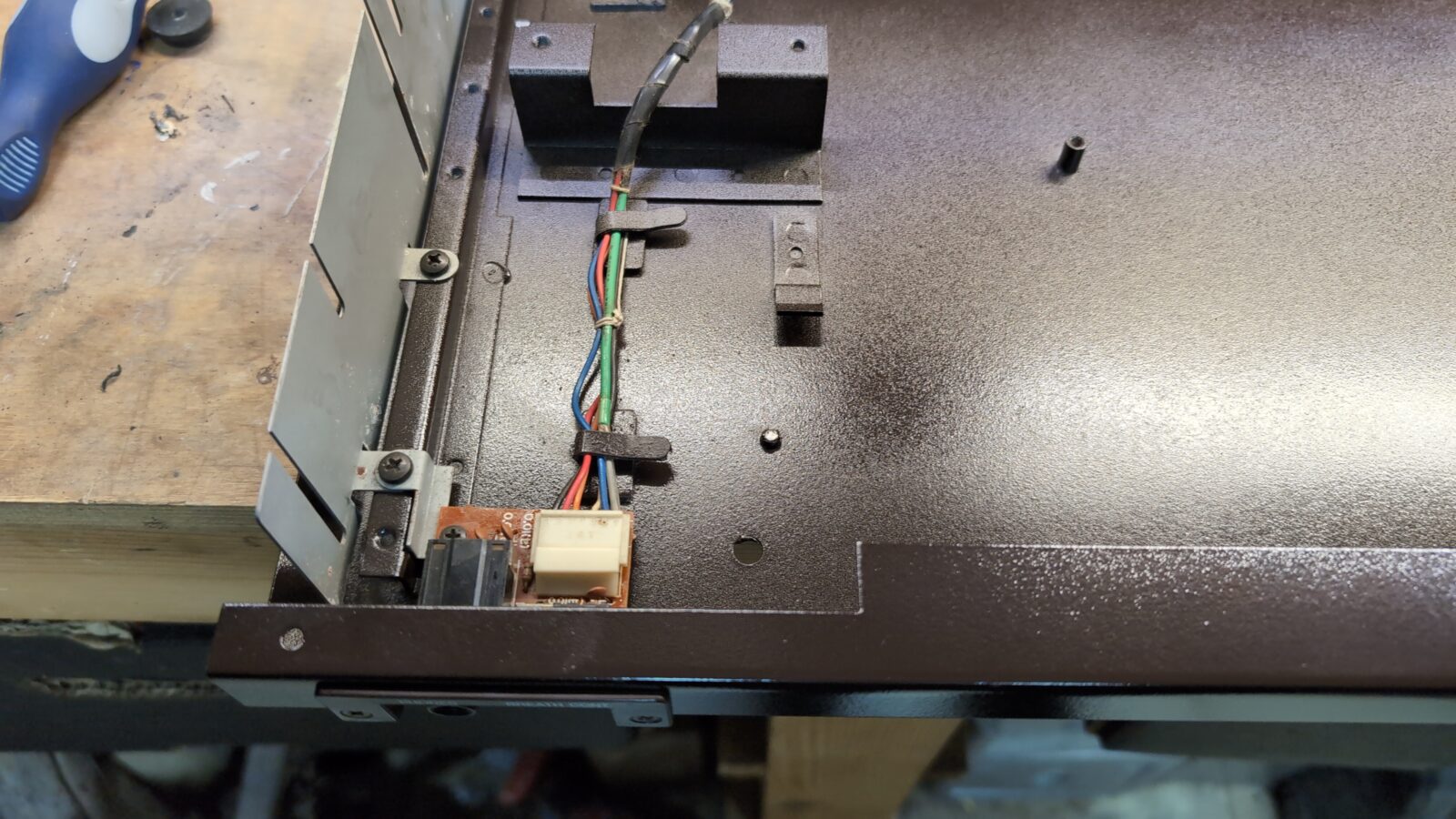
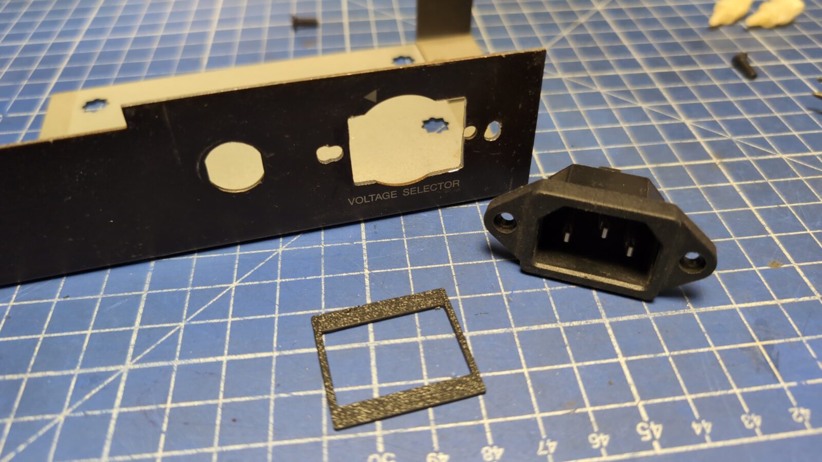
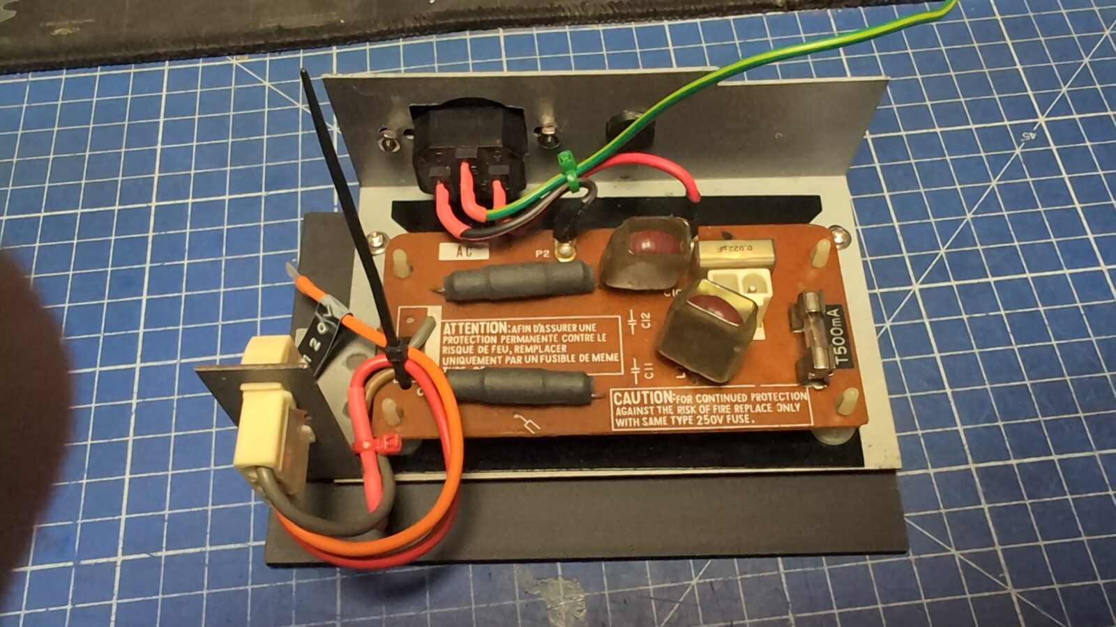
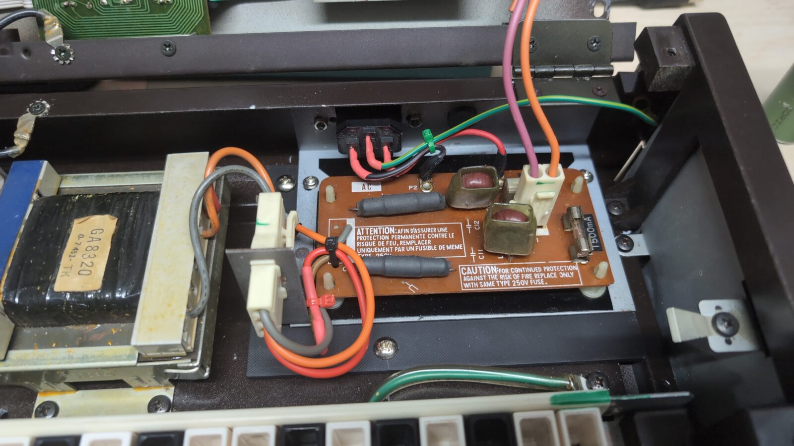
Voltage selector
As mentioned at the beginning of the blog post, Arabek asked me to fix the original problem with a voltage selector. He also wanted me to install a standard PC power socket in place of the original selector, as it is a more convenient solution.
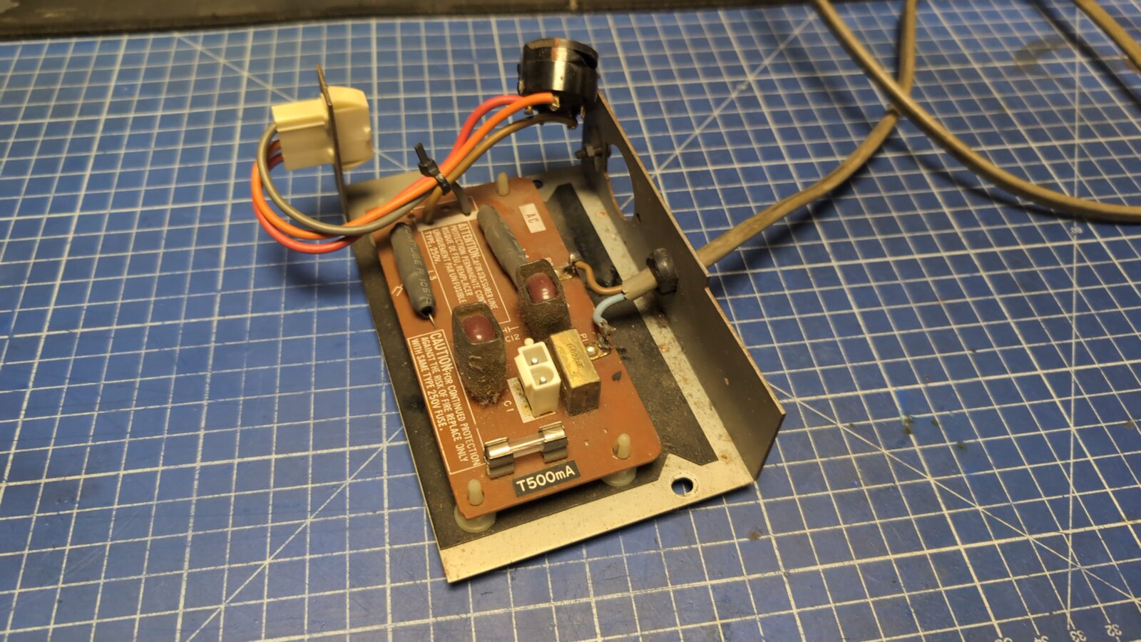
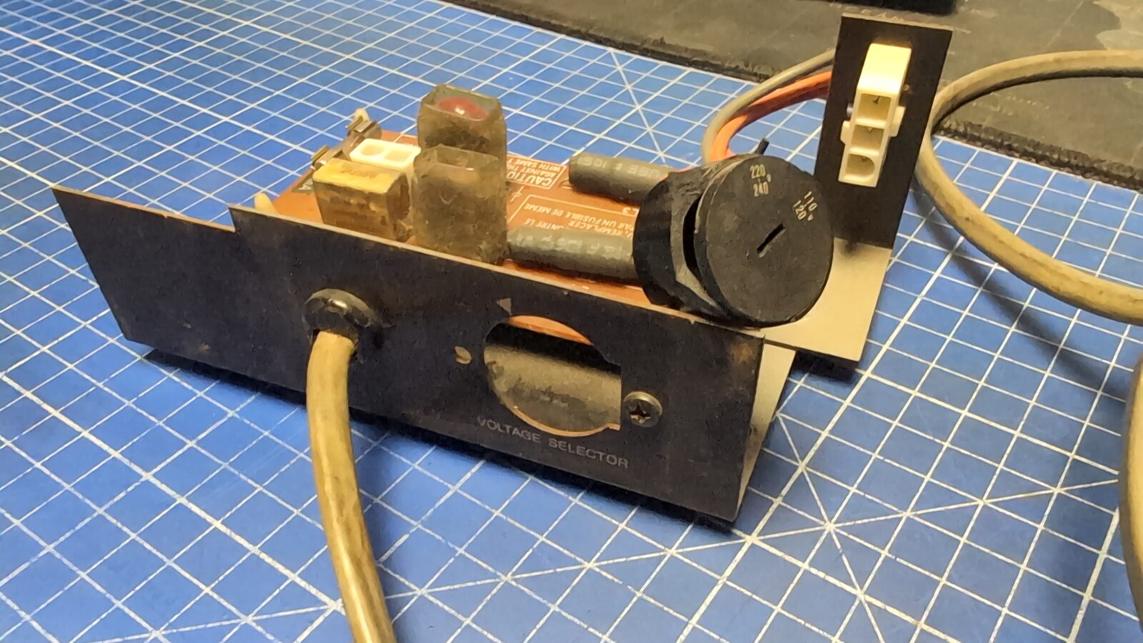
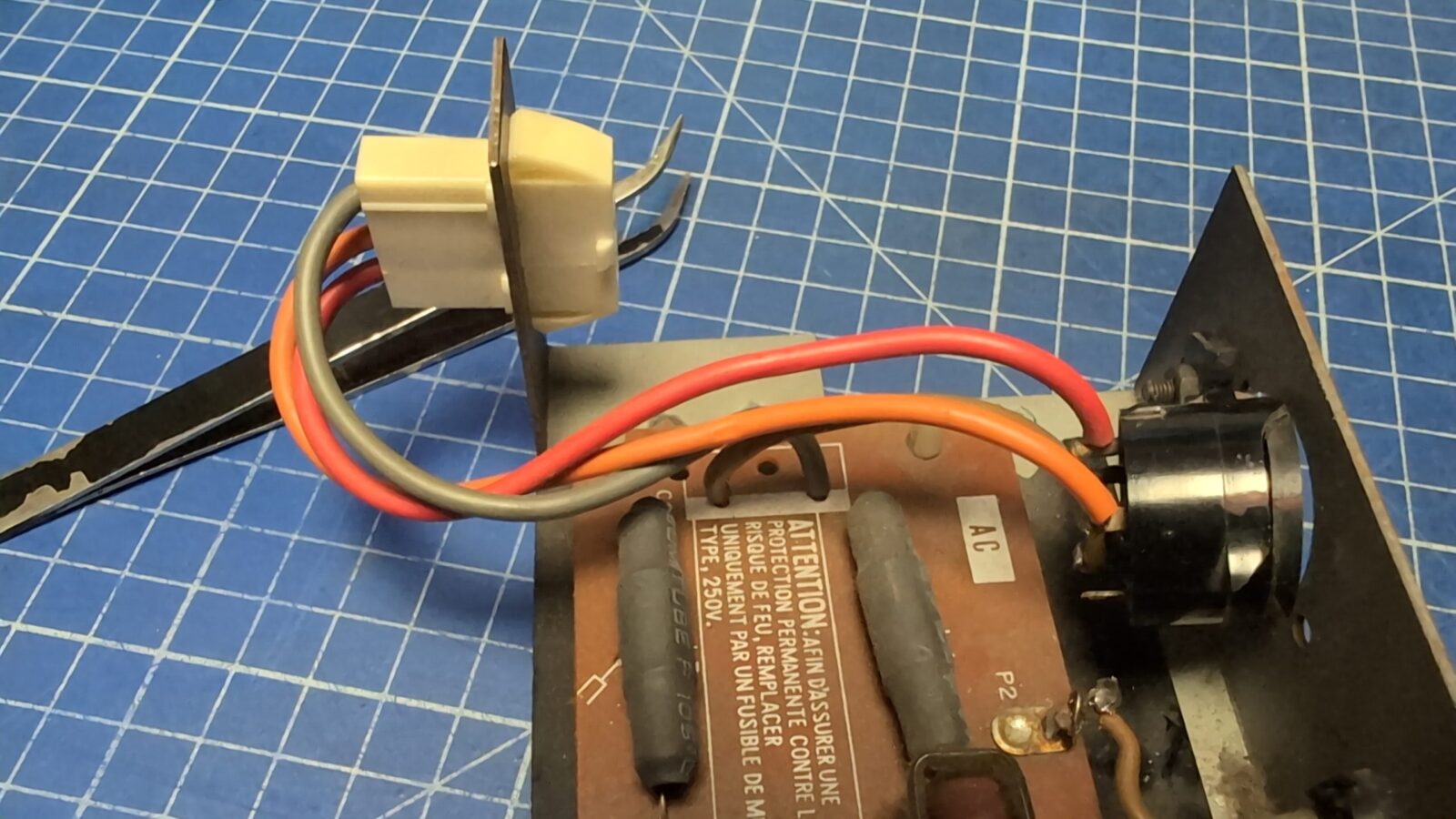
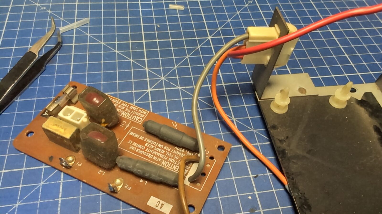
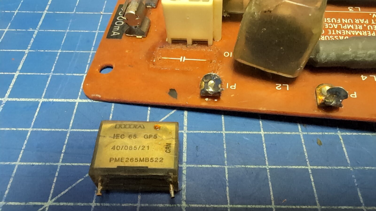
Typical issue with a broken RIFA capacitor was solved by simply replacing it.
Of course, I had to strip the paint from the bracket and repaint it. I’ve also 3D printed a small cover/shim and a dummy plug to keep things nice and cool 🙂
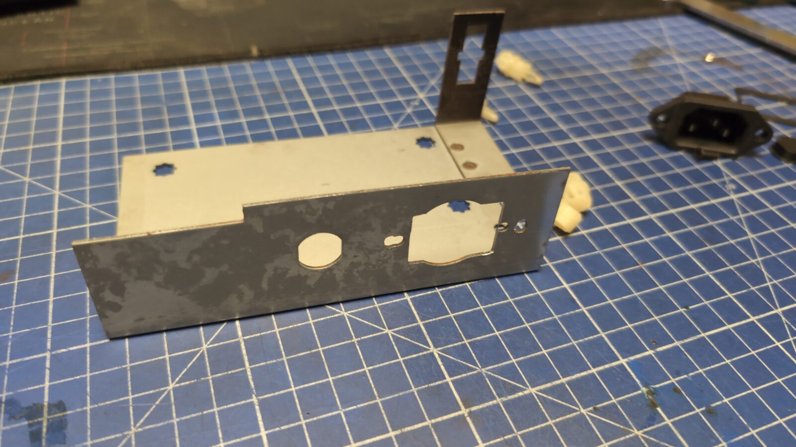
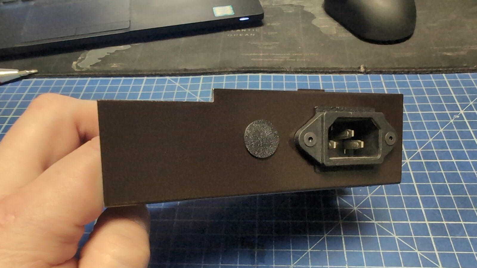
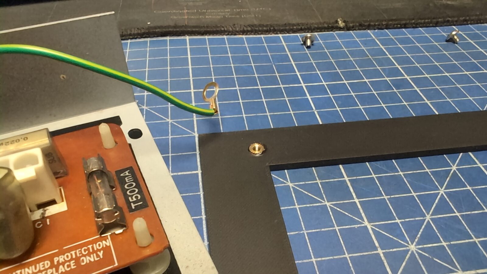
Next, because of the installed plug, the mounting points of the module were shifted. I designed a base plate for this module and installed metal inserts into it.
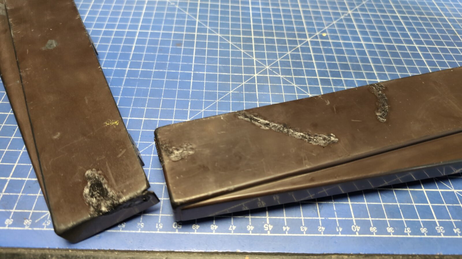
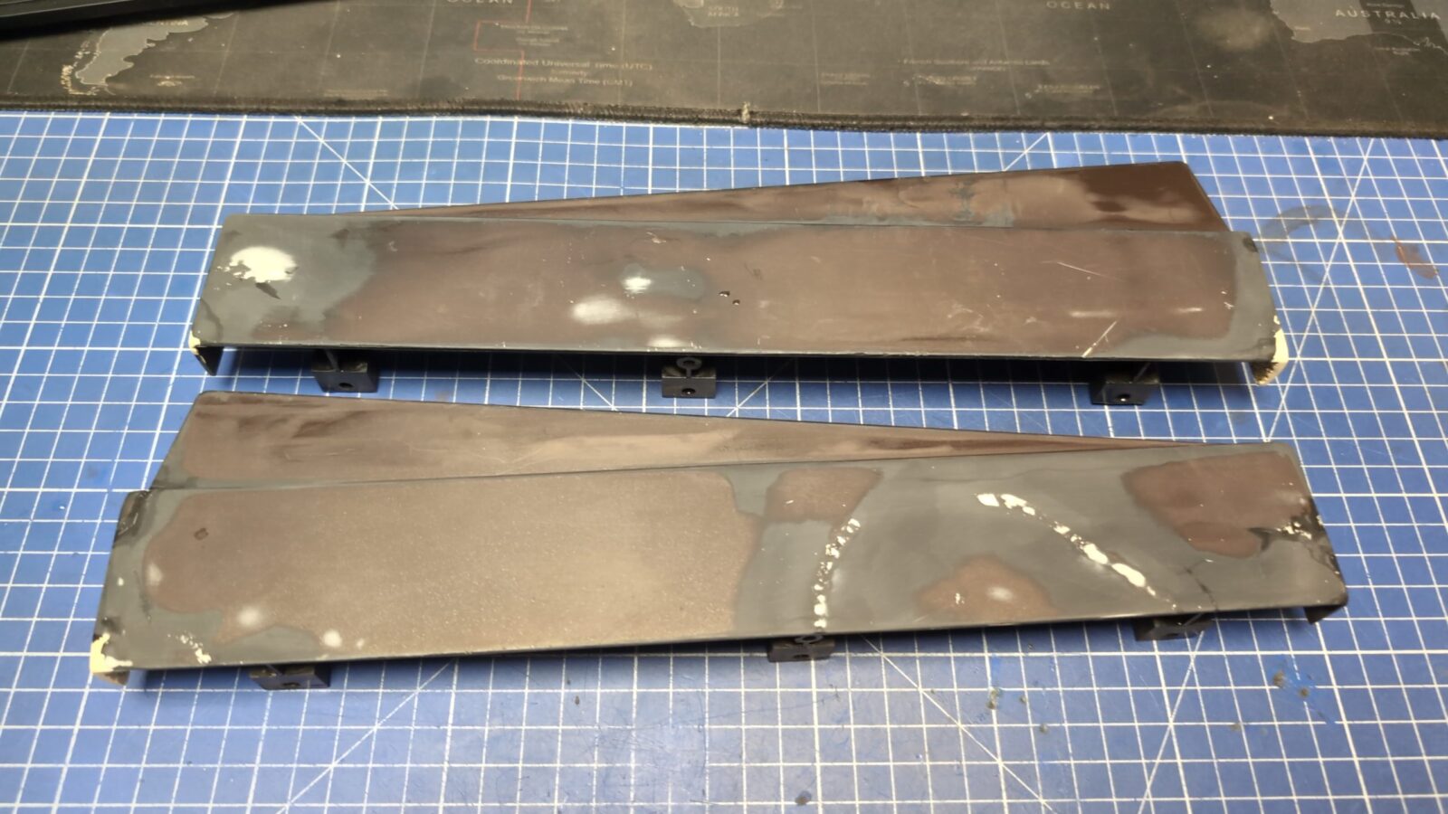
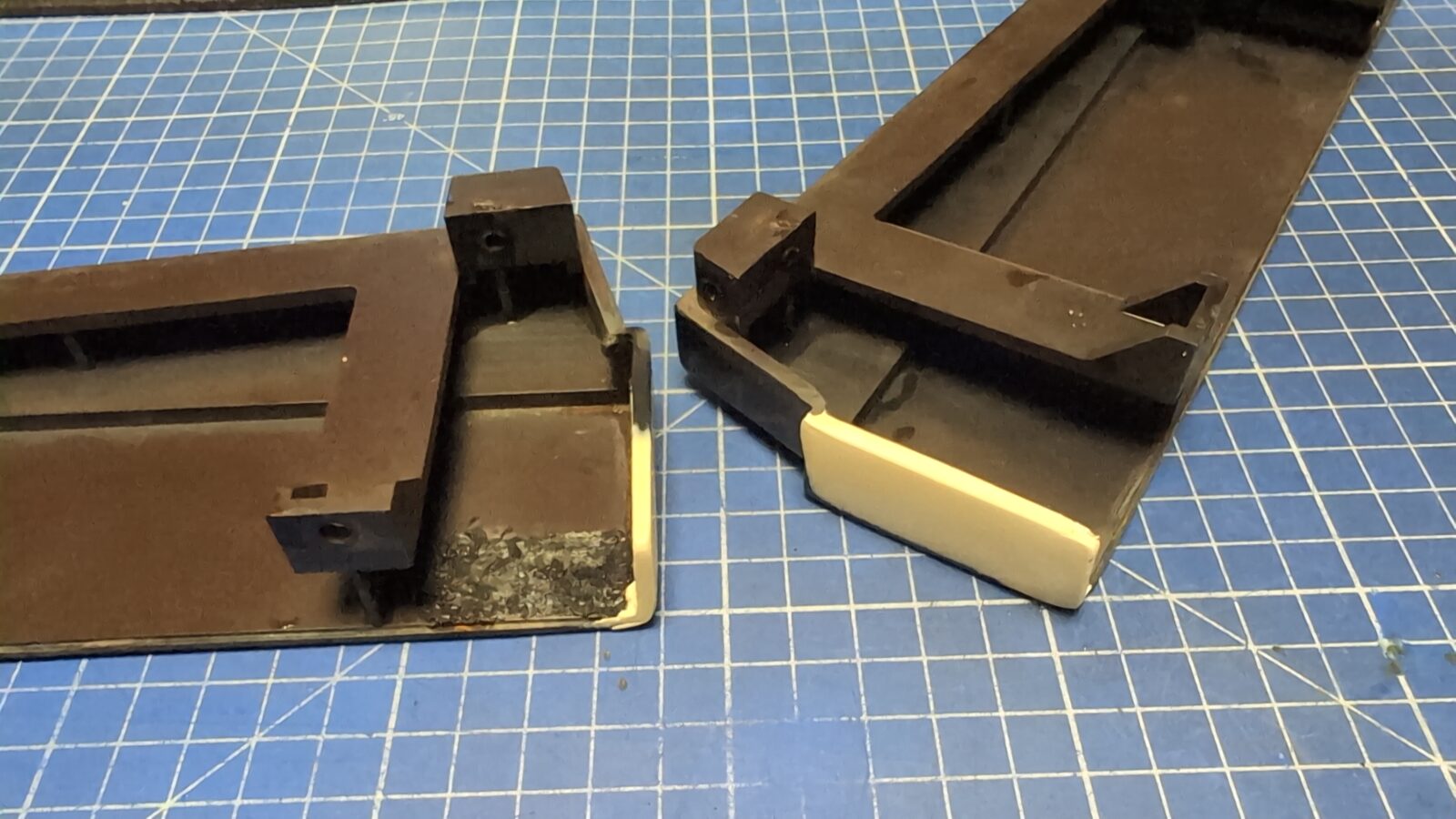
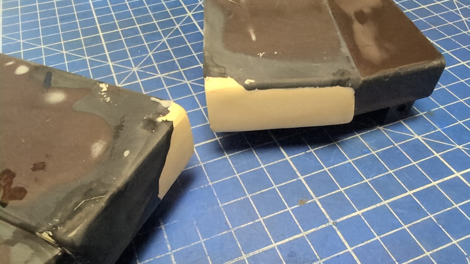
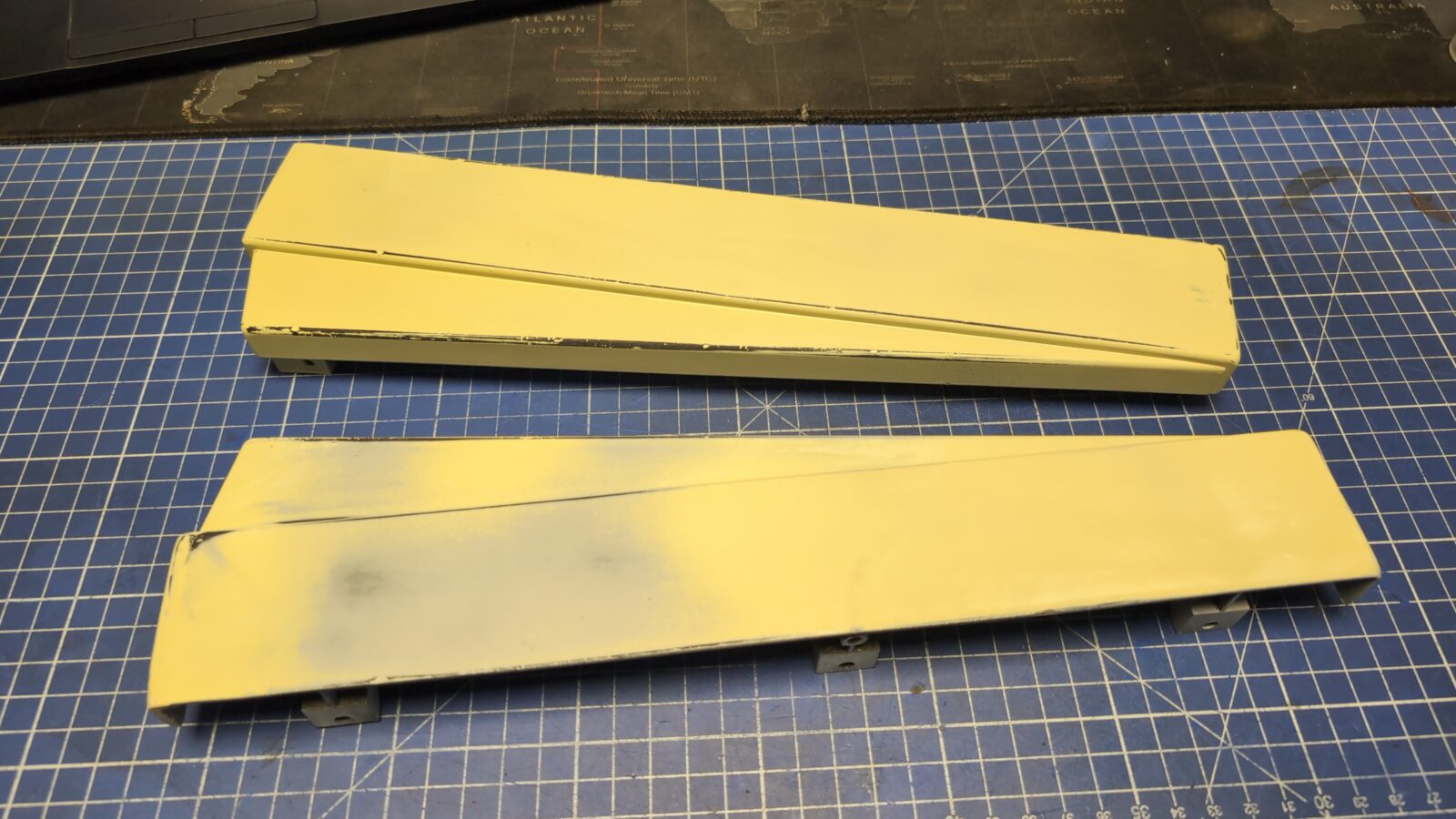
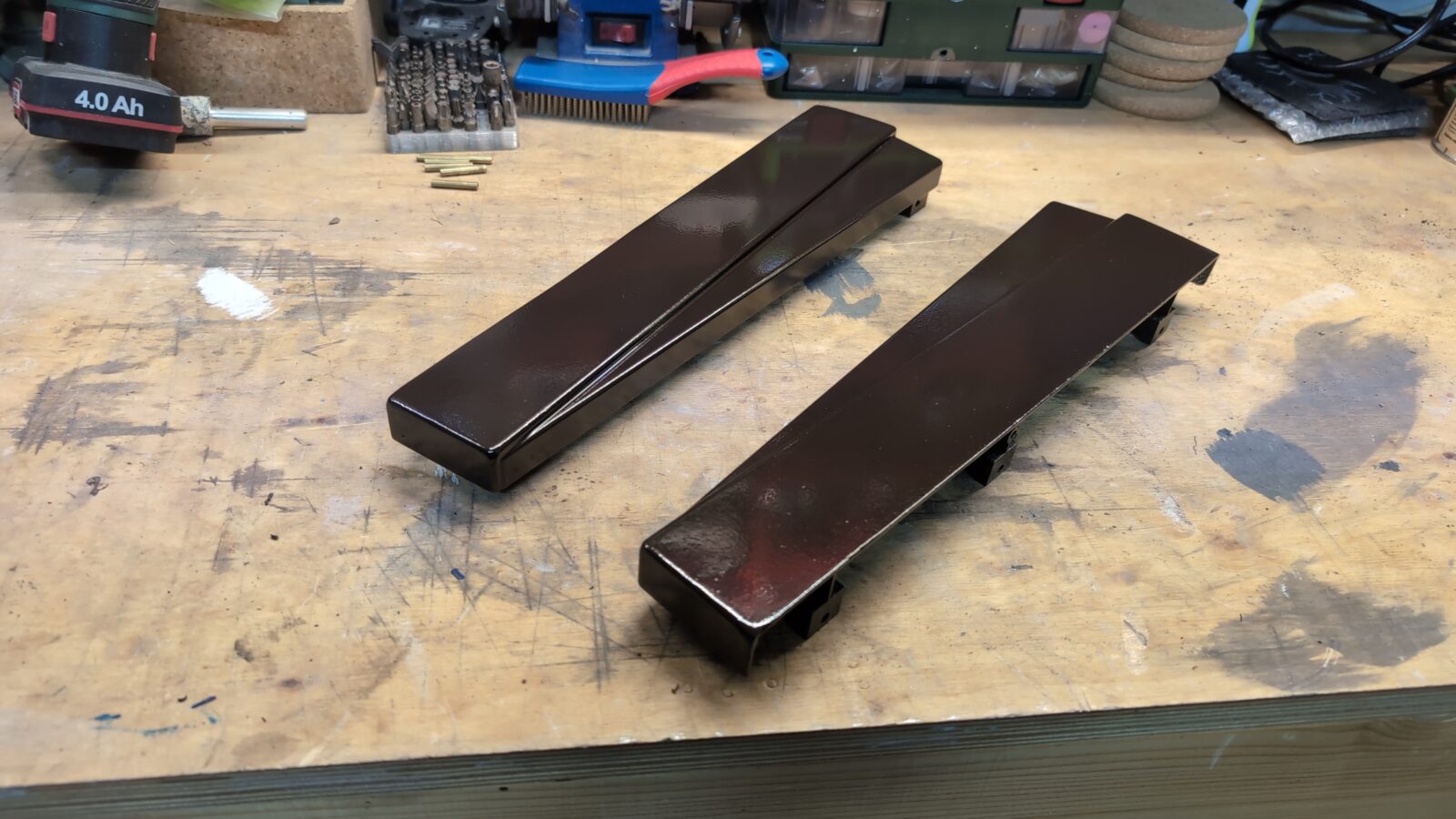
Side panels
The plastic side panels took a lot of beating and had big chunks of plastic chipped off. I’ve decided I will do a quick rebuild as I did in the past with other plastic parts.
Keyboard – follow up
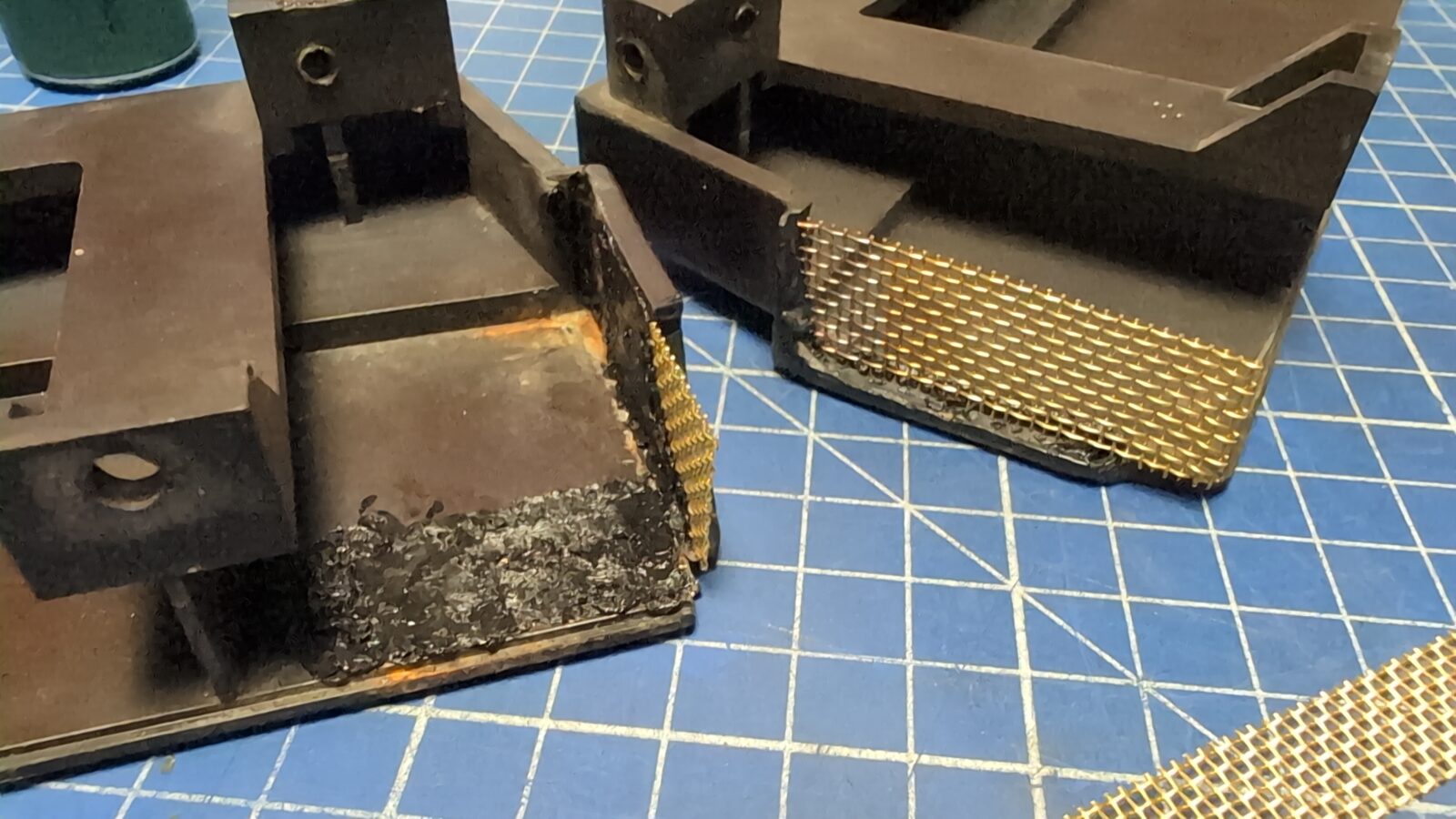
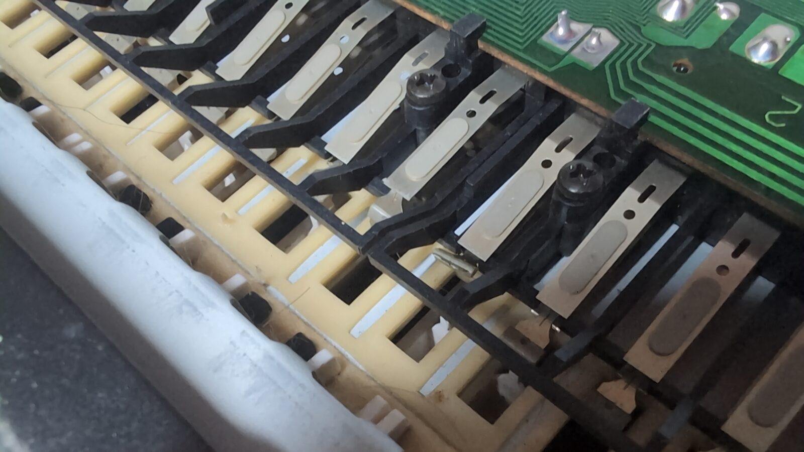
Meanwhile, Arabek managed to source the original key, and he’d sent it to me.
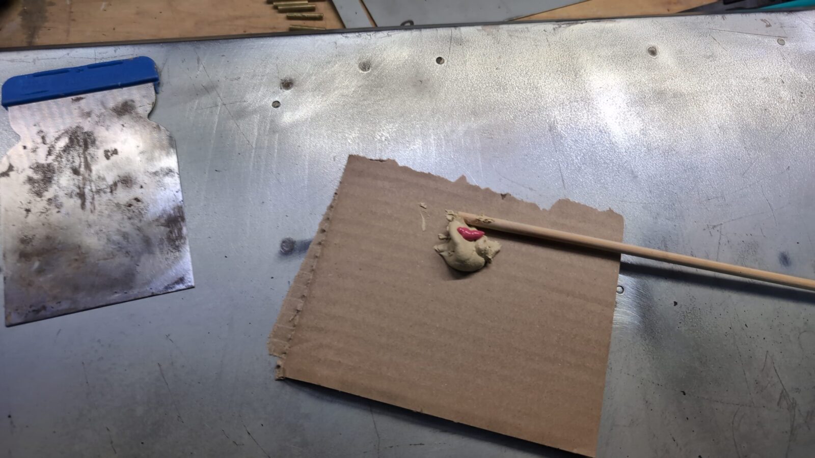
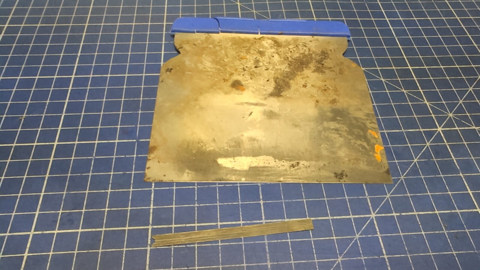
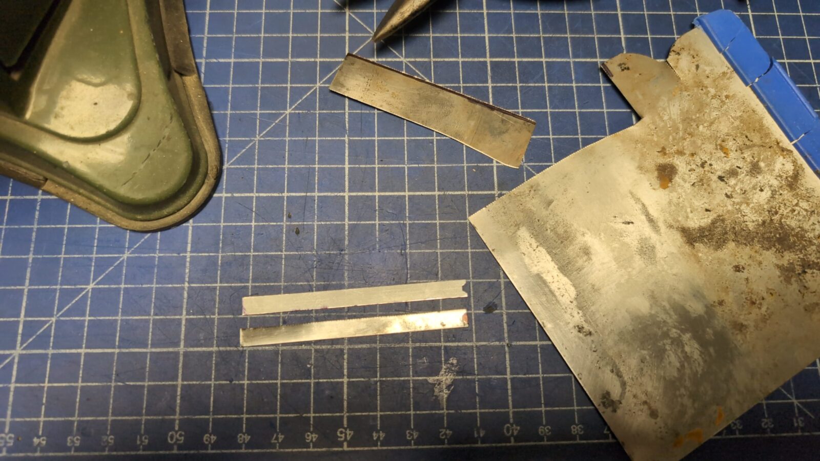
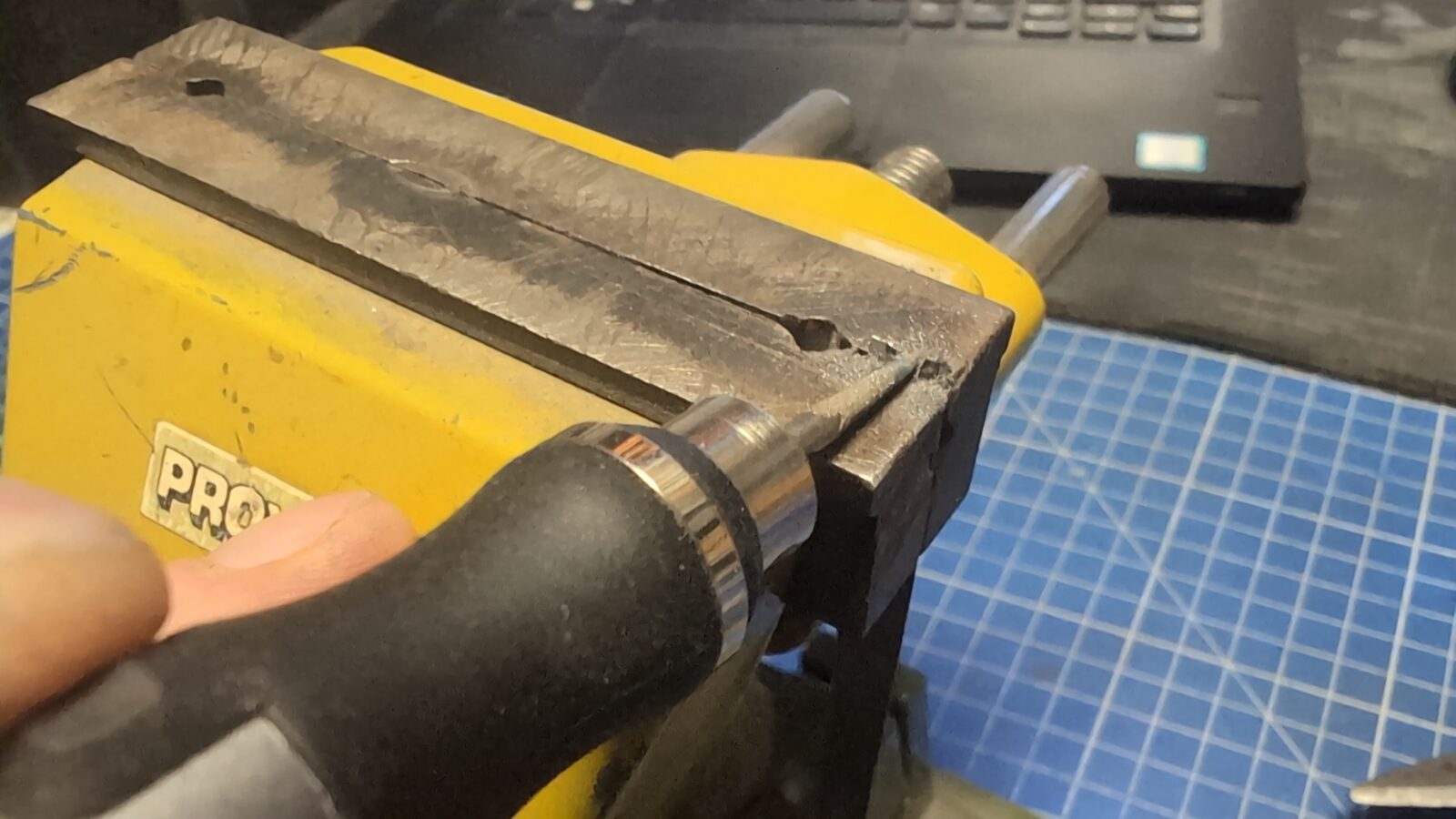
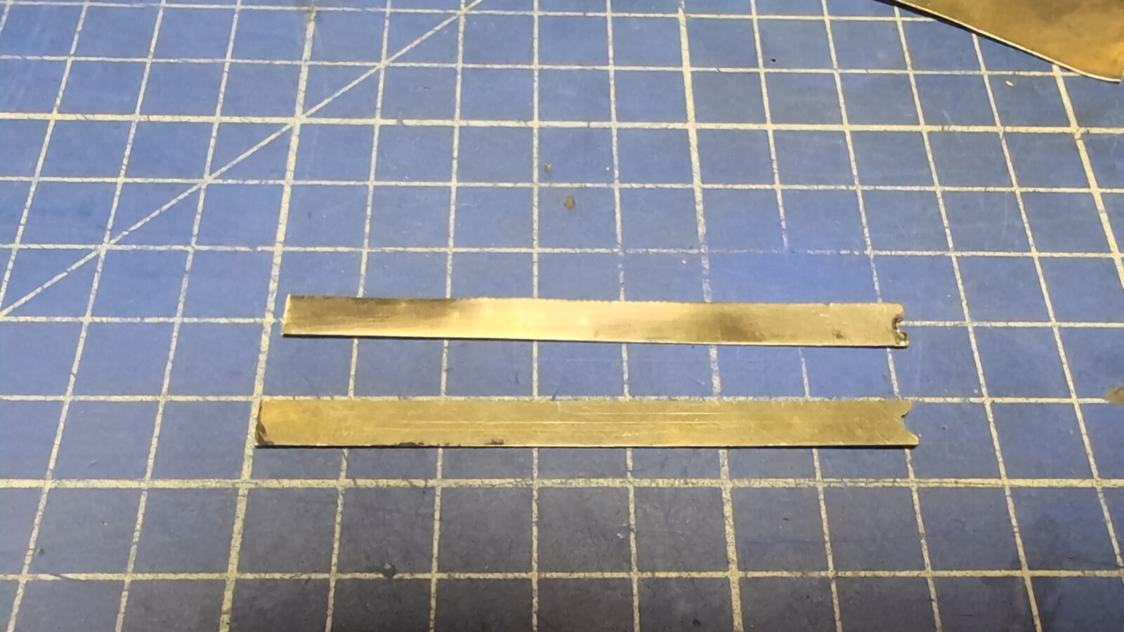
It was a complete set of keys; however, all of them were missing that springy sheet of metal. It took me a while, but finally I figured out how to sort it out. I’ve simply used an old putty knife. It nearly perfectly matches springiness and is equally thick.
In the pic below, you can see the original part at the bottom.
Now, with all keys installed, I was finally able to test if everything works aaaaaaand ….. it didn’t 🙁
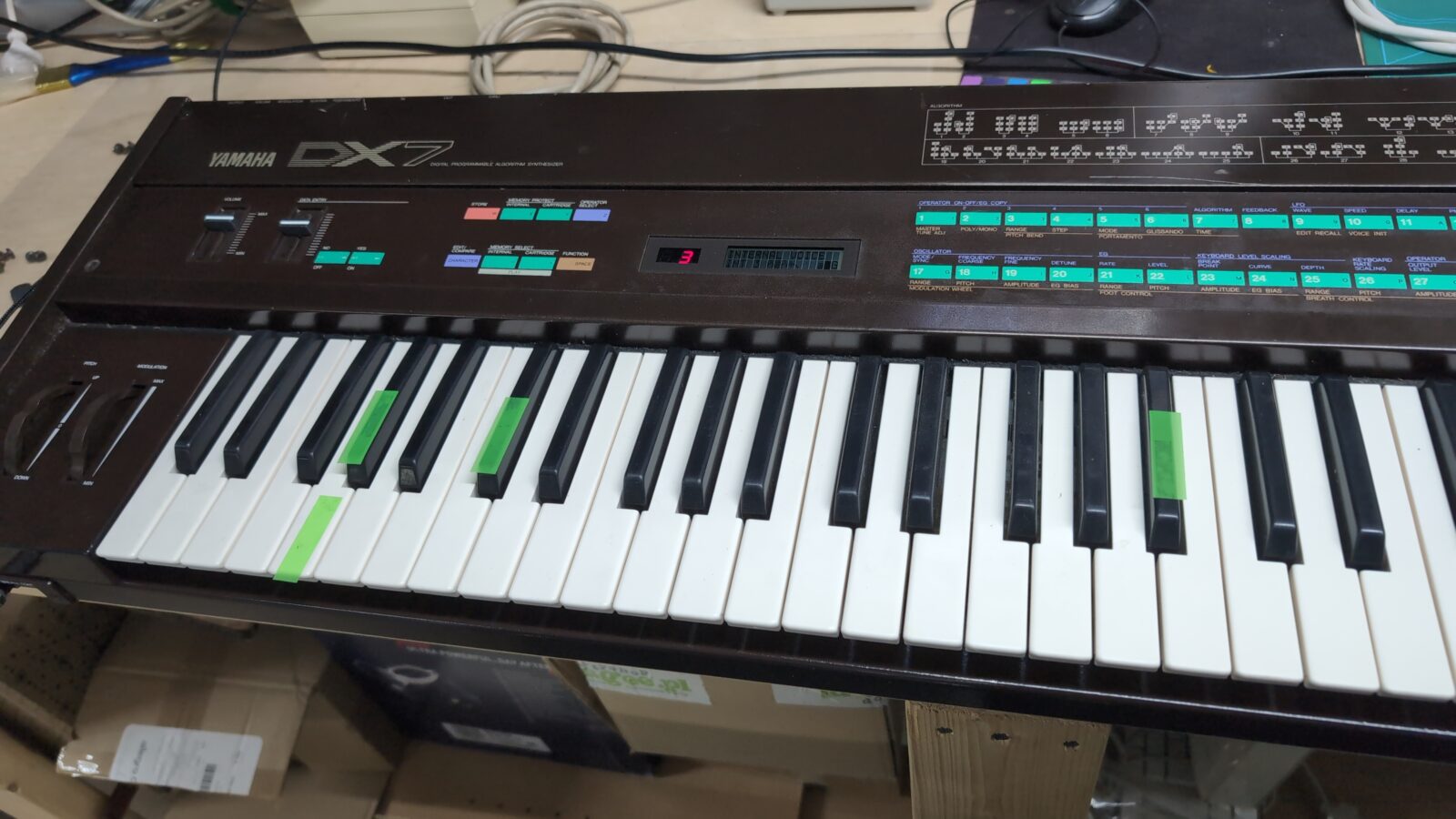
Some keys simply did’t work at all, and some only after heavily pressed.
I’ve removed the keyboard again and immediately spotted the problem. Here it is …
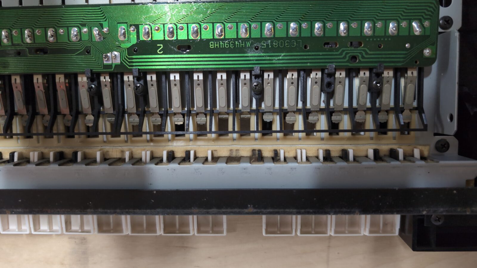
Some of the contact pads were strongly bent. All I had to do was straighten them all up, which nicely fixed the problem.
Top panel
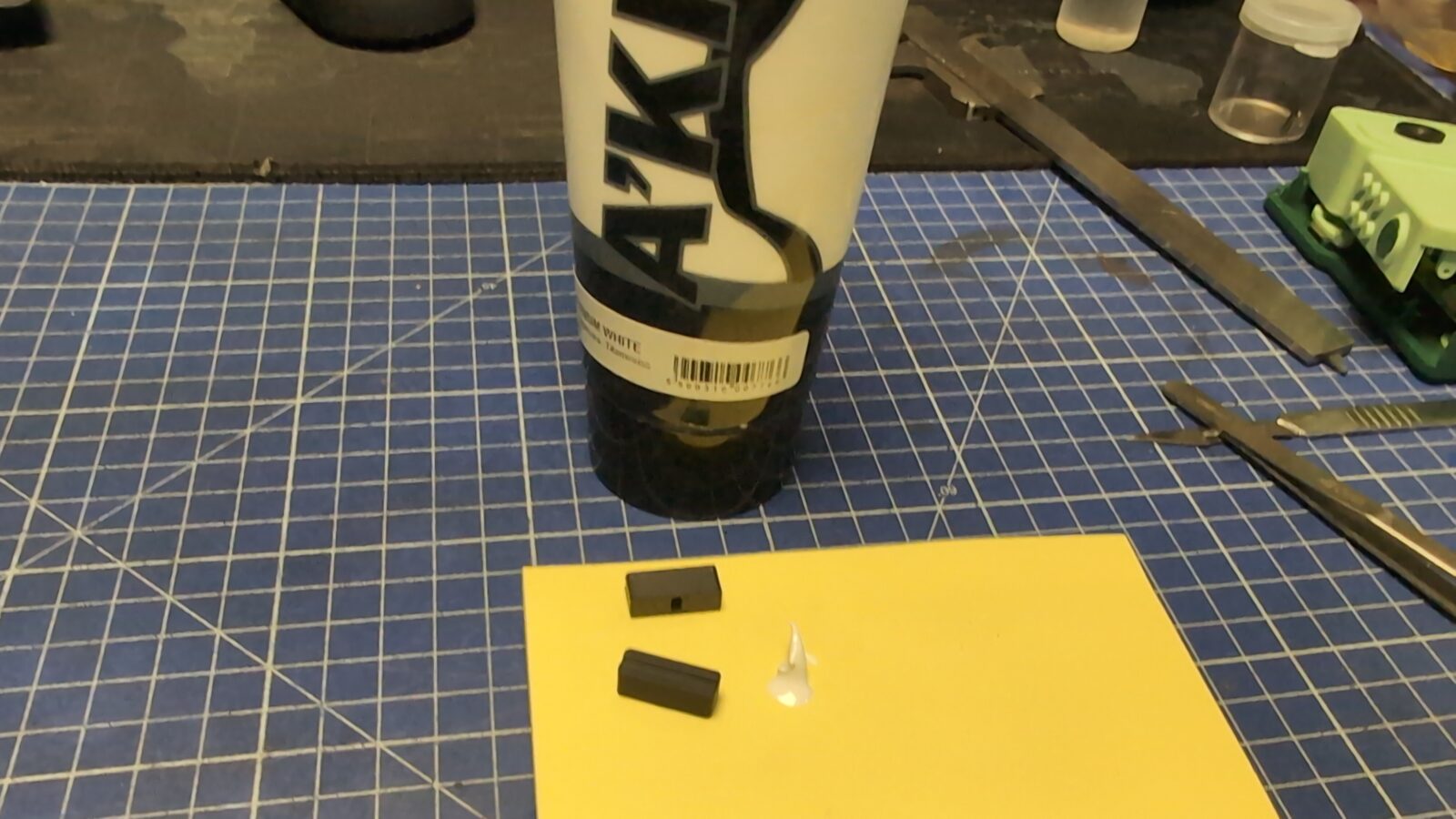
I didn’t plan to rebuild the top panel from scratch, as this would require tons of modeling time, the time that I didn’t have too much for this project. Instead, I limited myself to thorough cleaning. Still, there was one more bit left to do – missing lever covers.
Again, 3D printer to the rescue. A quick modeling session based on the Internet pics resulted in nicely 3D printed caps.
I’ve finished it with a bit of white acrylic paste.
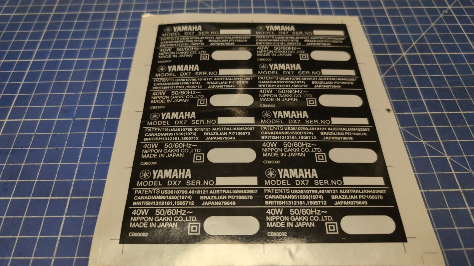
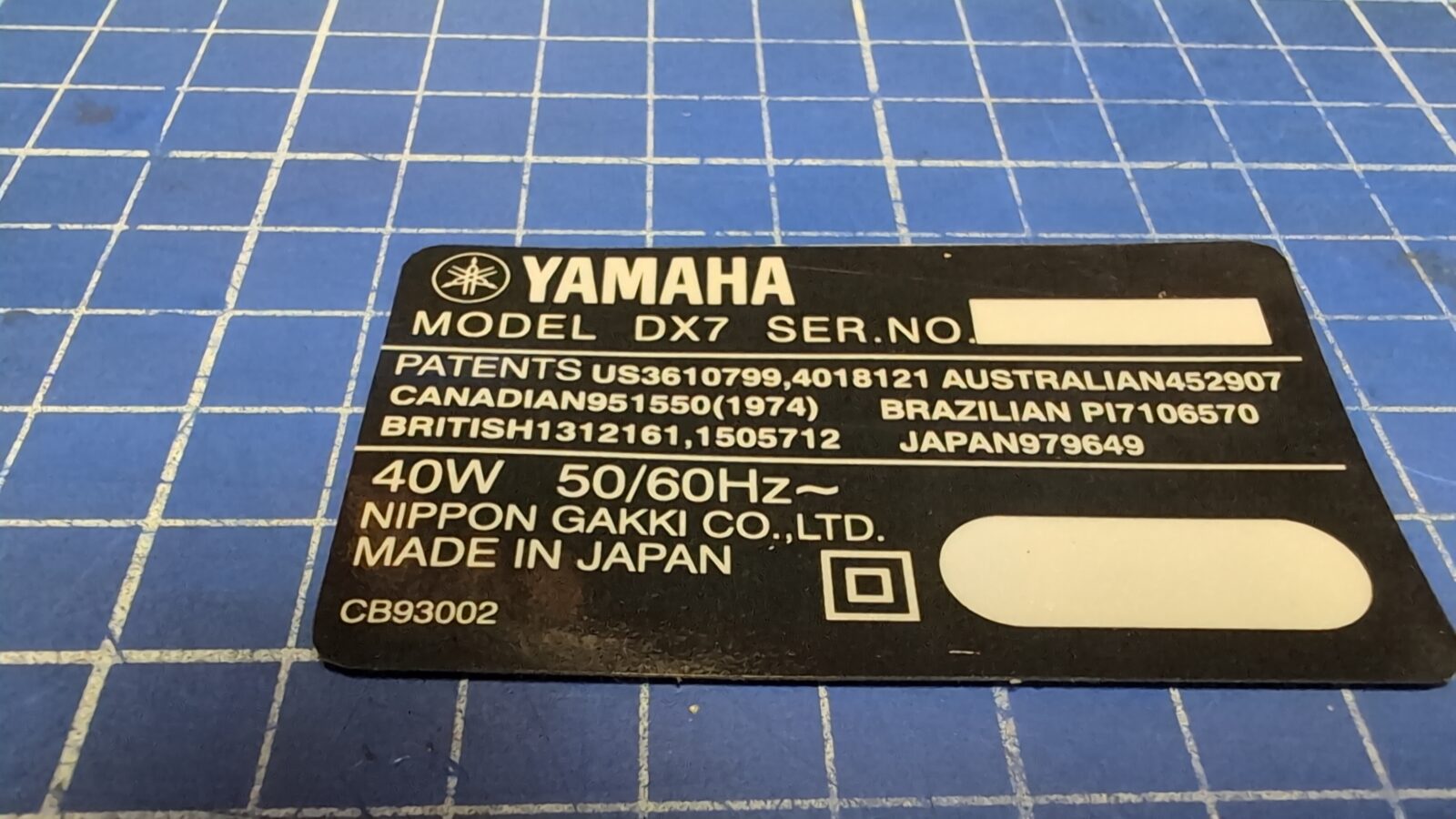
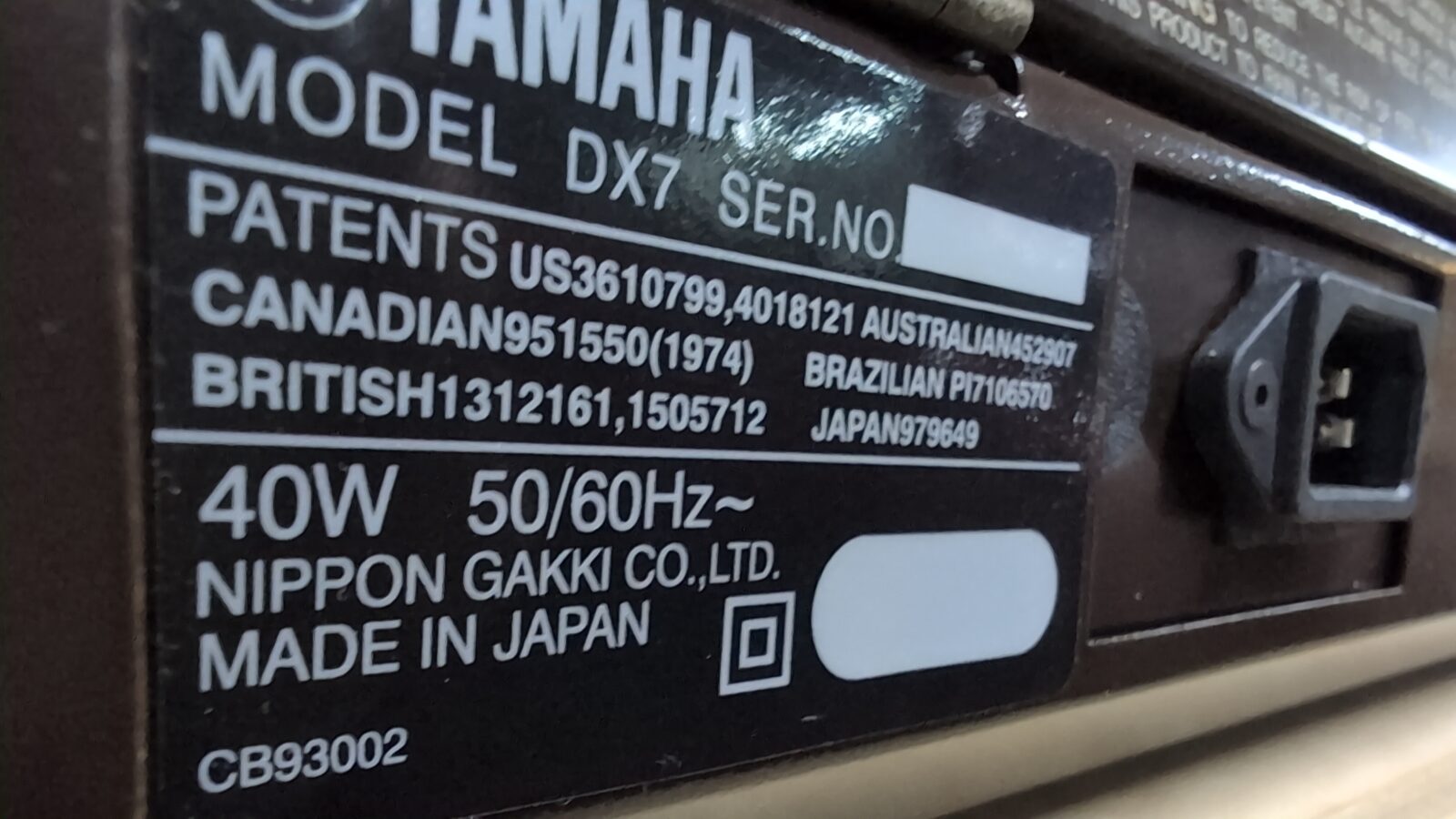
Sticker
The very last thing left was a sticker on the back. I’ve asked Chris of Retroklinika if he could manufacture a similar sticker, and he, as usual, agreed YAY! 😀
The end
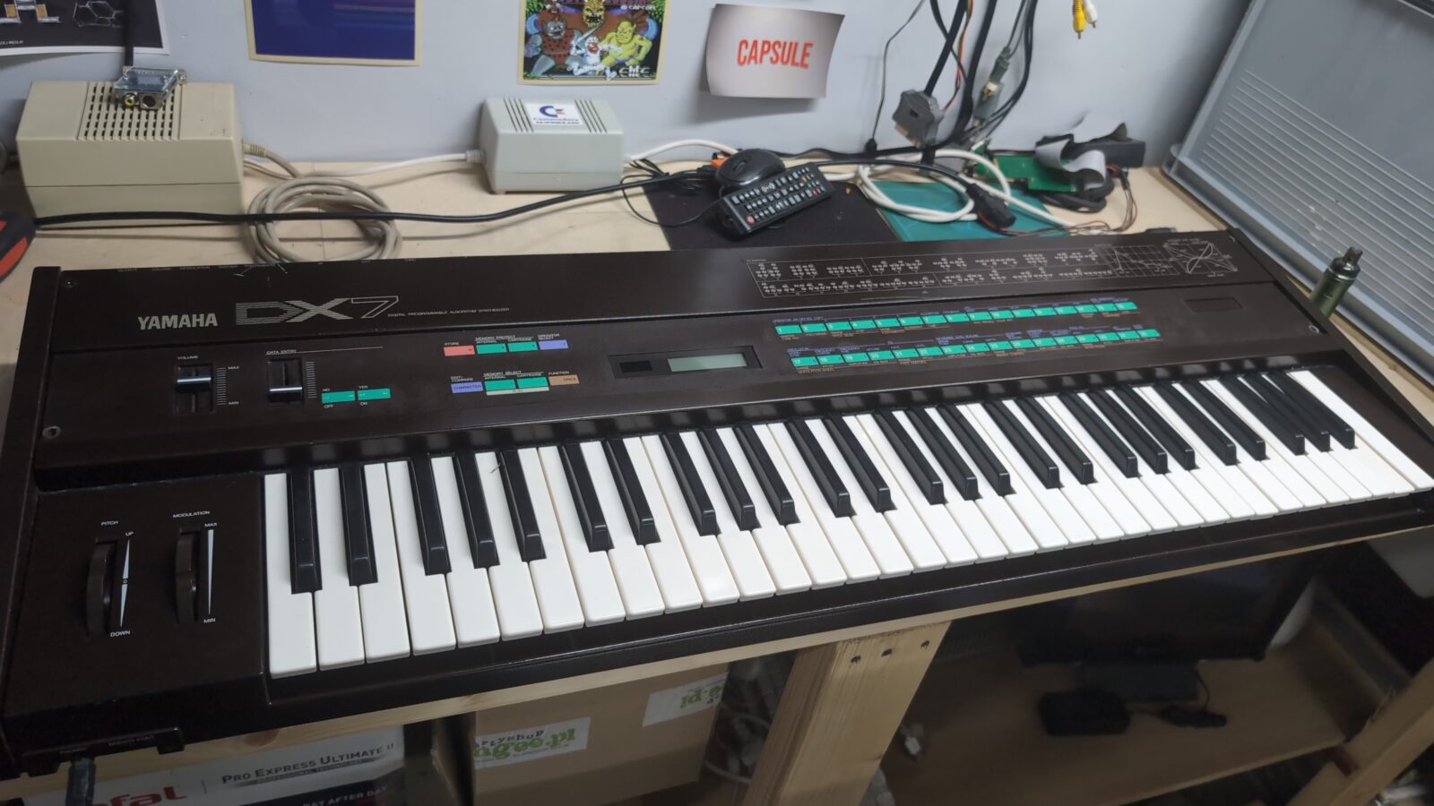
This is it. The machine works nicely, although I only tested basic features as I am not a synthesizer expert 🙂
Outro
All promised 3D printing files and other stuff that were used in this particular project -> HERE
See you in the next post 😀

What’s the role of an RTC in a synthesizer? Isn’t that battery used for keeping the settings in memory when tha device is turned off?
EDIT: I found the schematics online and, indeed, there is no RTC in the synth. The battery (which is a rechargeable one! Beware!) is tied to three 5118 RAM chips. See https://manualmachine.com/html/c1/c1b9/c1b92dd76db2364c93b9c0a79004d36ad4fc24600a960d4299587ee2668cdd38/img-3-9vrDjfYbrV.png
Good point! I guess, I named it RTC bat out of pure habit. Way too many computers on my bench and only one (this exact one) synthesizer 😀