… or I just saved a PET because I have enough of Mac fixing :>
Intro
… so the saved PETs be like …

Rrrrite … This one was waiting in a queue for a long time. Actually, double-time in a weird sense. First, it waited nearly a year for me to start working on it, and then had to wait again for me to write a blog post about it 🙂
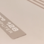
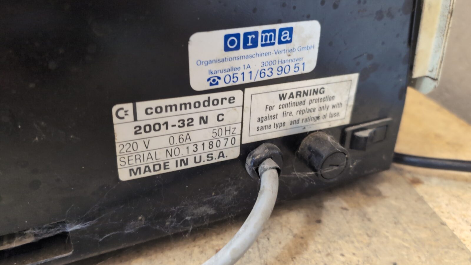
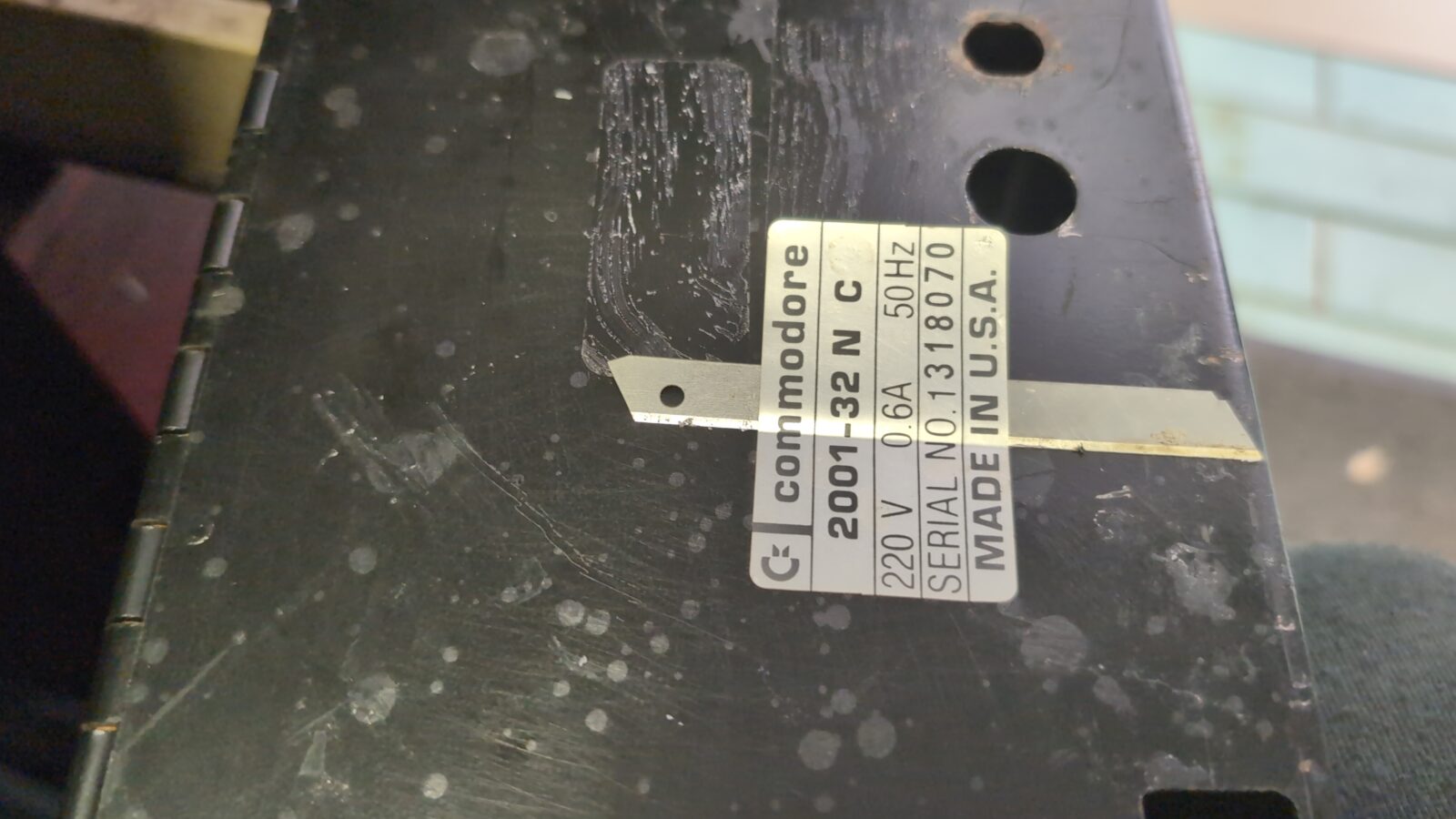
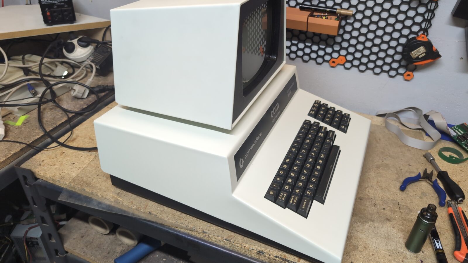
The computer I am talking about is the CBM Commodore 3032 from 1979, which is sort of a successor to the famous Commodore PET, although lots of people still call it PET.
The story behind it is quite usual. This time, Zoltar X of the New Generation demoscene group asked me if it is actually fixable. At first, I was a bit skeptical, but then I was like, hey! I can try, as I’ve never worked on any of those machines. Damn, it is always like that … lol.
Overview of the disaster
Turns out that the machine belonged to one of the professors of the University of Szczecin. Obviously, once it became obsolete, it was thrown into a cellar and waited there.
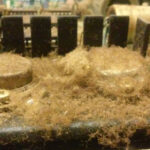
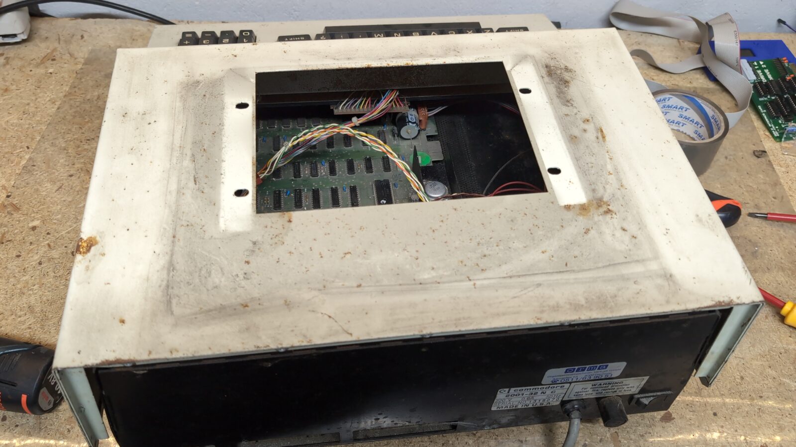
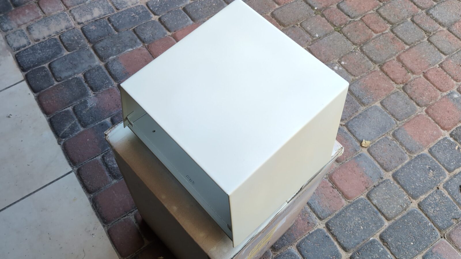
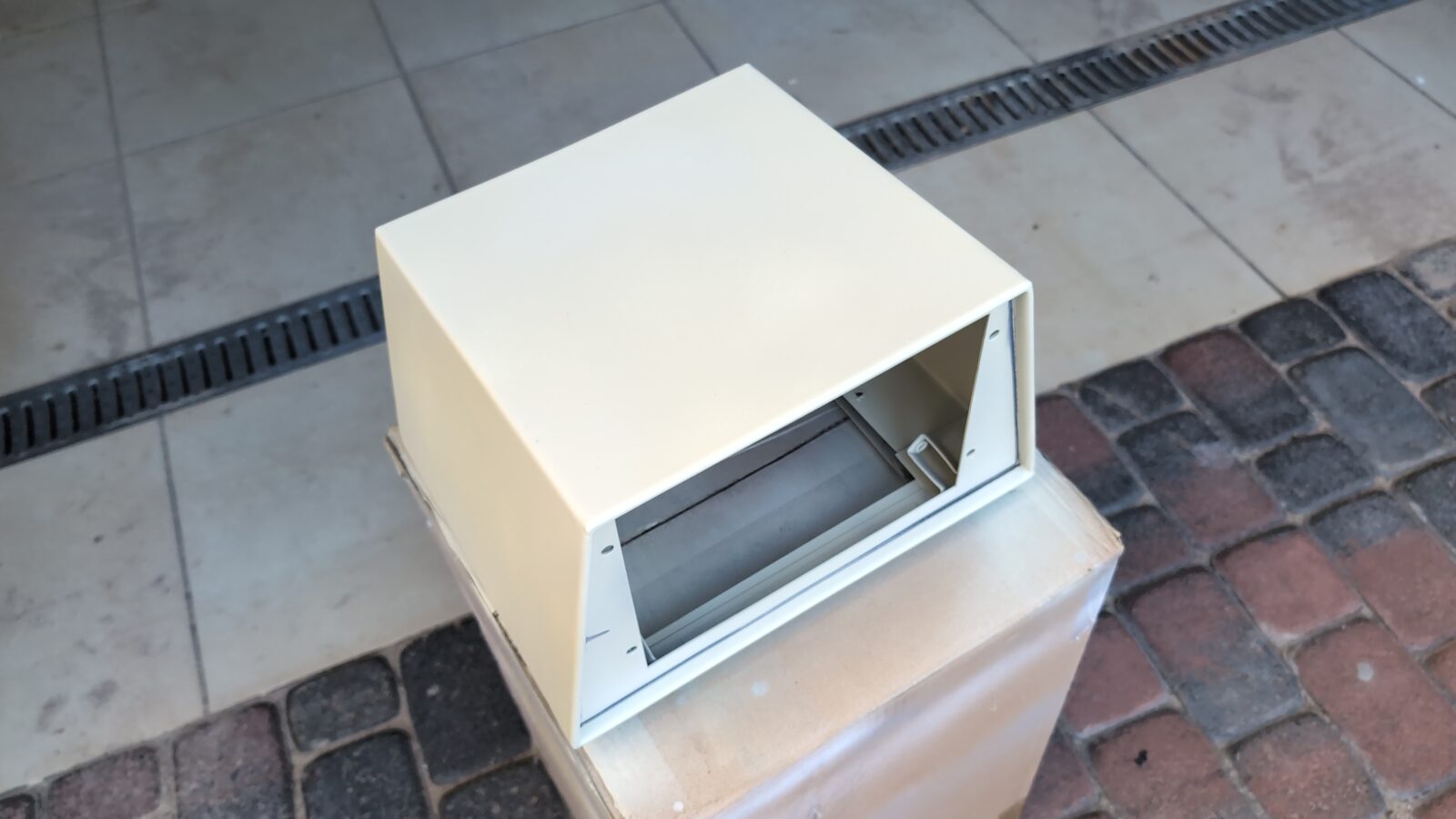
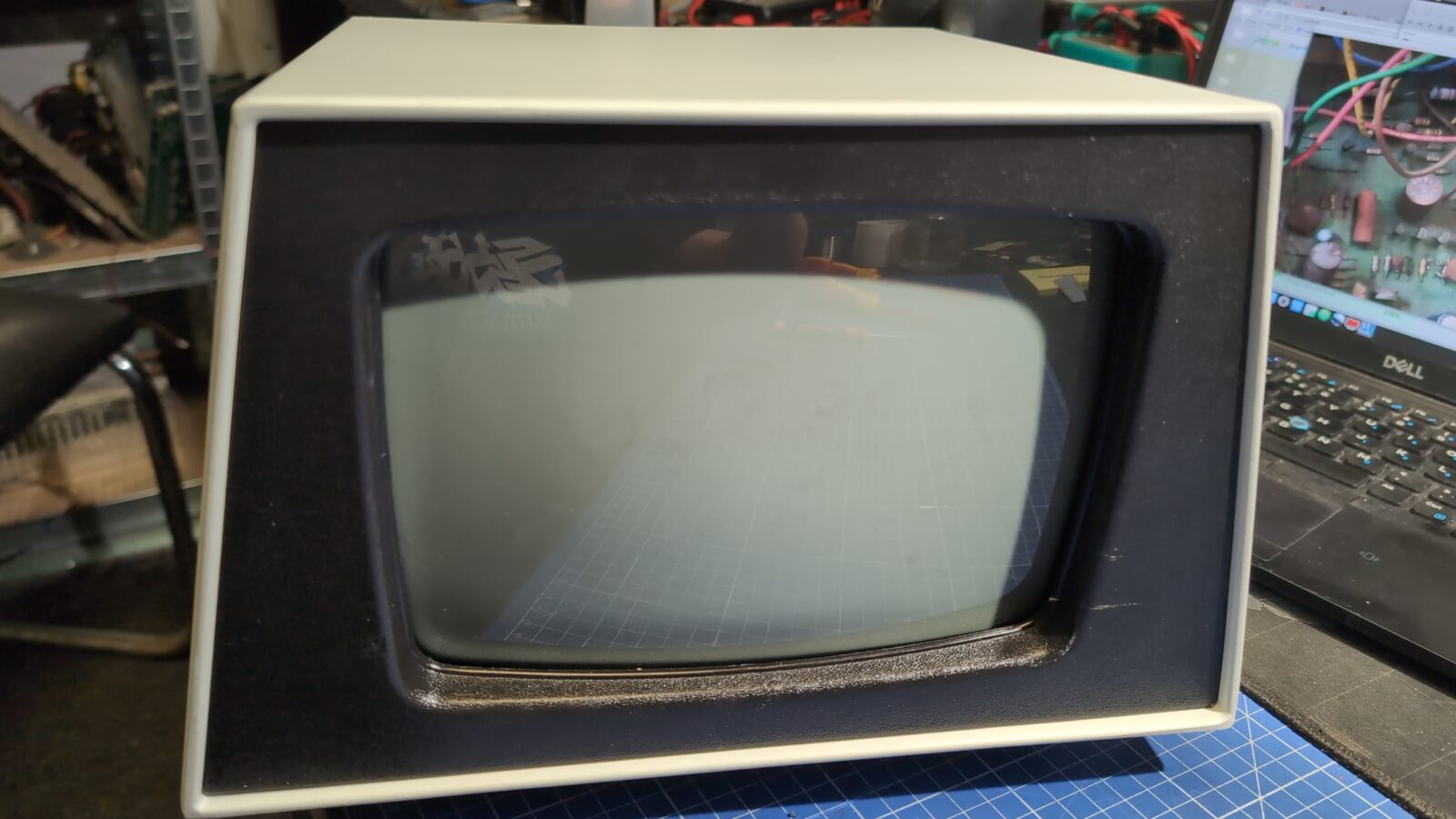
Here is how it looked once it was delivered to me.
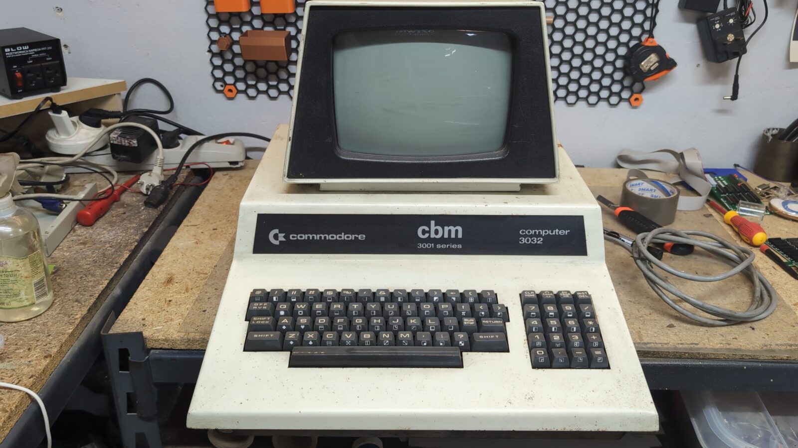
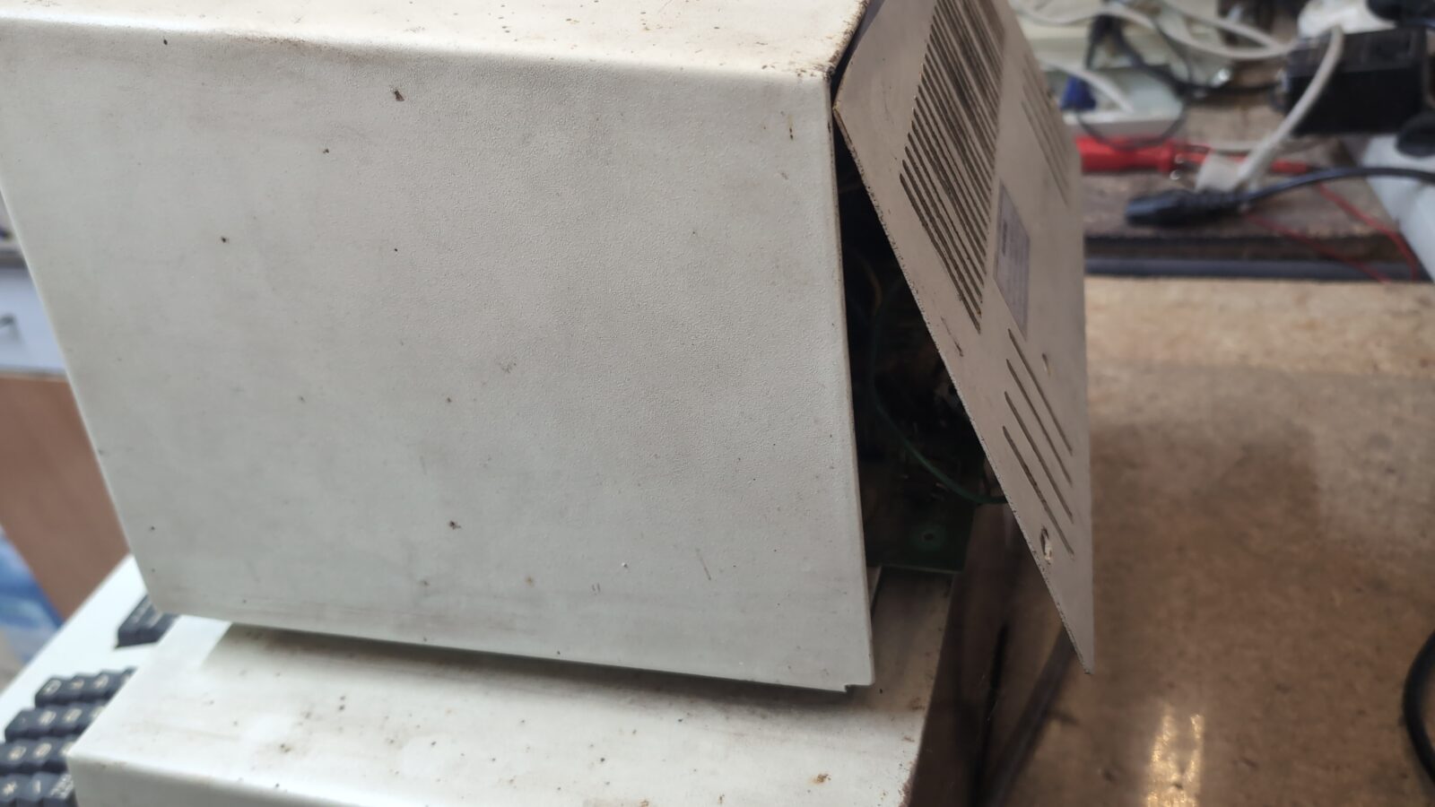
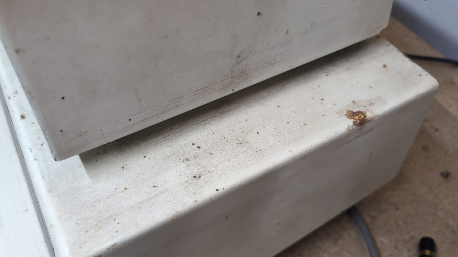
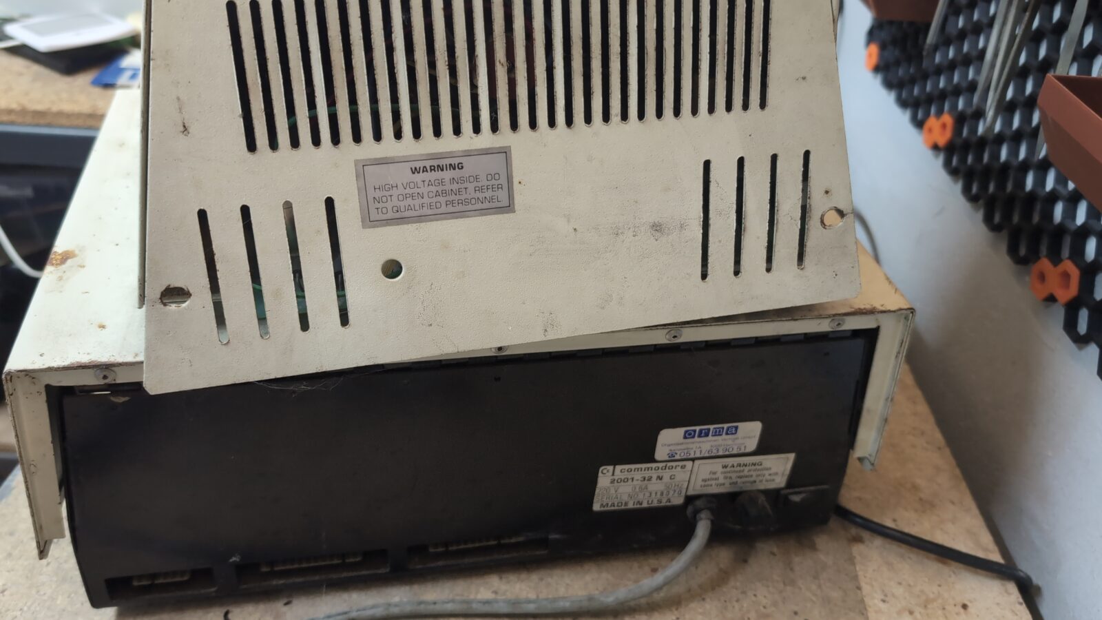
The usual stuff … rust, cut wires, dirt.
Disassembly
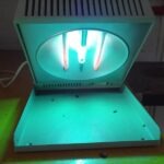
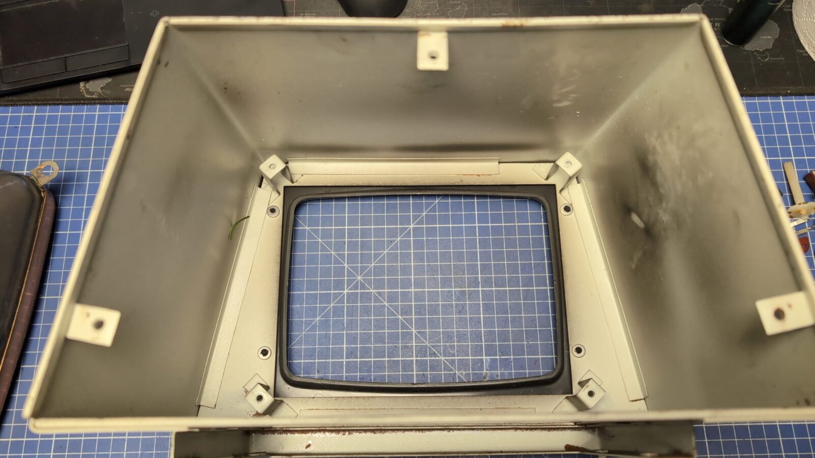
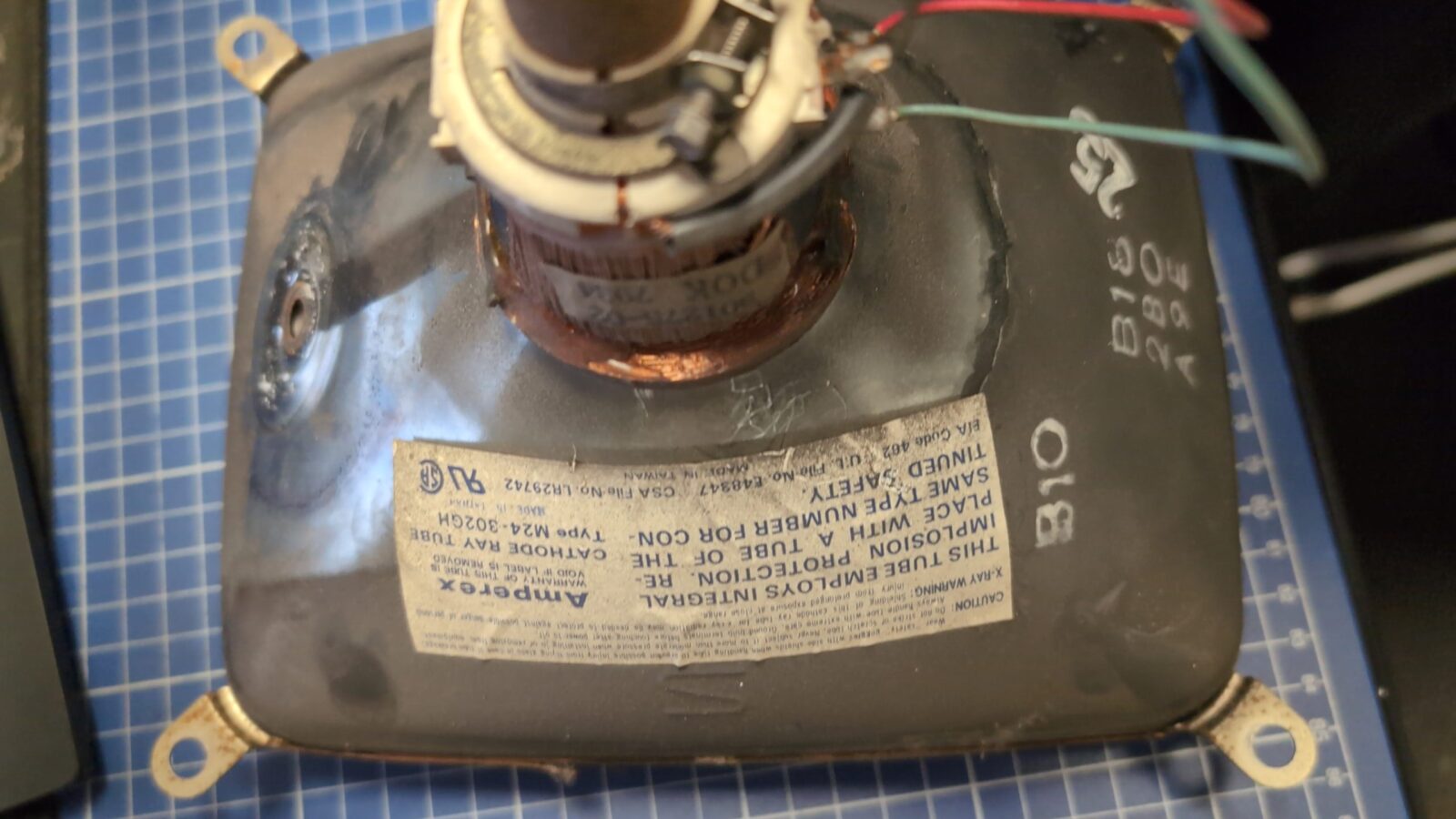
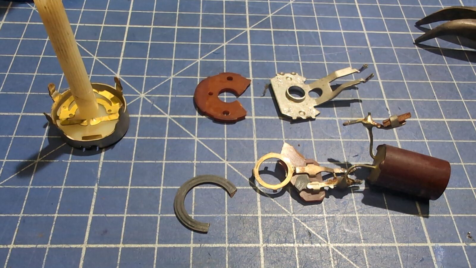
I started with the CRT, which has its own housing. It became obvious in the first minute why CRT doesn’t light up … it was simply disconnected.
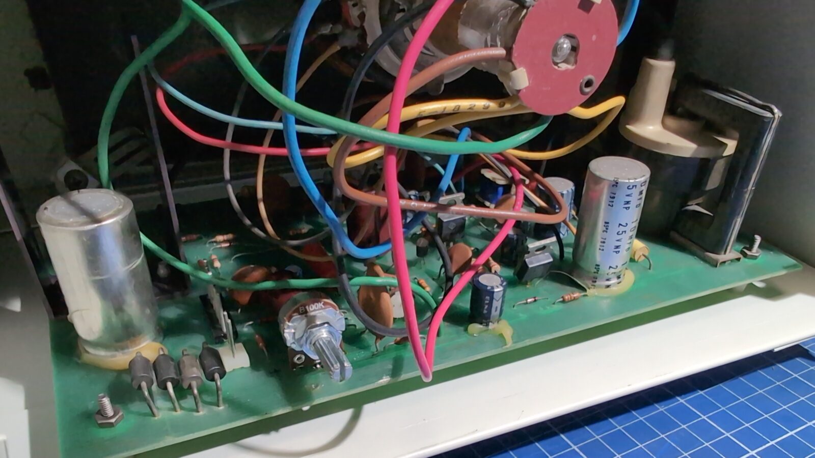
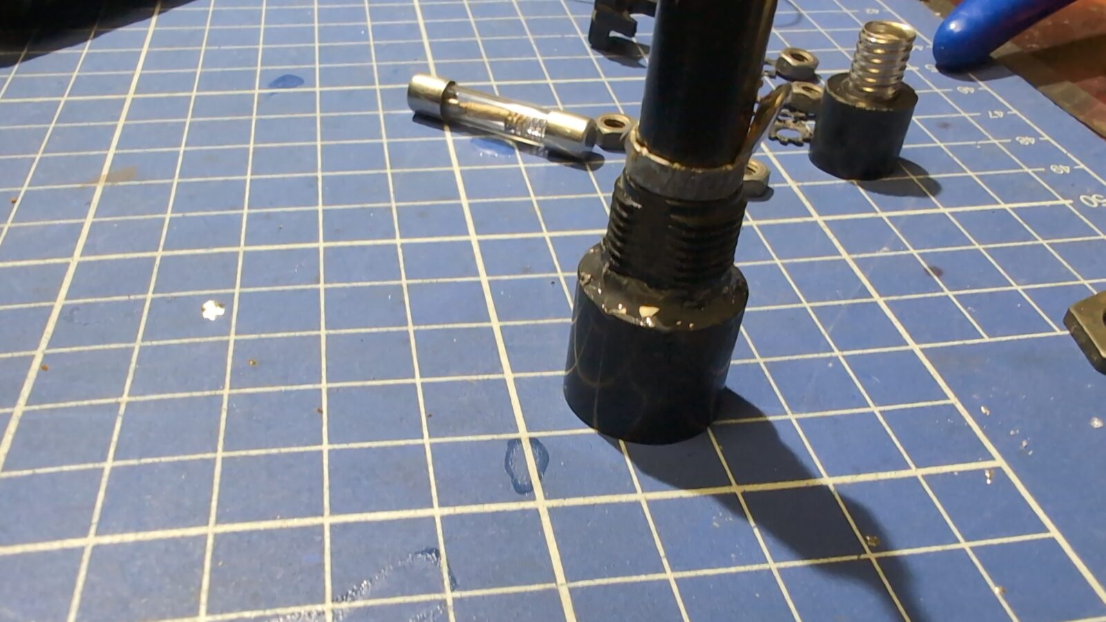
Also, the brightness POT took a lot of beating.
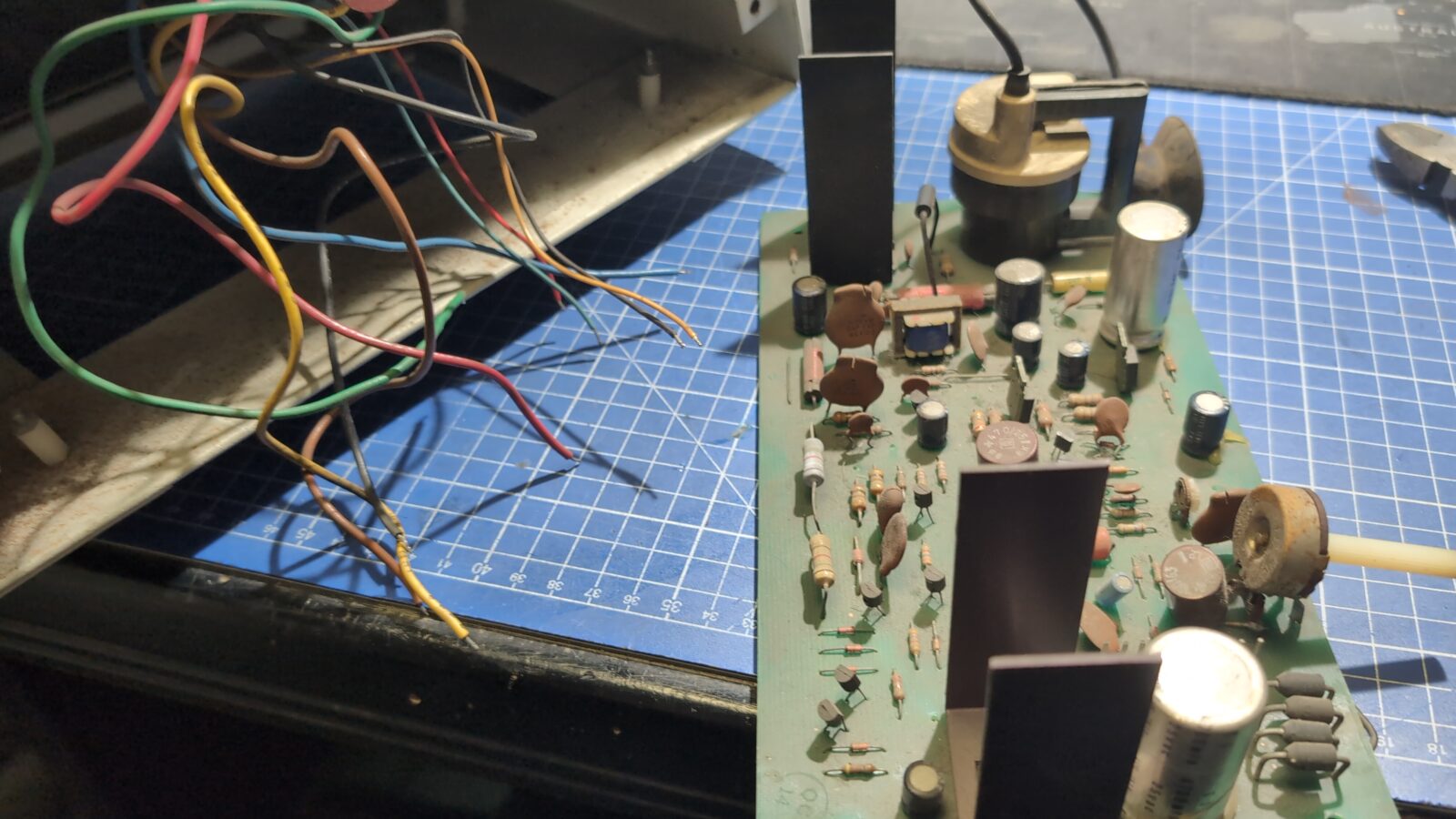
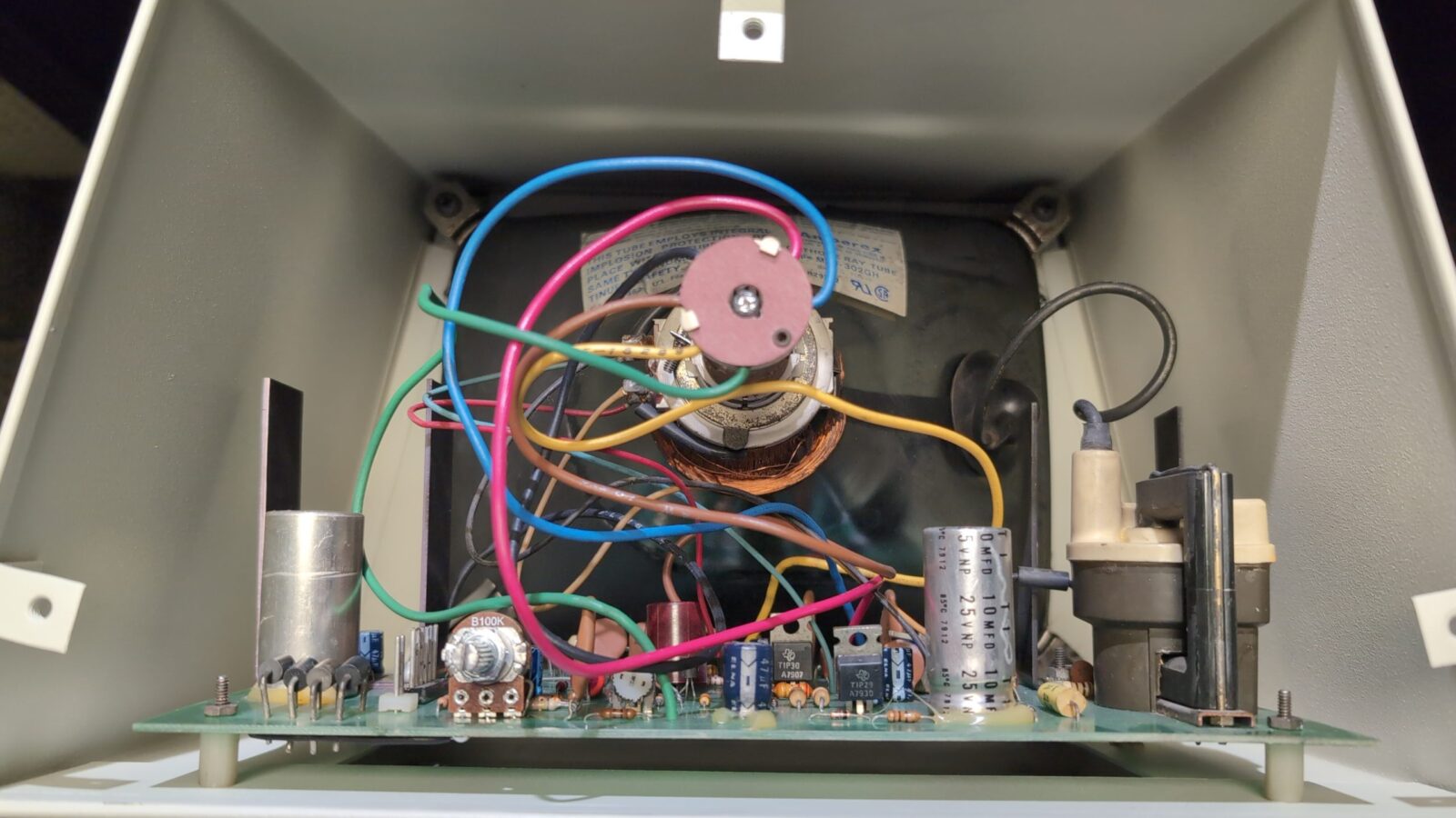
Since all the yoke wires are all soldered to the PCB, I took some time to make pics to not mess up when reassembling it all.
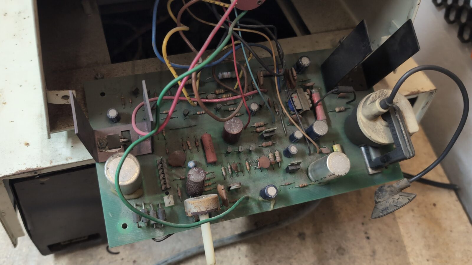
CRT circuit fixes
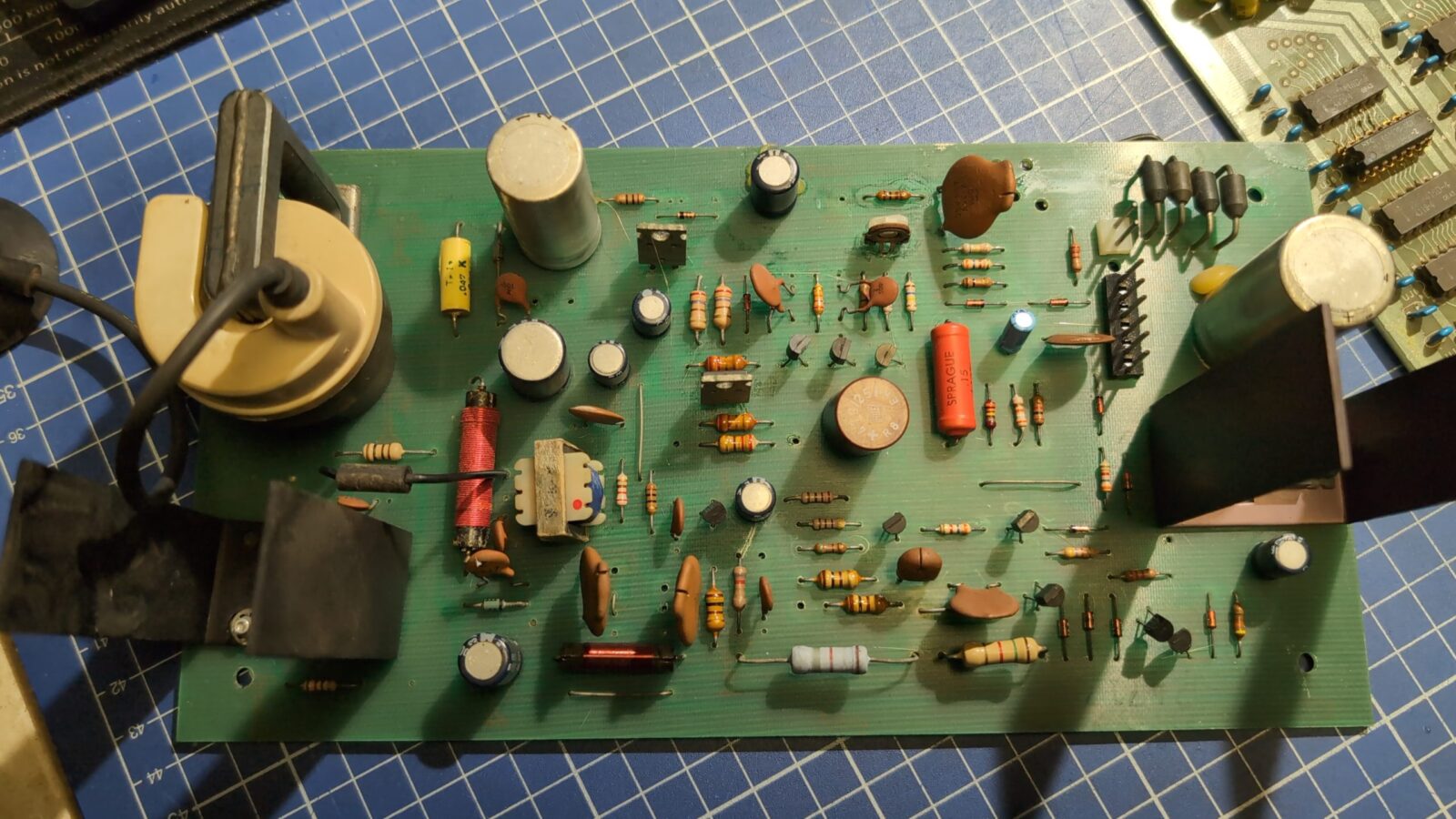
Now I could desolder all the wires and inspect the PCB
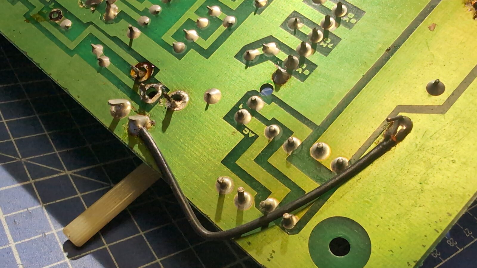
A perfect cold joint was spotted immediately.
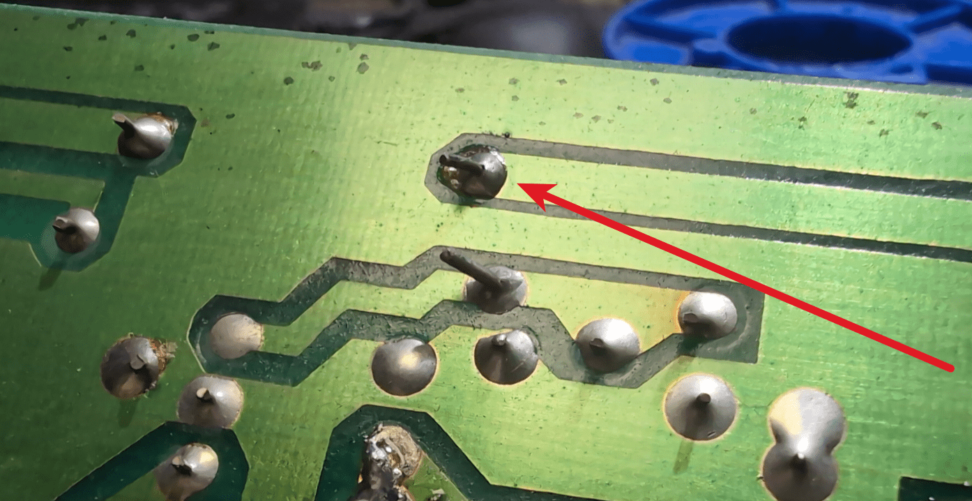
Some weird soldering, too.
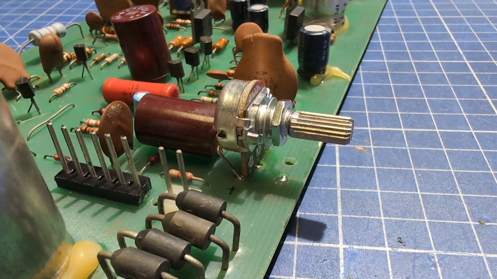
I’ve started with the POT issue :>
I wanted to simply replace it with a new one, but there was no visible info on its original resistance values.
I first resorted to schematics, which showed it as a 100k Ohm POT. I’ve uploaded schematics HERE.
To confirm that, I simply measured it.
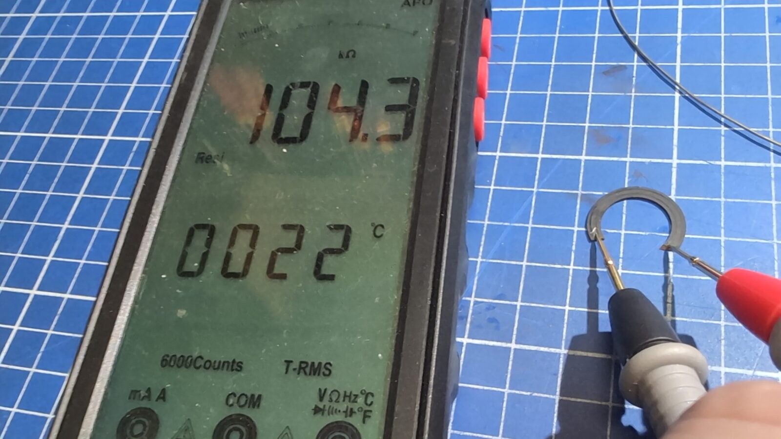
Then, I’ve cleaned the PCB and replaced the POT with a fresh one.
The rest of the issues were dealt with later.
Disassembly of the main part
I moved on to further disassembly of the computer.
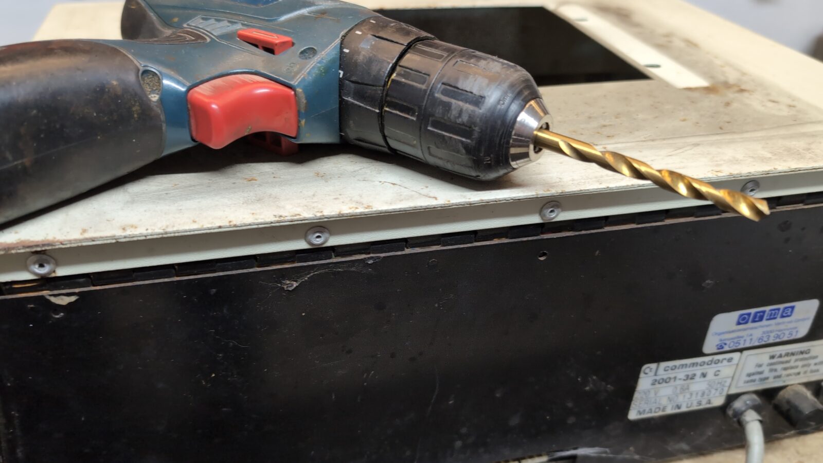
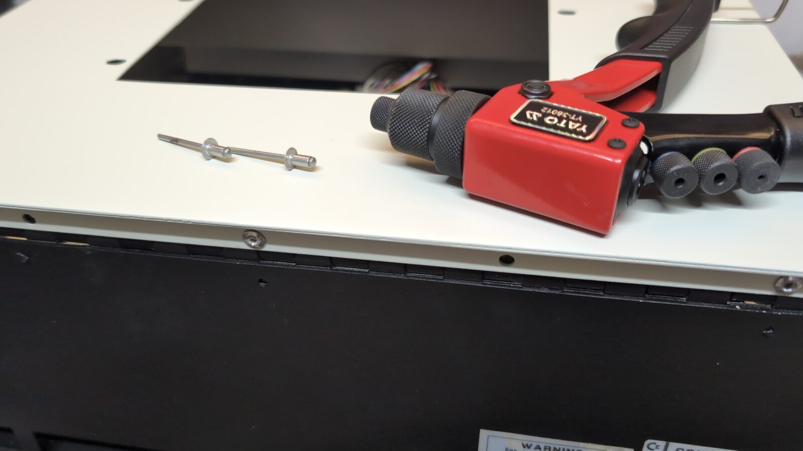
Unfortunately, the case is held together by rivets, and these had to be removed with the help of a drill.
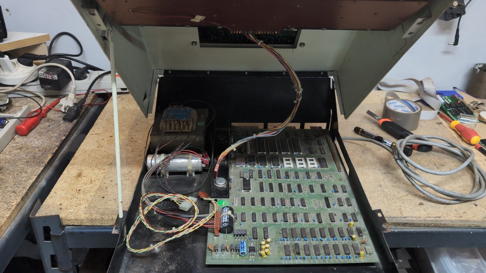
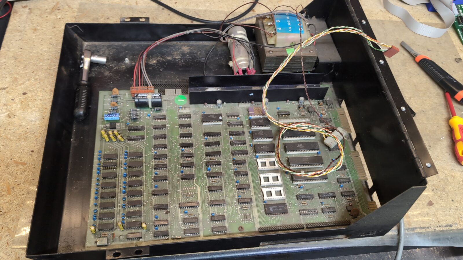
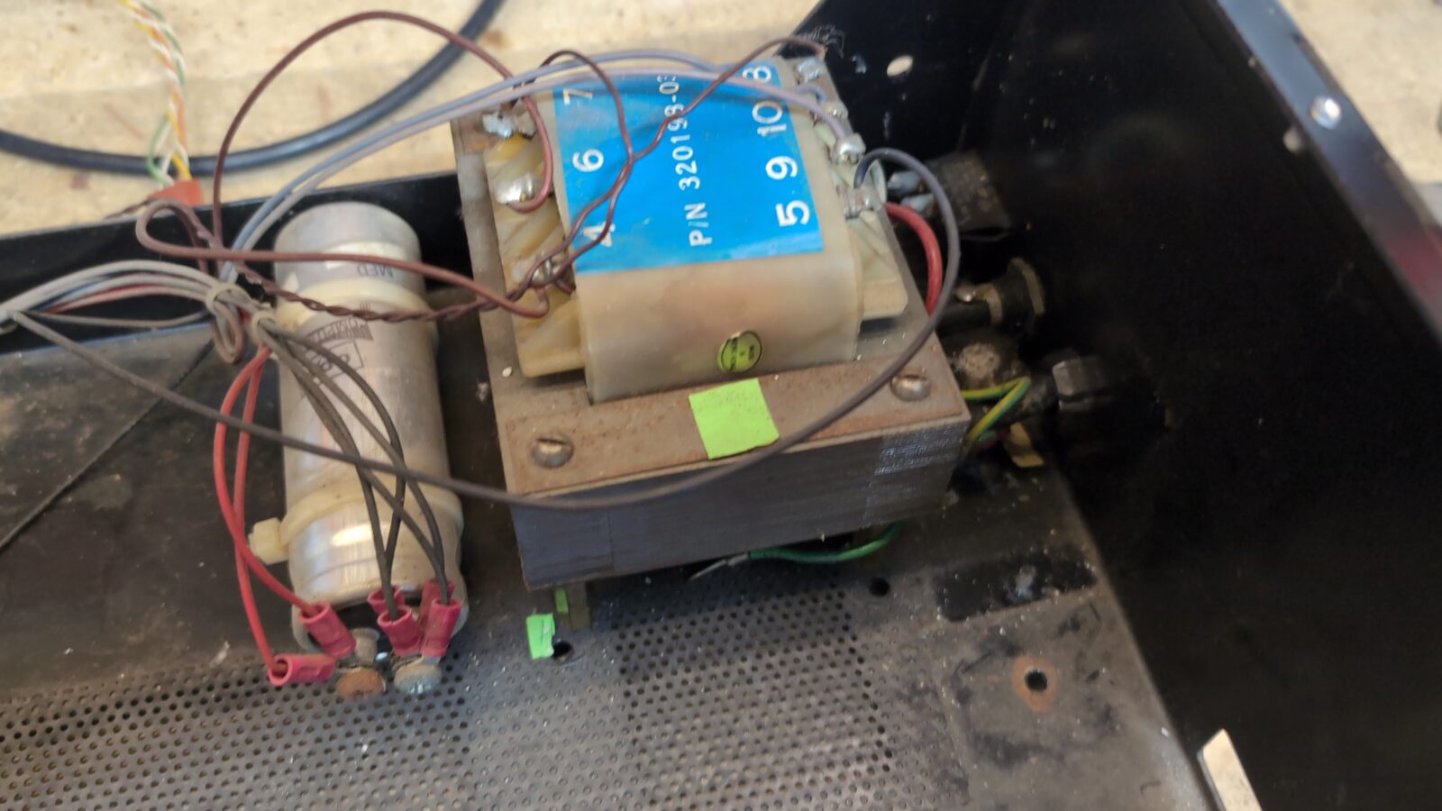
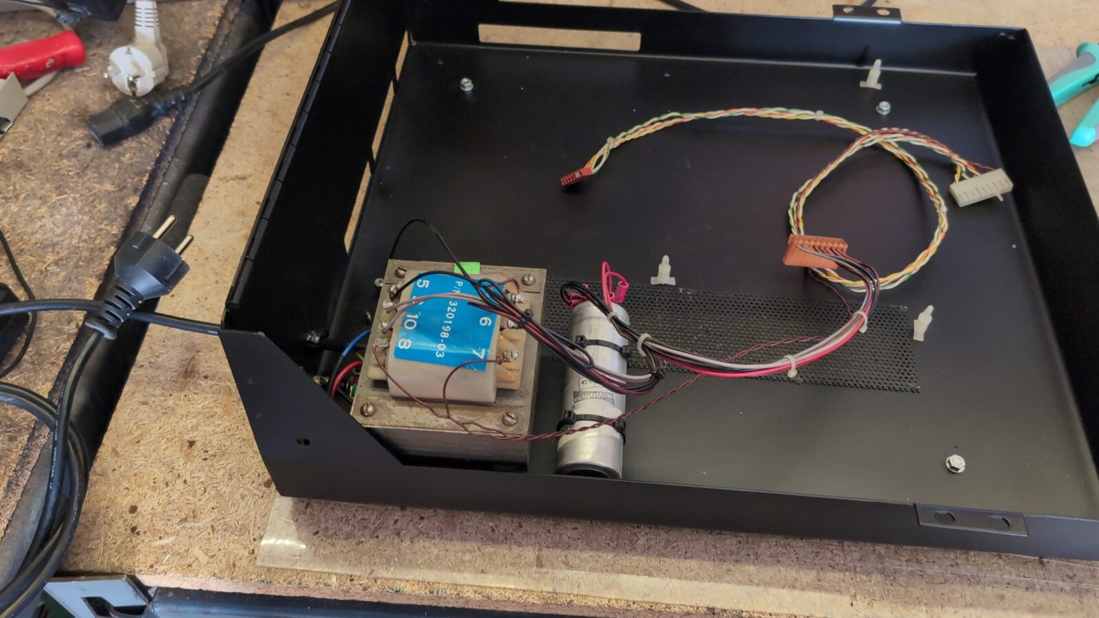
Inside, there is a large transformer that adds lots of weight to the already heavy metal case.
I took some pics again and removed them all. I mean, the rivets :>
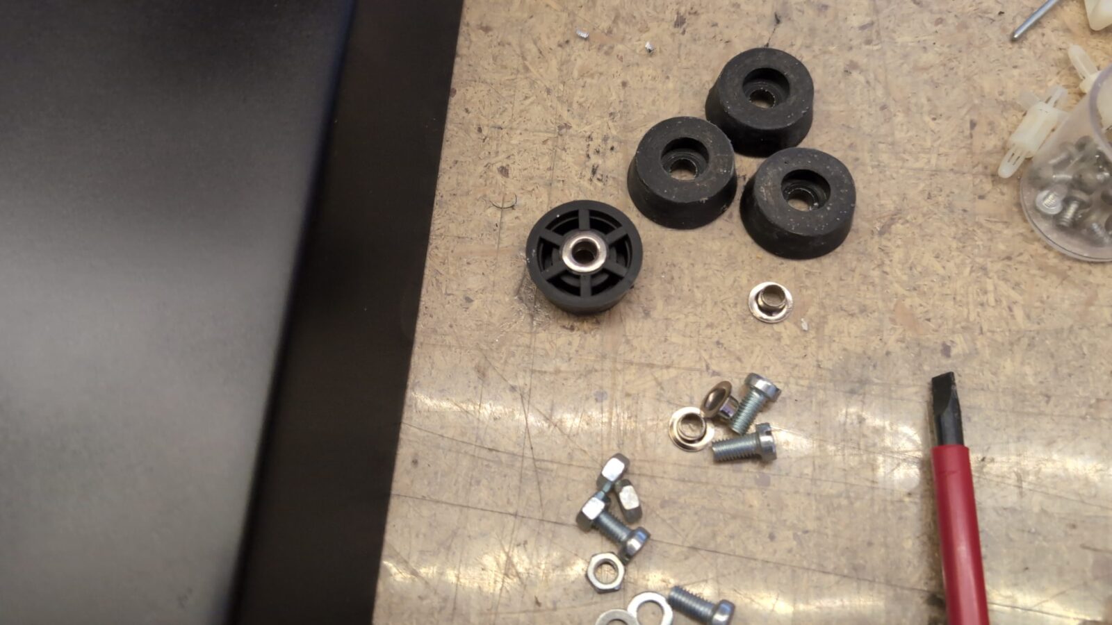
I’ve also removed riveted rubber legs and original stickers.
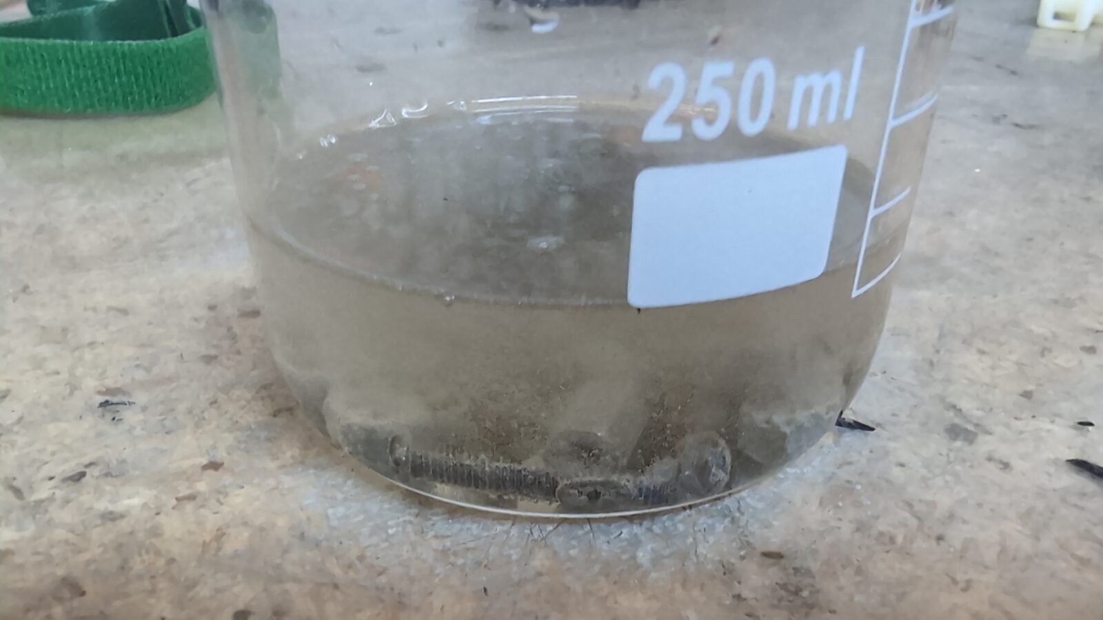
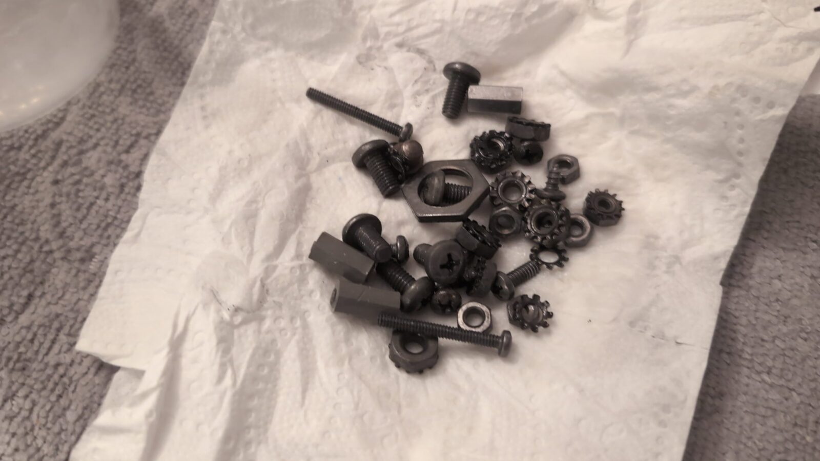
All screws were covered with rust, and this had to be addressed. I usually use a solution of Phosphoric Acid to deal with the rust, and this time it was not an exception 🙂
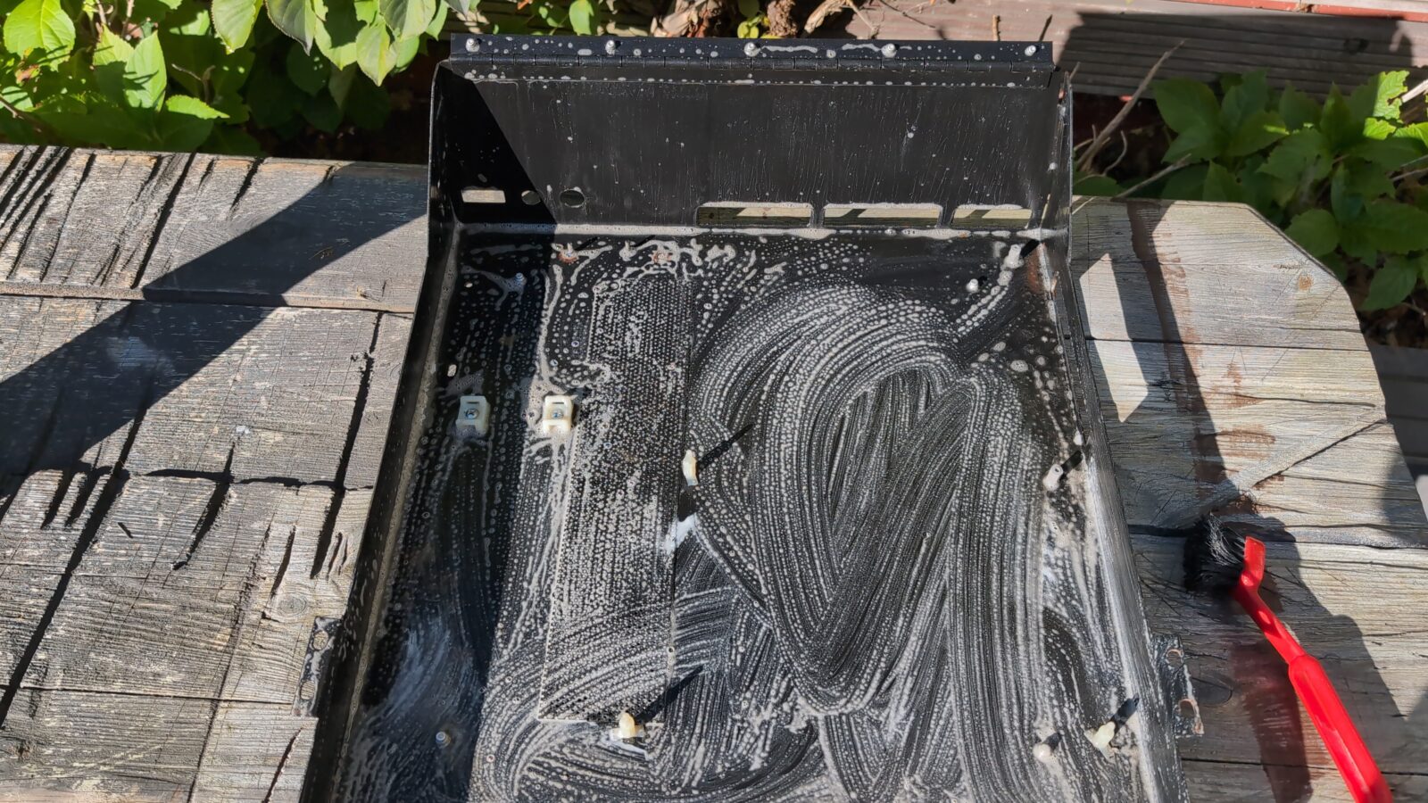
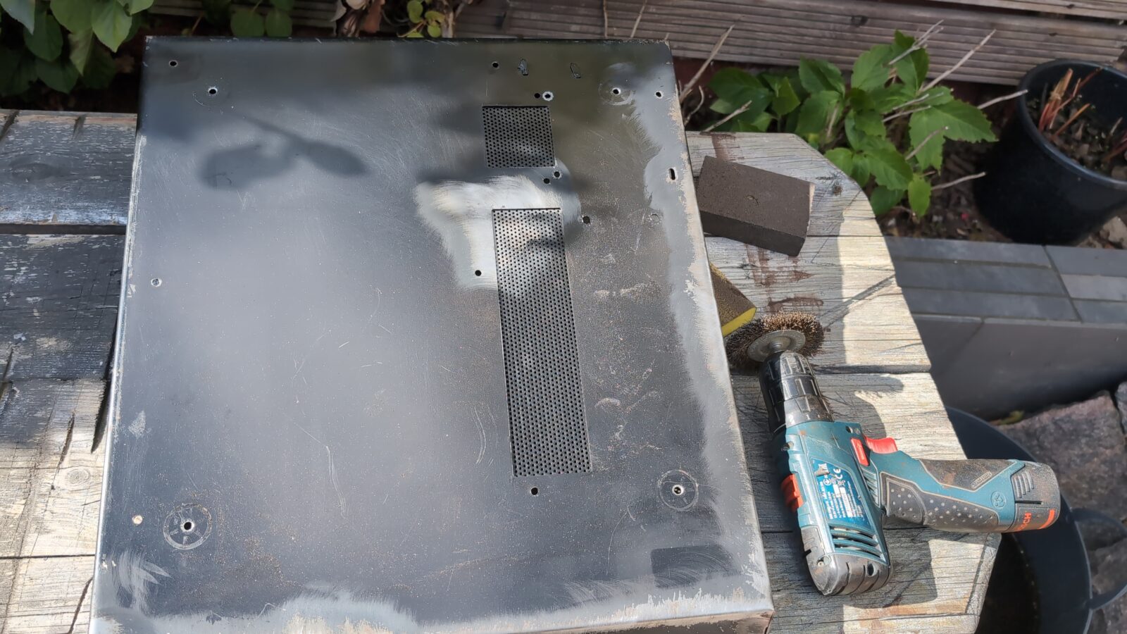
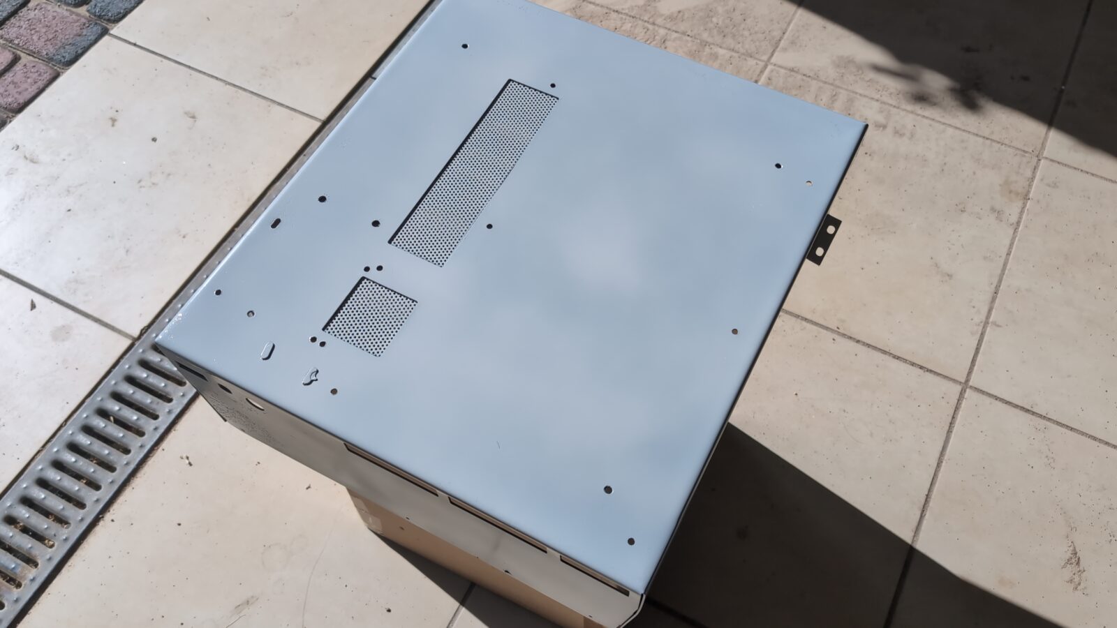
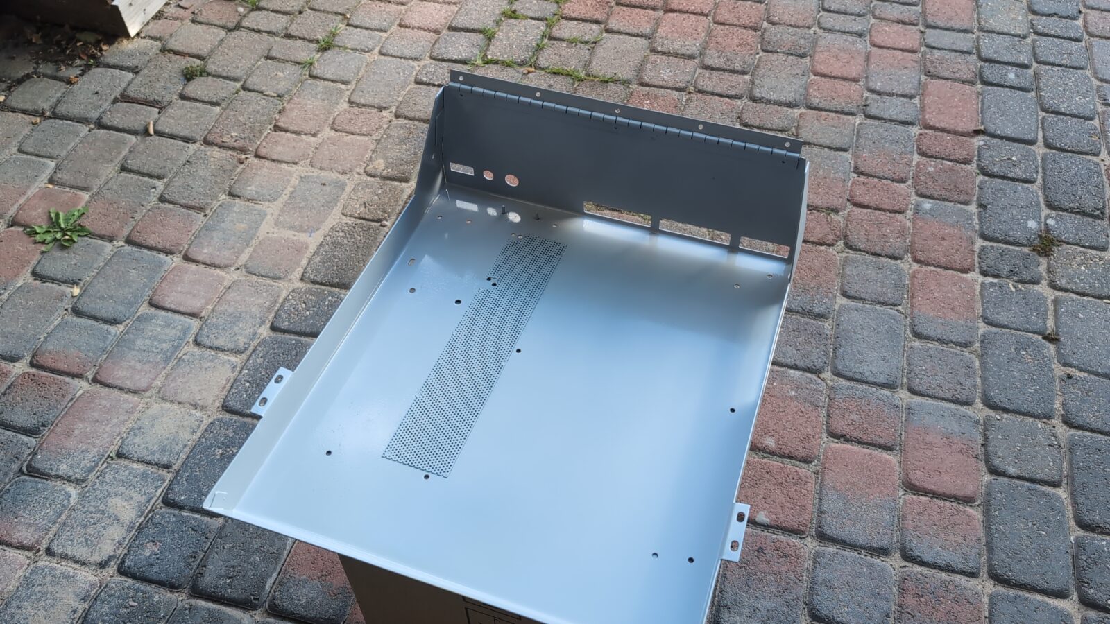
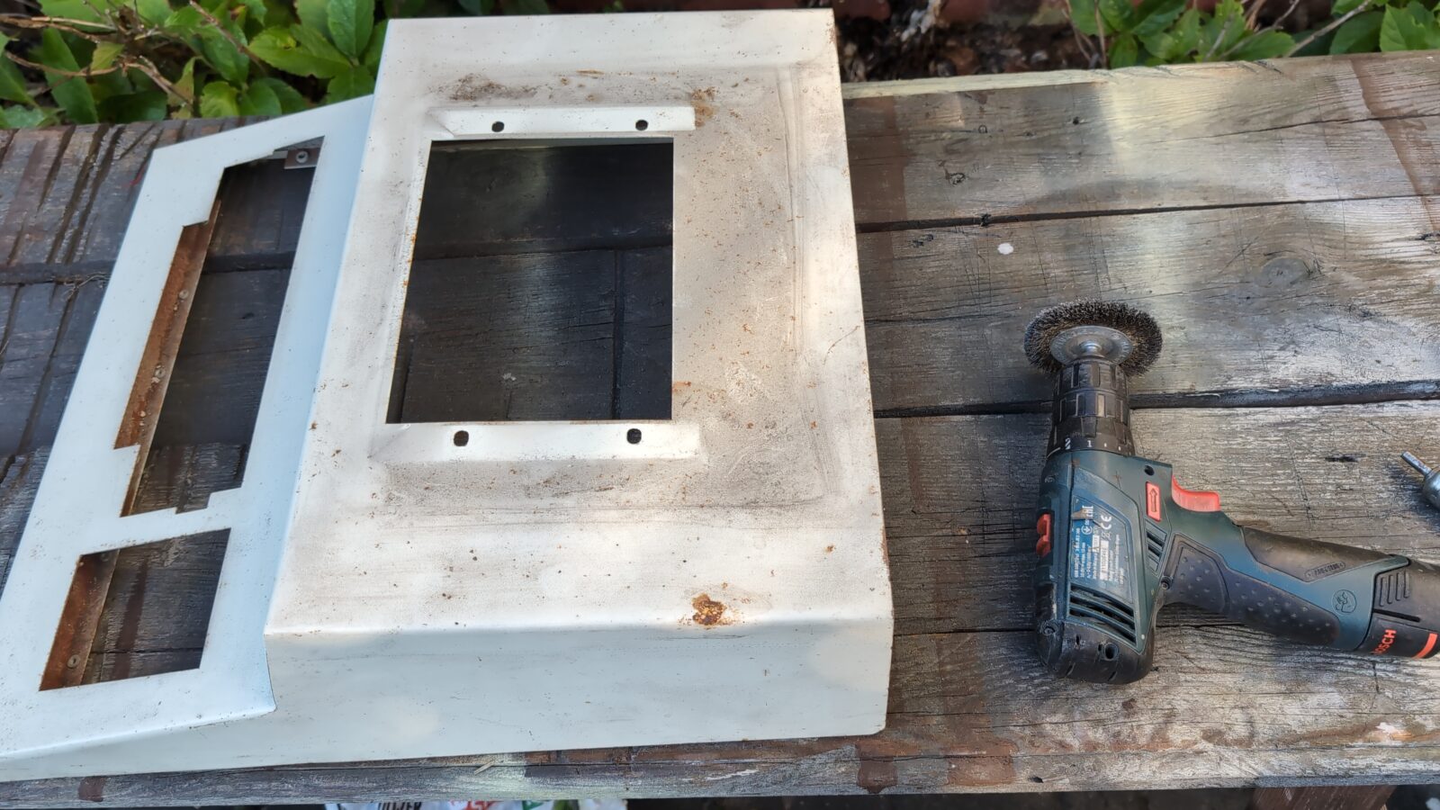
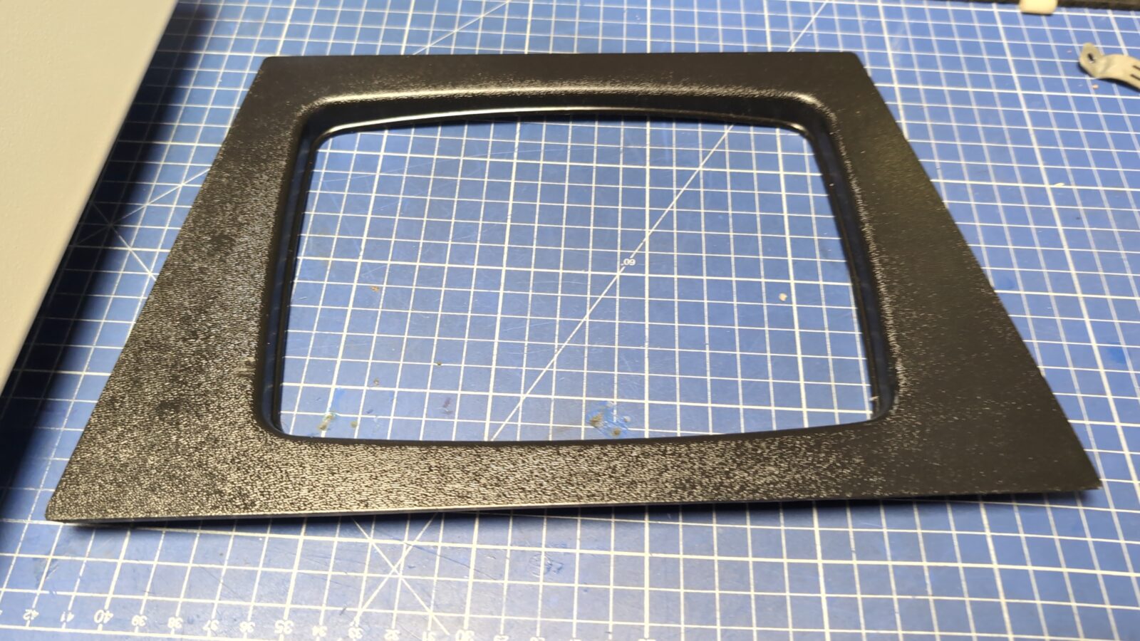
Metal case restoration
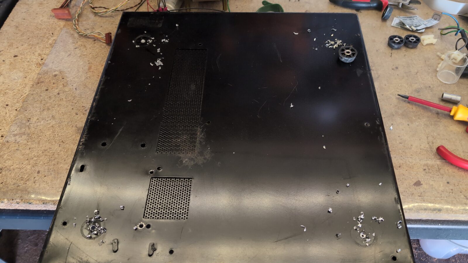
The plan for the case is usual. First, I had to clean it, then remove the rust and sand off the paint layer so the fresh undercoting would stick to it nicely.
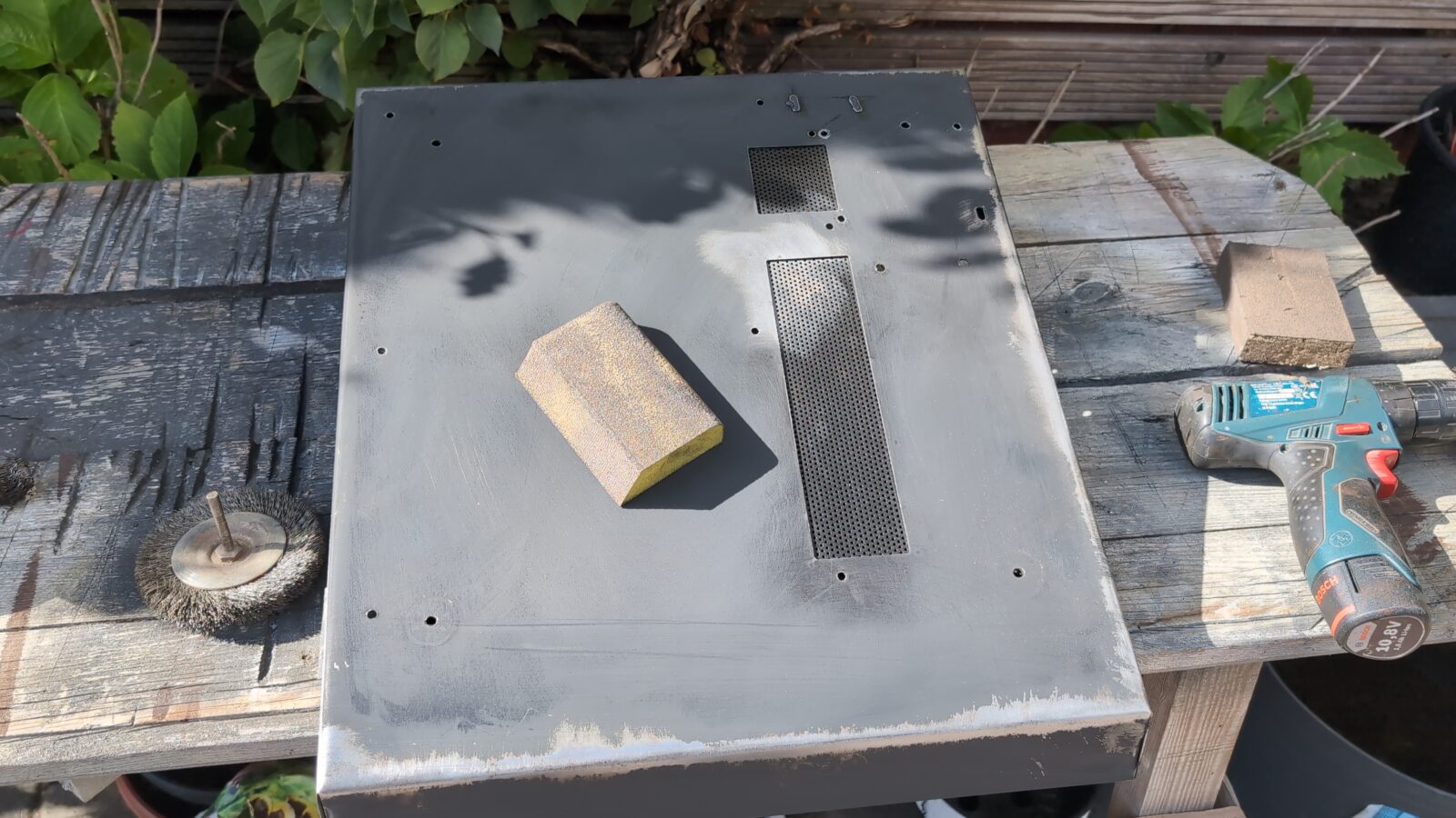
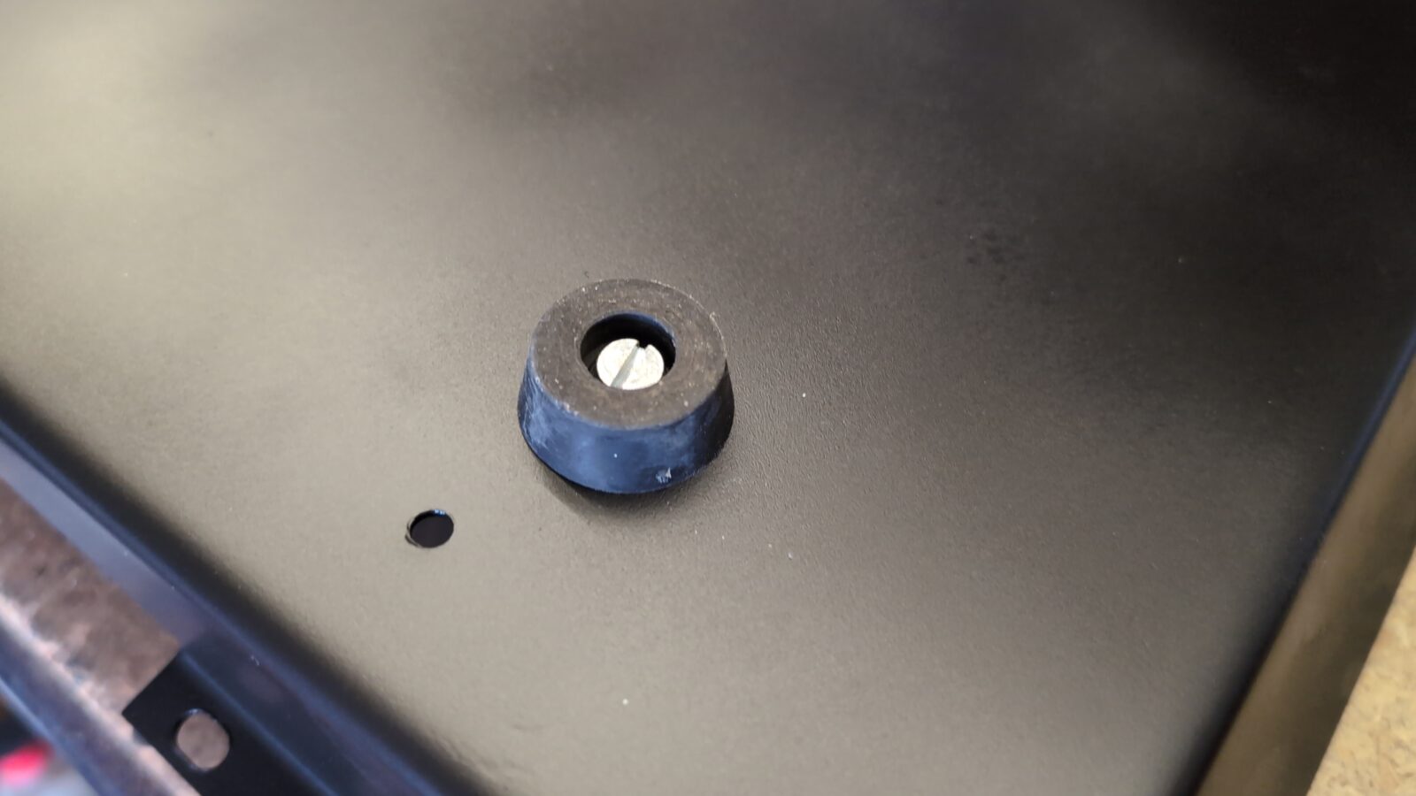
After painting the bottom part in black matt, I’ve screwed on the rubber legs.
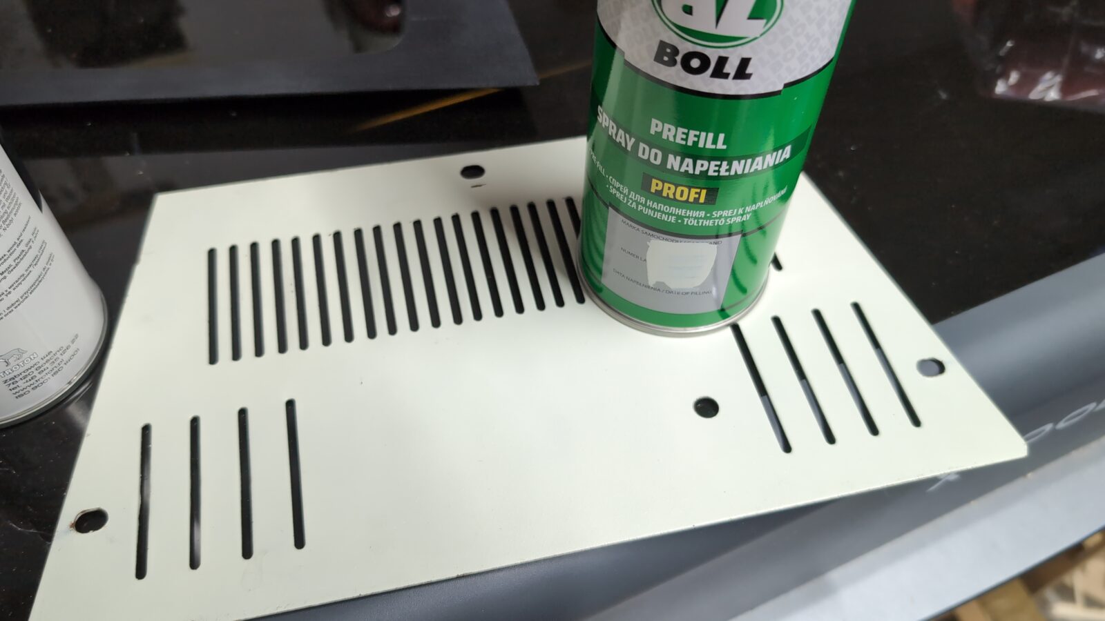
The same procedure was applied to other parts of the metal case. However, for these parts, I had to order a color-matching spray paint as I usually do.
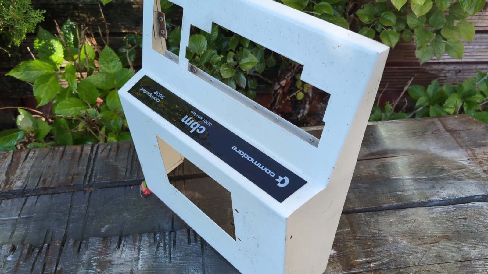
The plastic front panel was cleaned and restored with mineral oil.
With the top part ready, I could clean up the CRT itself and start assembling it all back.
Assembly
There was one last thing to sort out. While doing some tests, it turned out that CRT is still not working. I’ve measured some components and found one more issue. The LM7812 (not 100% sure, but I think it was 7812) voltage regulator was dead and had to be replaced before full assembly.
With the top part ready, I could move on to already painted bottom part of the case.
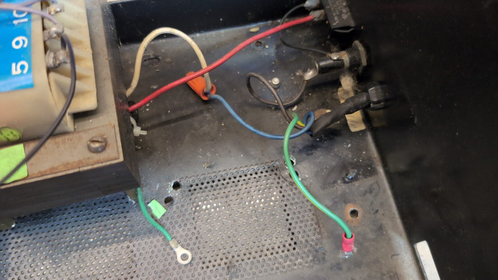
Before putting in the transformer, I replaced the original power cord and fixed the fuse housing, as it turned out, it was broken.
A bit of epoxy solved the problem.
Finally, I could reinstall previously removed rivets that connected both parts of the case.
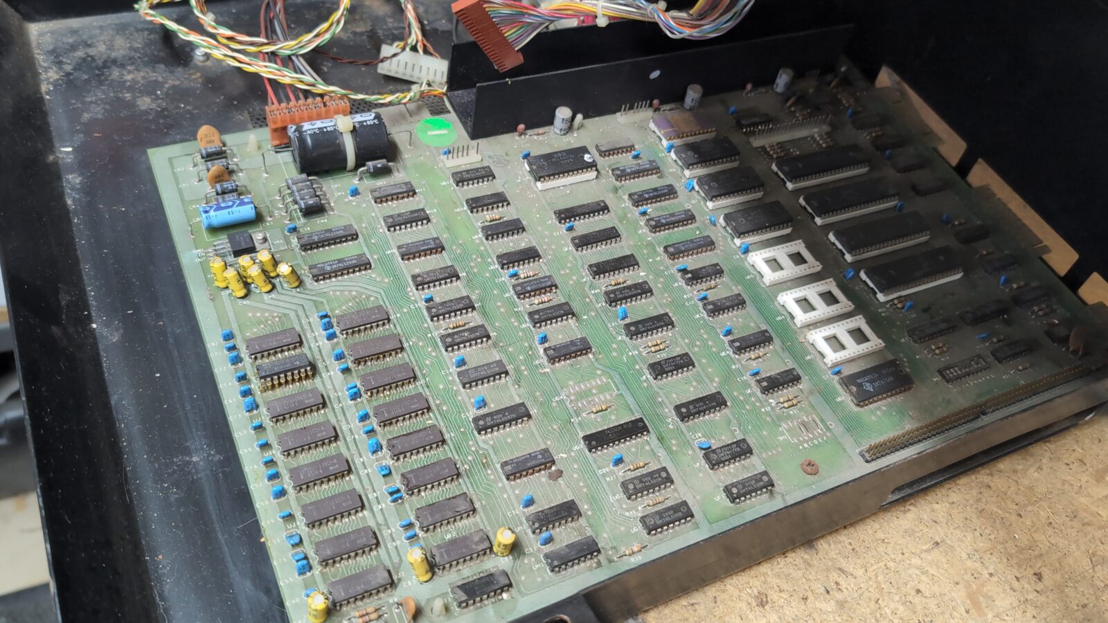
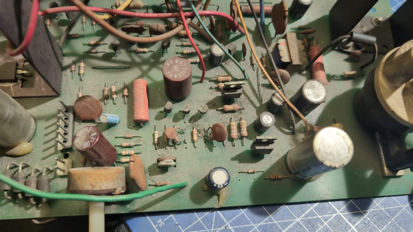
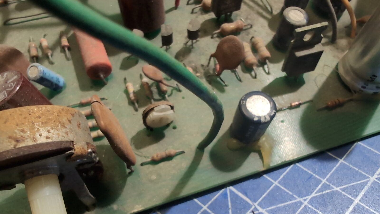
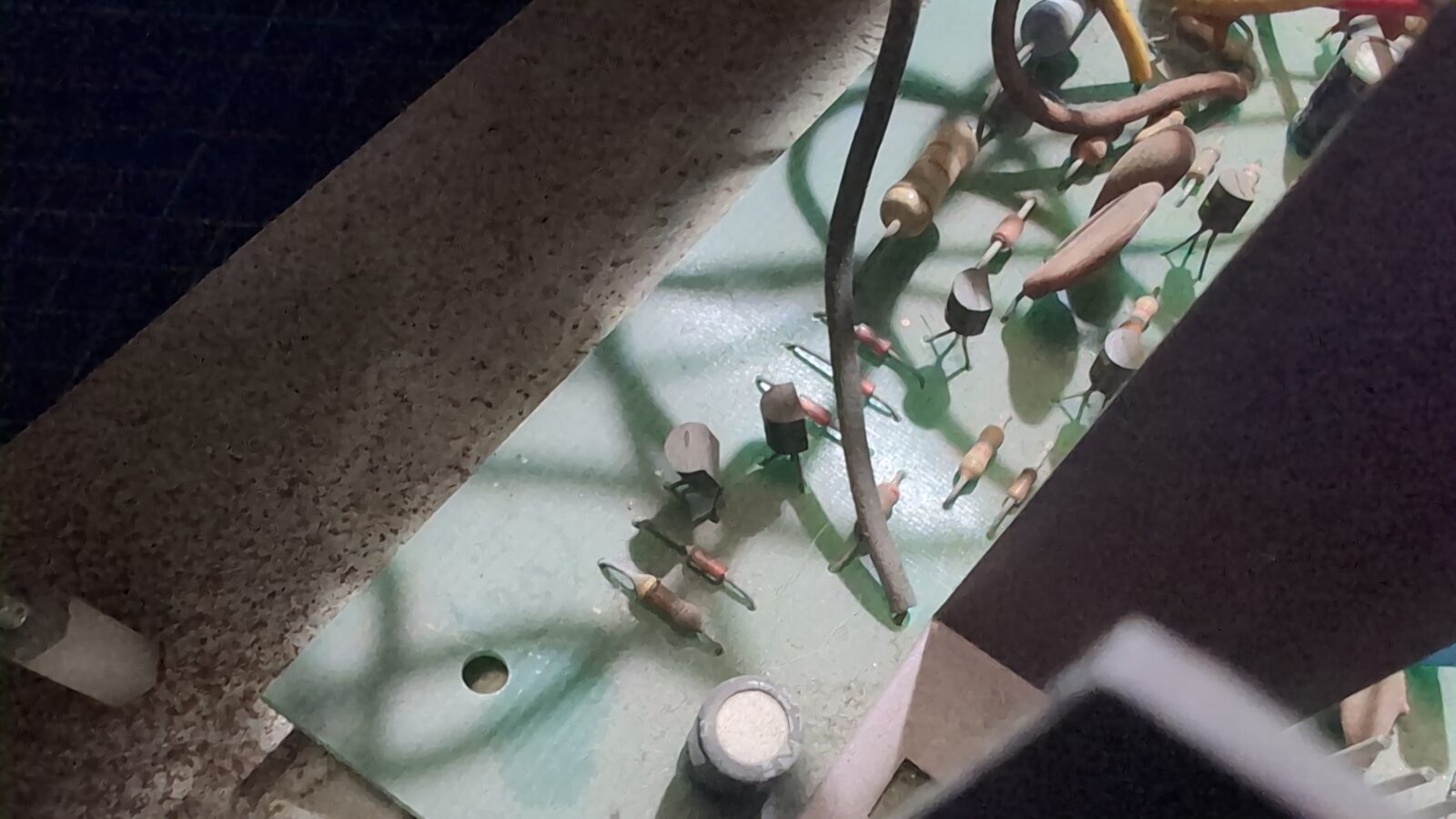
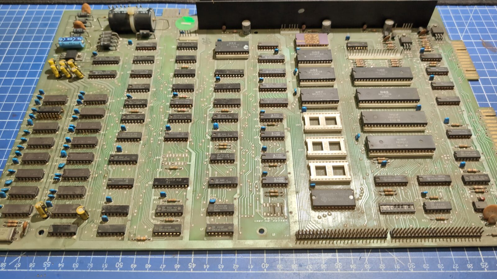
With the case finished, I’ve moved on to the mainboard, which turned out to have a few issues.
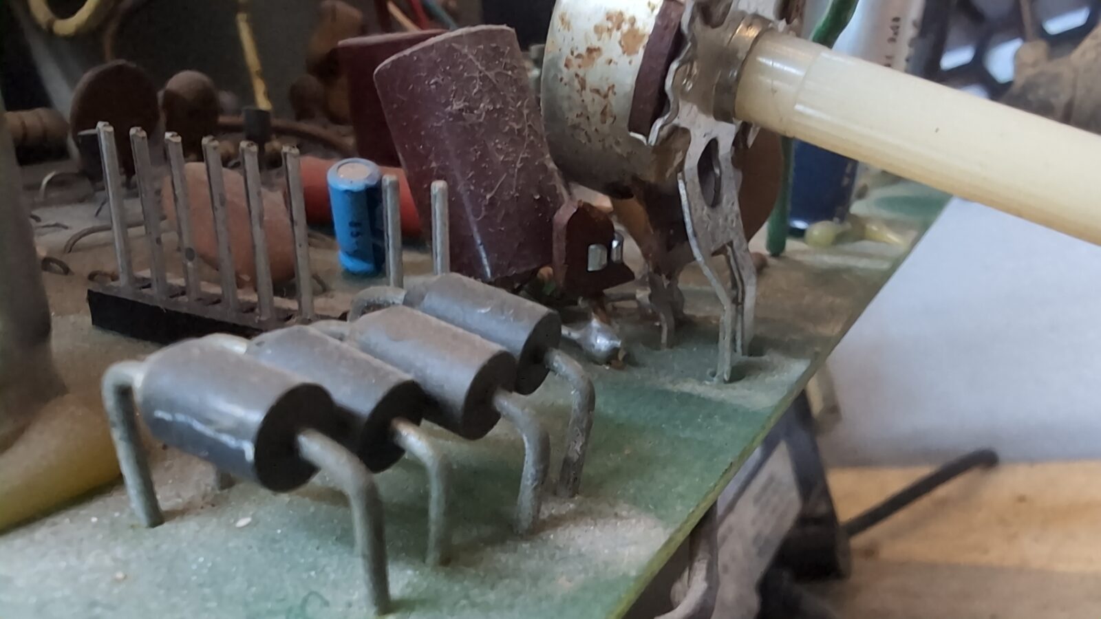
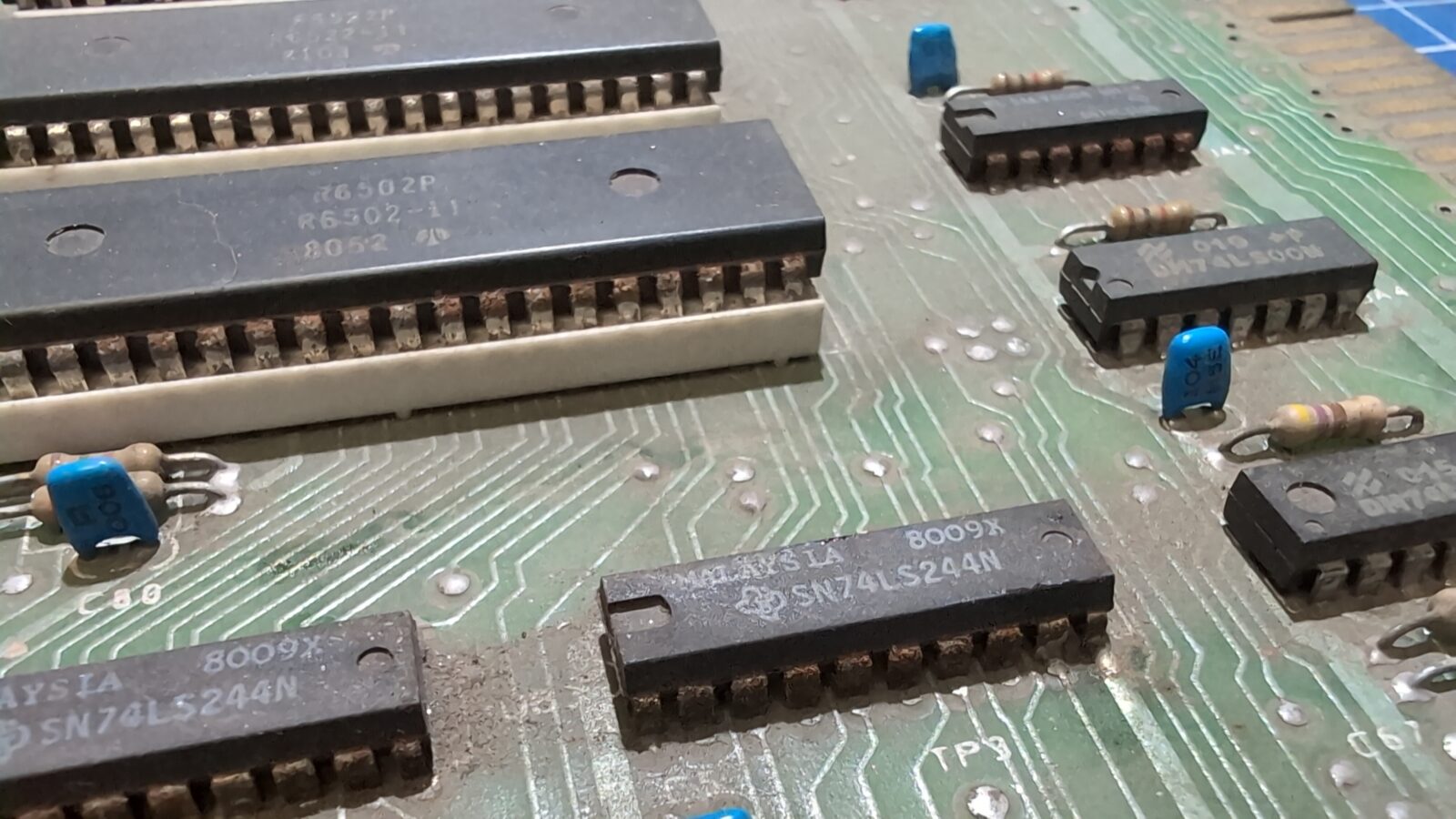
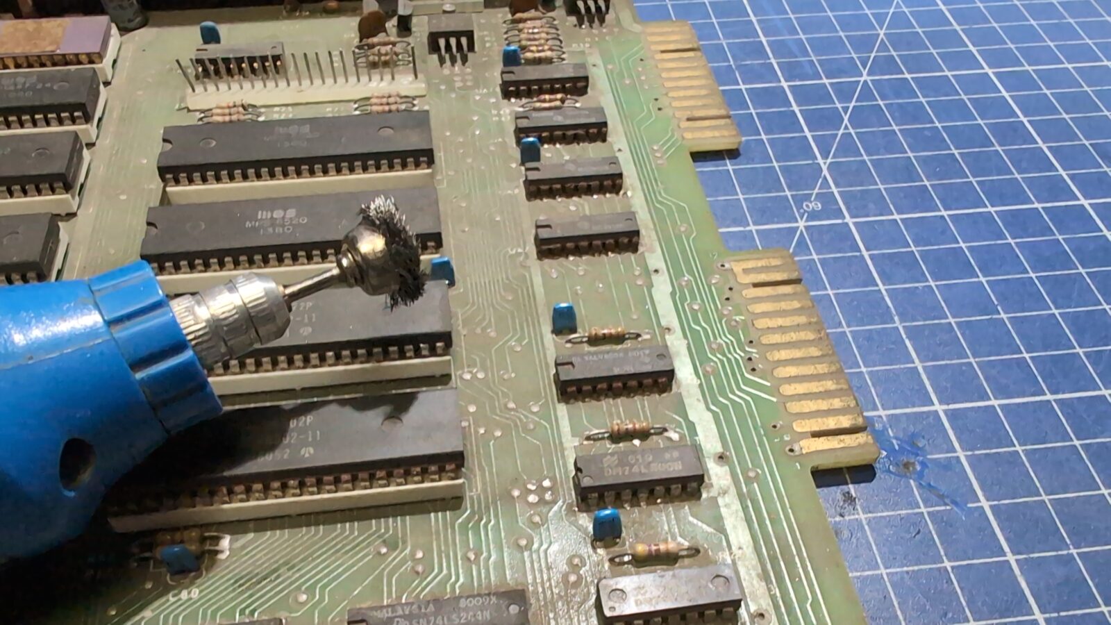
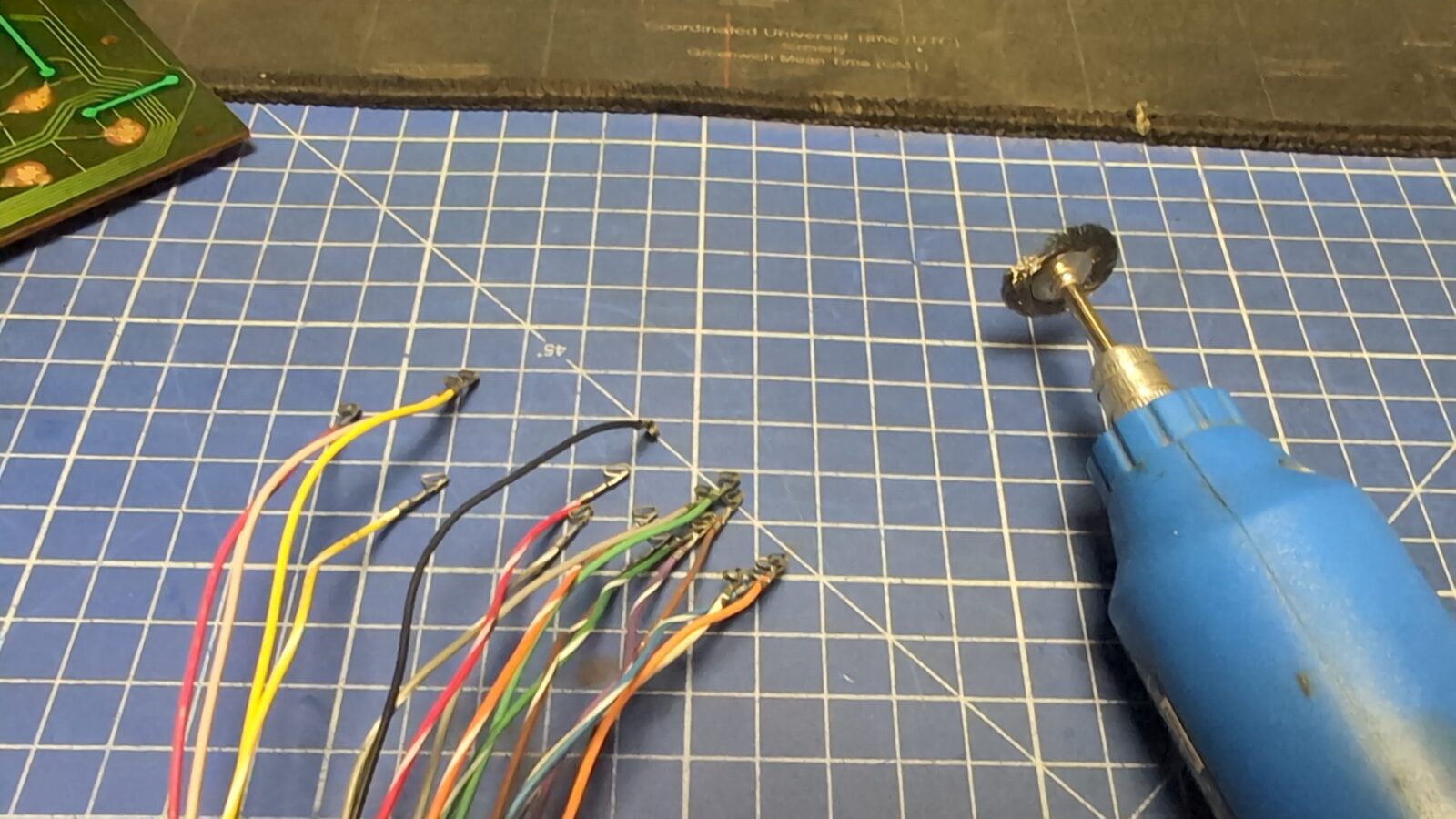
Before putting the mainboard in an ultrasonic cleaner, I first had to clean all the junk that built up on the ICs. Mostly, partially corroded silver plating on IC’s legs. I’ve used a small rotary tool to clean it.
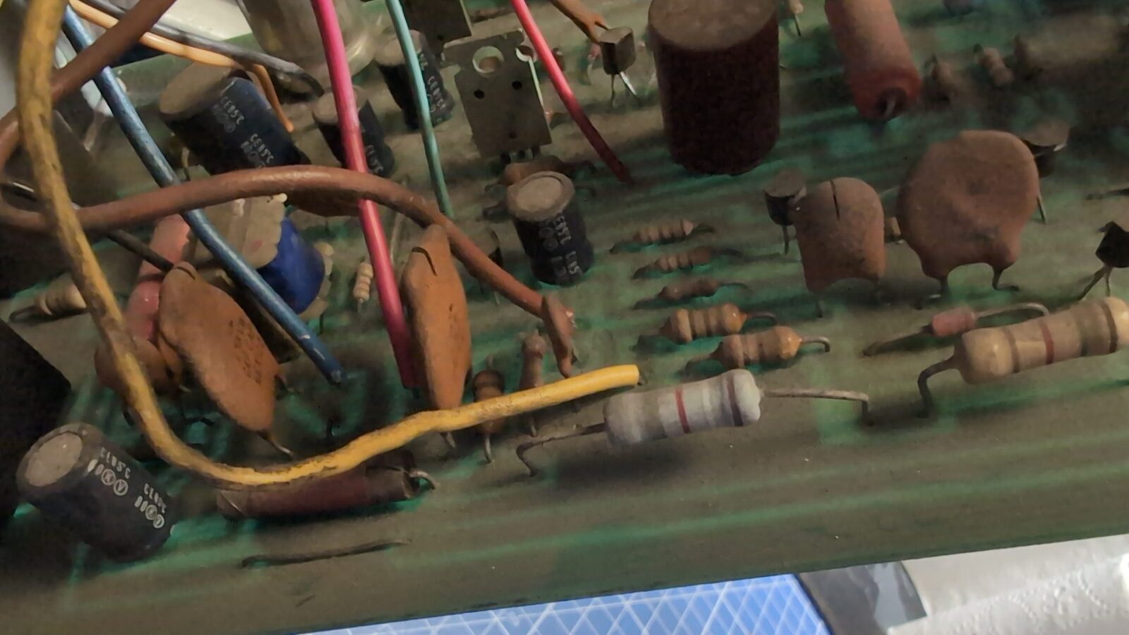
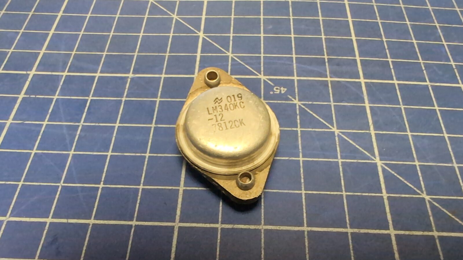
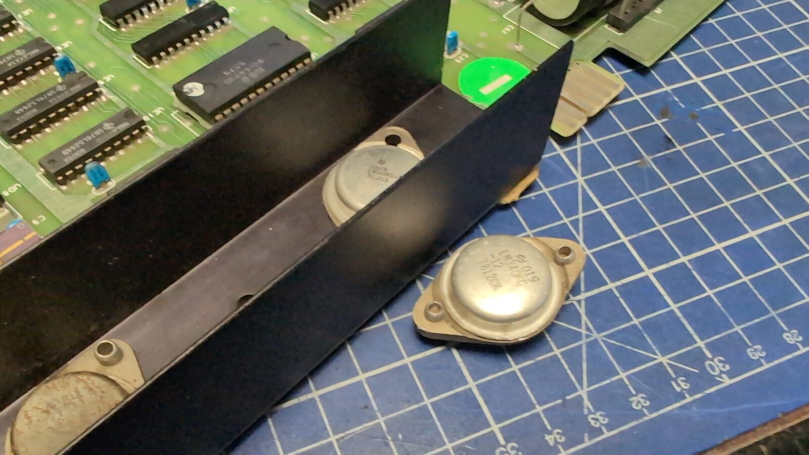
The machine didn’t work after powering it up, so I had to run some tests with a multimeter, and it quickly turned out that another voltage regulator is dead. This time it was LM340KC. I’ve ordered a fresh one and replaced it.
Now, the quick on-bench test proved that the machine actually works, YAY! … kinda … because it only booted once in three tries.
I’ve decided to replace some old IC sockets, and that sorted out most of the problems. Still not all of them, as this time it booted, but the video signal kept on disappearing sometimes. Further searching showed that the onboard video pin header is oxidized/tarnished, as well as the pins in the plug itself. A bit of cleaning sorted the issue.
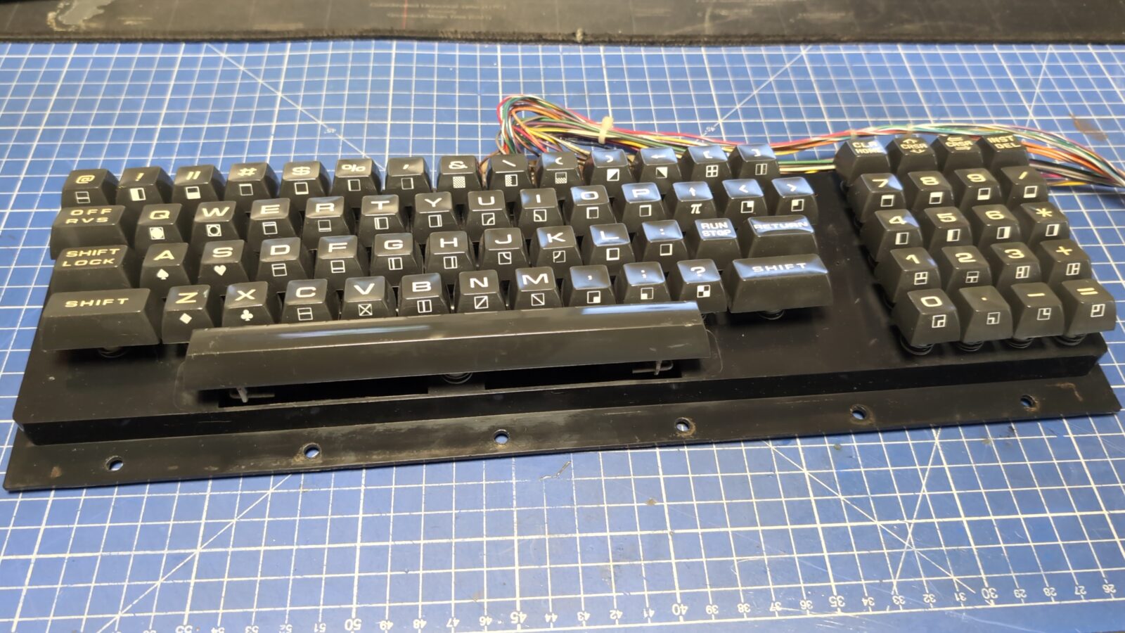
Keyboard
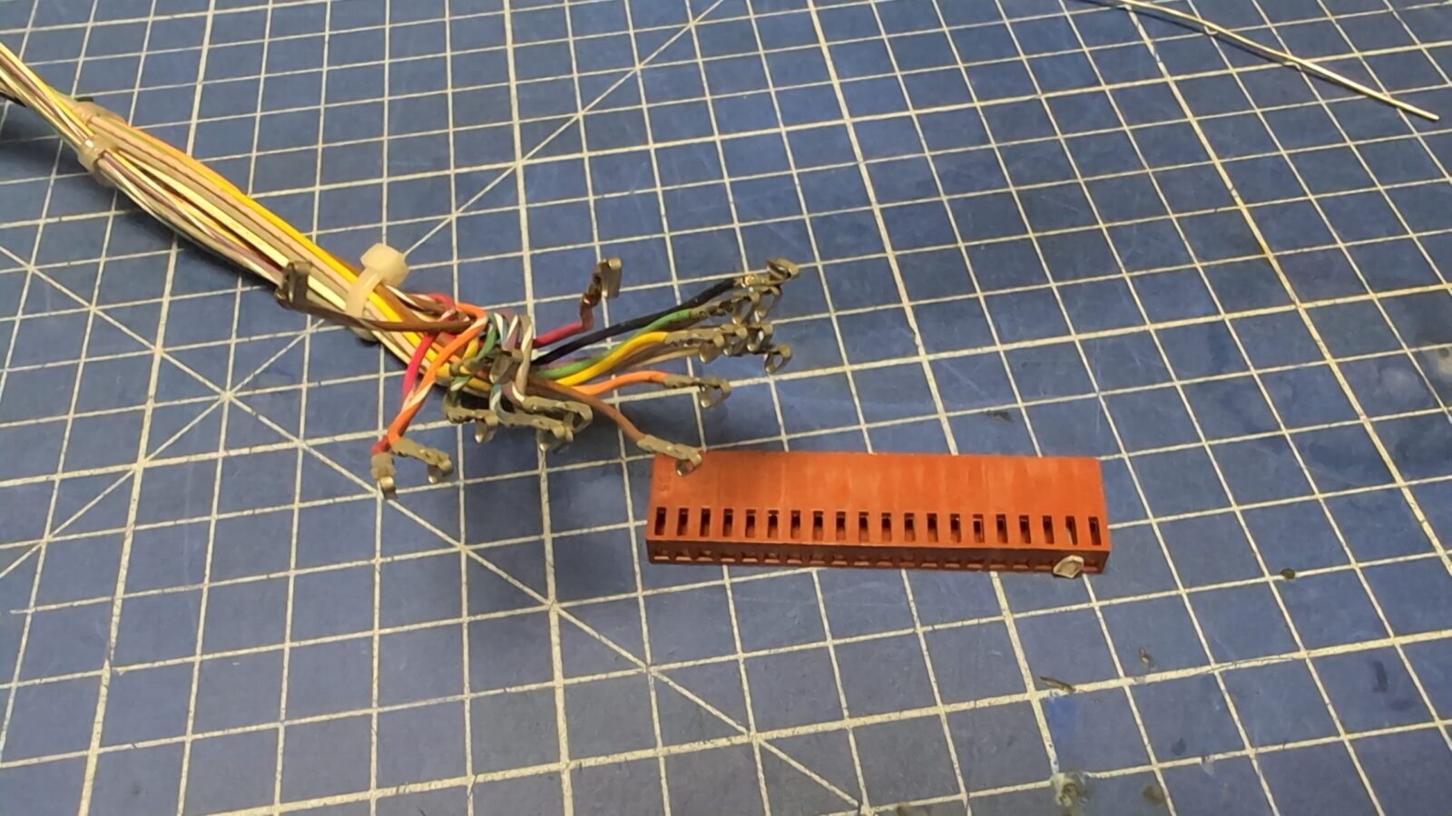
The last piece that had to be addressed was the keyboard. It only partially worked, so I started with the pin header and the connector cleaning first.
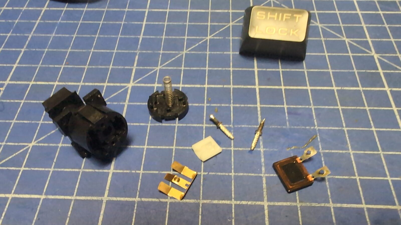
That didn’t help much, so I’ve disassembled the keyboard and cleaned it thoroughly. Also, SHIFT-LOCK needed a bit more attention as it is built differently from other switches.
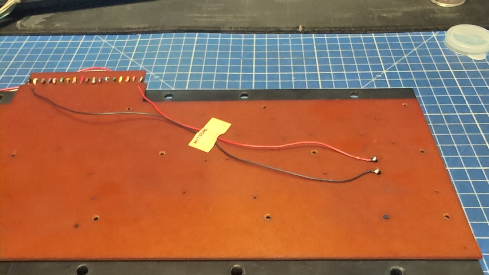
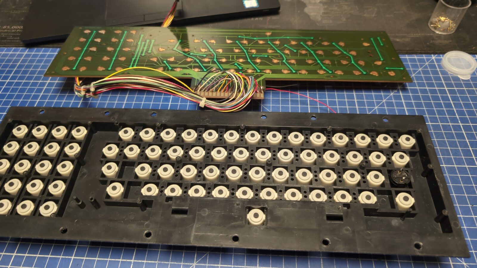
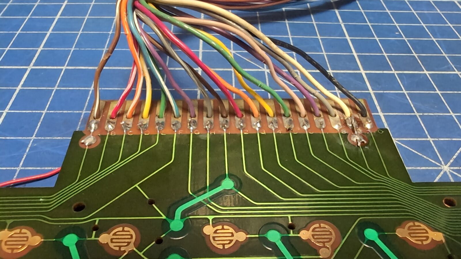
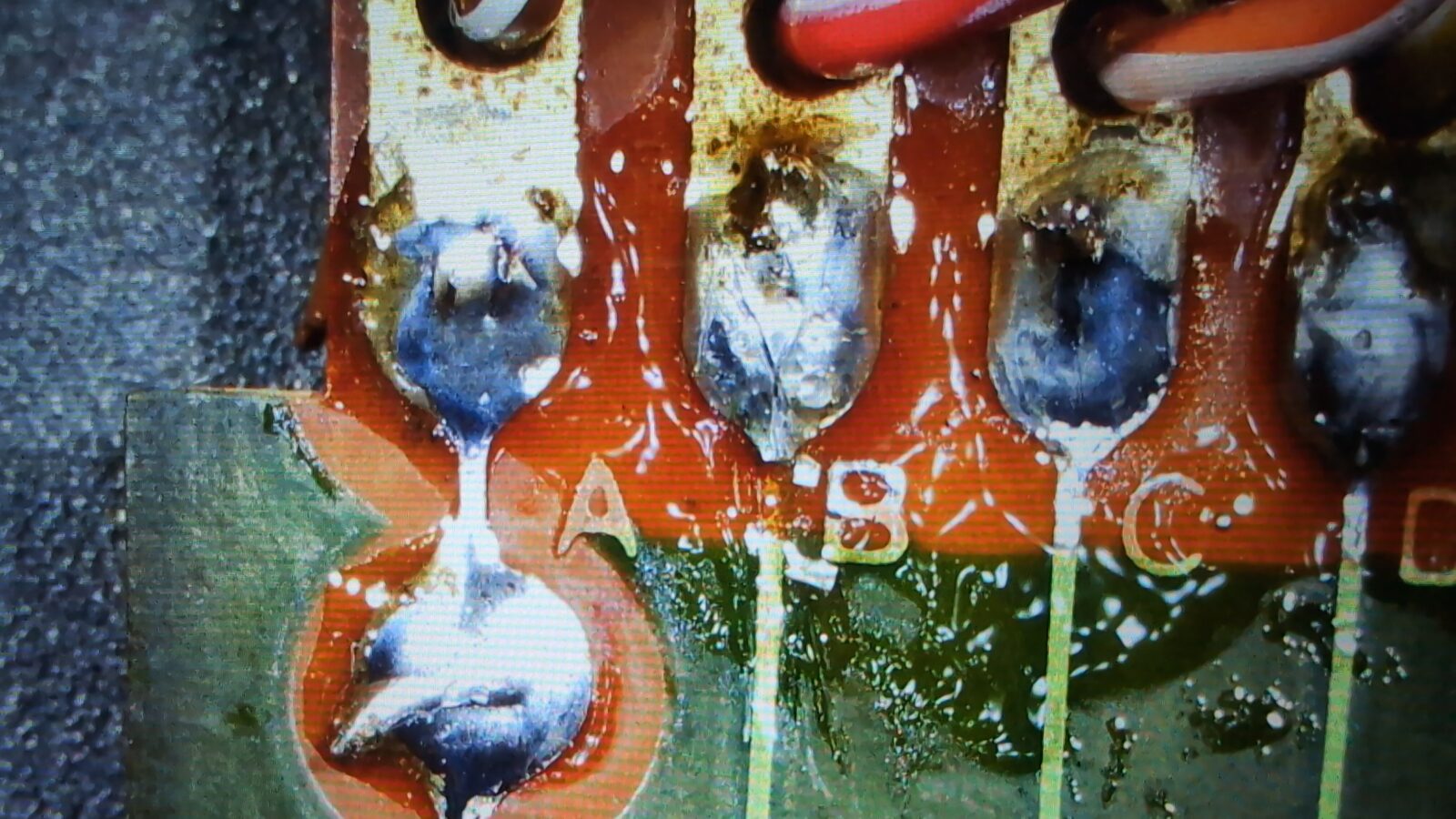
After reassembly, the keyboard mostly worked, but one of the columns was completely dead. This is often a sign of a broken trace/wire of the whole section. Indeed it was, but it took me a decent while to figure that out, and it would not be that easy if I didn’t have a micro camera with an LCD. The break was just next to letter B on a PCB, and it looked normal until touched with pliers.
I’ve fixed that, and KB started to work as expected. Well, kinda, because when the machine came back to Zoltar, it turned out that the “C” key sometimes doesn’t work correctly. I guess the rubber pad has to be cleaned a bit better.
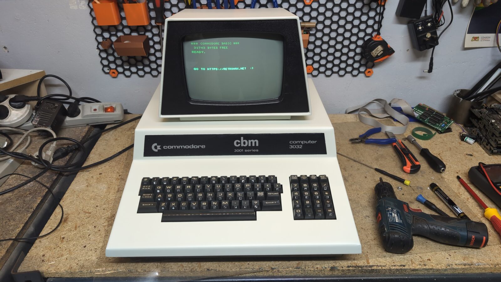
Final pics
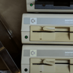
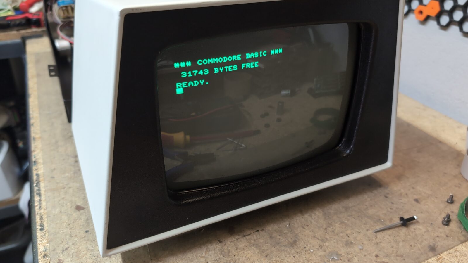
Finally, I could take some pictures of a working machine. Tadaaa! My first PET was restored 😀
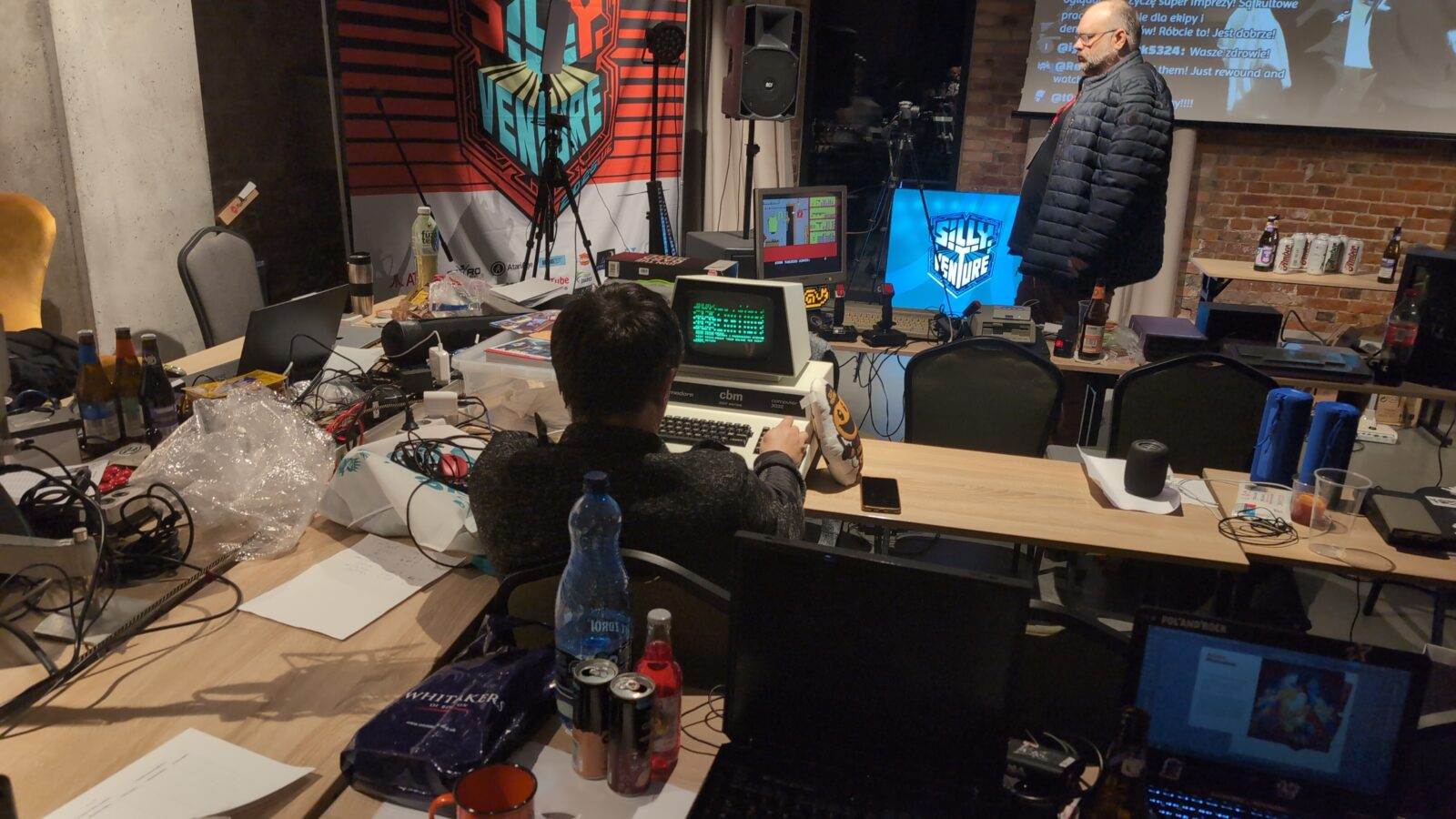
Final pic is straight from the SillyVenture party, where Zoltar X and I met, so I could give him his machine back 😀
Zoltar wouldn’t be himself if he didn’t code something on it right away :>
Outro
—< !!! SOLO/NG pretty please don’t send me fucks in the scroll for … you know what 😀 !!! >—
Now we can safely watch some cool PET demos!