… or why u not work !?
< The story >
Soooo, this is a story about a little boy who was never born
< /End of story 😀 >
Mmmmkay, poor joke ;P
The real story is that I had an occasion to get a Grey ZX Spectrum 128k +2.
Obviously from the bidding portal and obviously I wasn’t sure if it is in a working state. But hey! If I knew that, it wouldn’t be a challenge riiite?
After nearly two weeks I became a happy owner of +2 Grey in an unknown state.
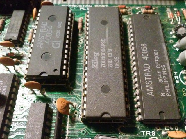
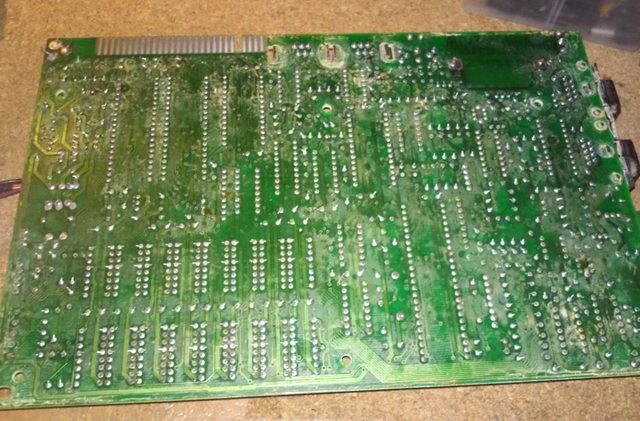
Several C64 repairs later, I’ve finally had some time to have a look at this unit, and here is how it looked:
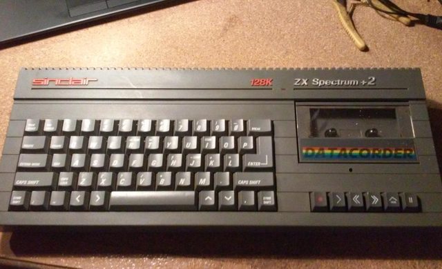
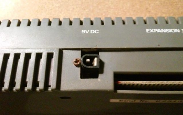
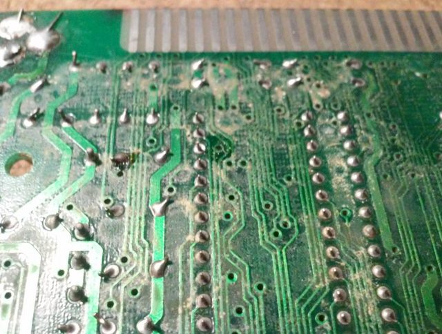
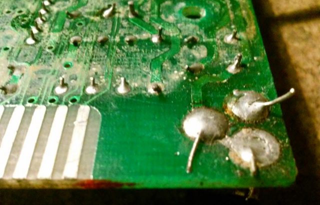
Here are a few shots of PCB before I’ve put my hands on it (nice and dirty) 🙂
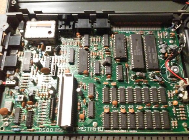
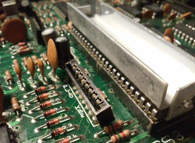
Cleaning
Aaaawwrite fixes time.
First things first, which in this case is cleaning.
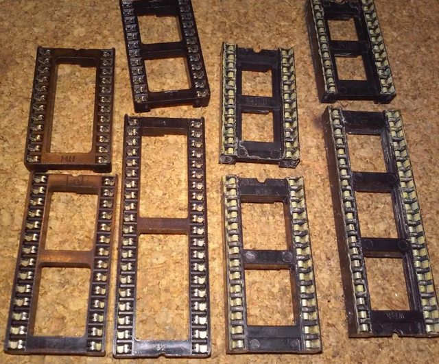
I usually remove chips from their respective sockets before cleaning … and surely I did it this time too … however, I had to remove all sockets instead of chips only. Here is why …
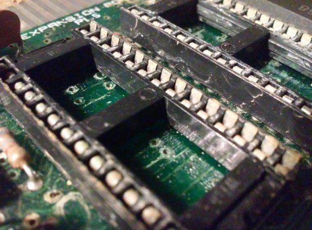
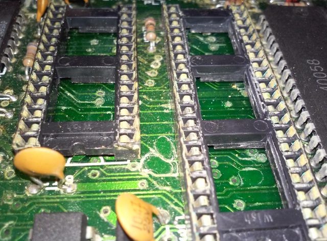
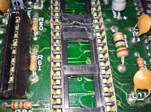
Just for a comparison, new sockets on the left 😉
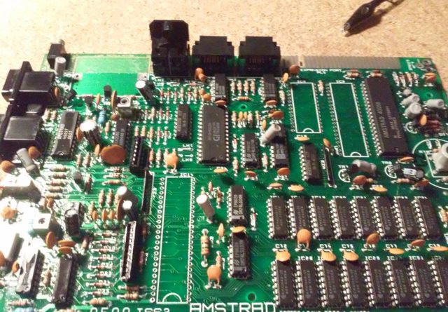
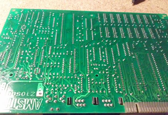
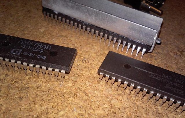
PCB cleaned and ready to solder sockets. I’ve also cleaned chip pins with a small, metal rotary brush.
Transistor mess
At this moment I wanted to test if everything works fine after cleaning.
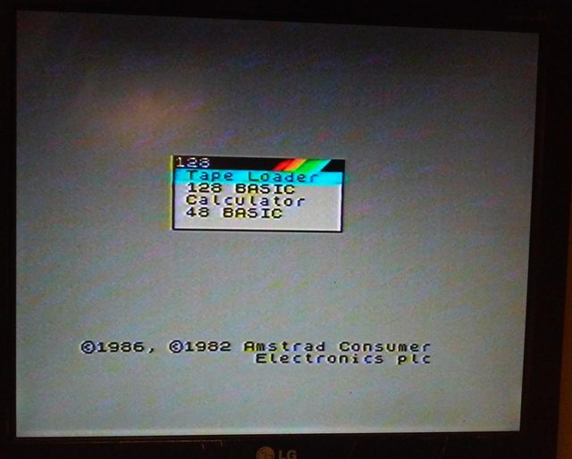
I’ve connected speccy via RF modulator and I was greeted with a boot screen YAY!
The next step was to get a video signal through monitor output.
I was assuming that the video output quality will be much better.
How wrong I was…
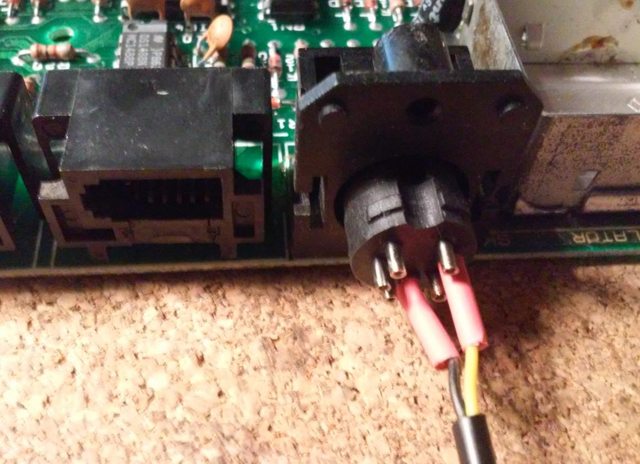
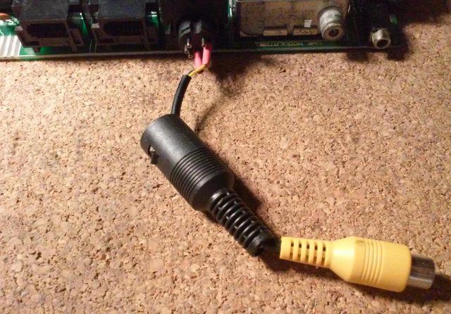
The only output I’ve got was a distorted mess on the screen.
I’ve started digging a bit and found out that there are quite a few manufacturing mistakes. That surprised me a bit but let’s get to the details.
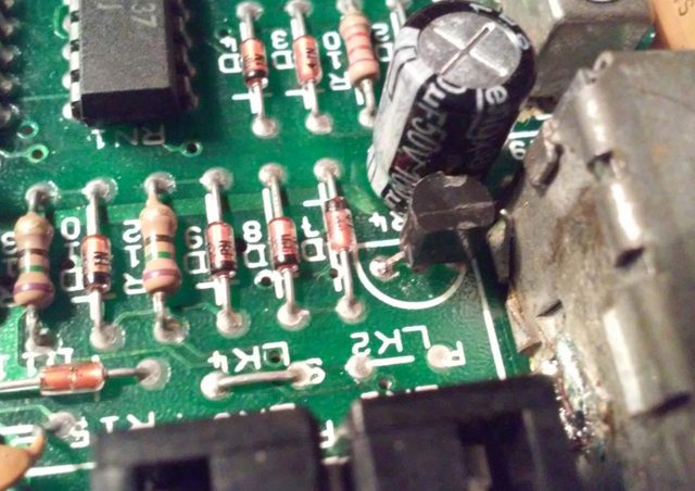
It turned out that on rev.3 mainboards, very often transistors are soldered on in the wrong way (emitter and collector swapped).
Looks like guys in Amstrad had a lot of transistor suppliers and got kinda lost in it 😀
In my case, transistors TR4, TR5, TR7, and TR8 had to be resoldered.
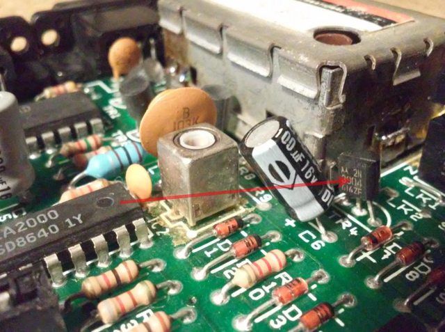
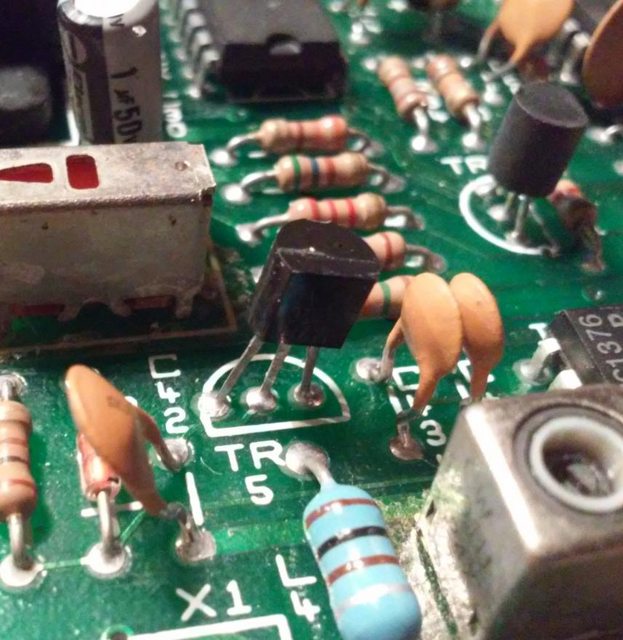
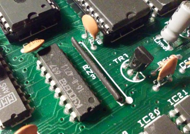
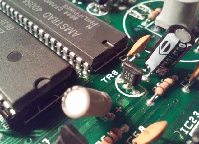
Here is an example of a properly resoldered TR4.
Video
After this operation composite signal started to work again but to my surprise(again), it wasn’t much better than a blurry RF that I’ve already tested. According to smart guys from internetz this poor quality of the composite output is caused by at least three factors.
The first is an old inductor (L2) circuit, the second is audio interfering with the composite signal, and the third (ghosting) is a lack of a new LC filter near the TEA2000 encoder.
An old inductor circuit can be easily turned off by simply removing a ceramic capacitor C3.
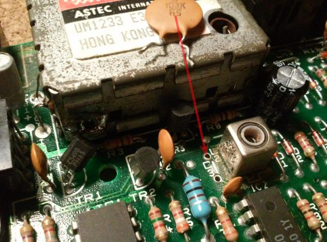
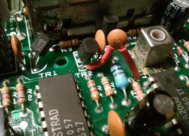
The second problem was also easy to solve. It can be done by redirecting another nearby ceramic capacitor(C31 if I remember correctly) straight to one of the TR2 transistor legs.
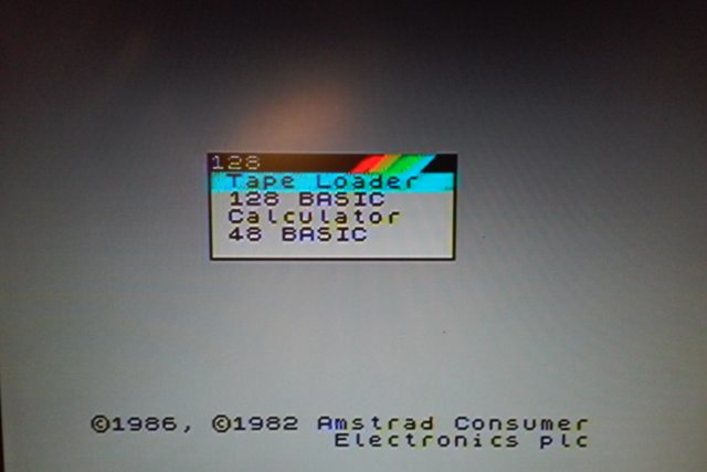
I skipped creating a new LC circuit simply because I didn’t have a 15mH inductor on a shelf. However, after these two simple mods, the screen started to look way better. Keep in mind that it still can be improved.
Final cleaning
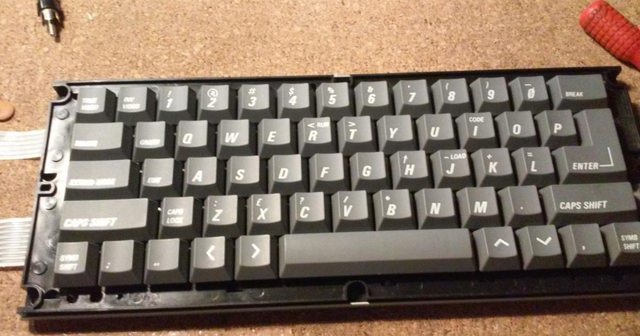
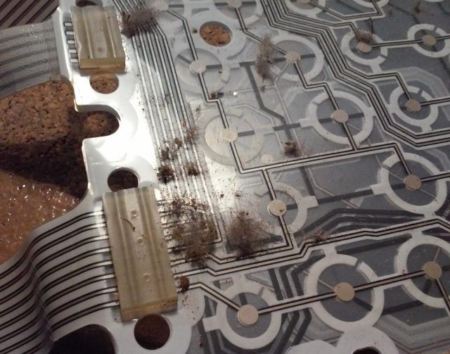
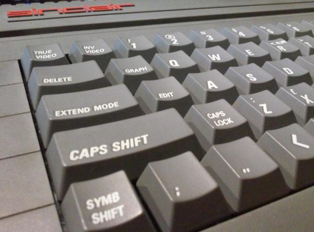
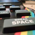
The keyboard was in very good shape but a bit “buggy” lol
Simple cleaning did the job.
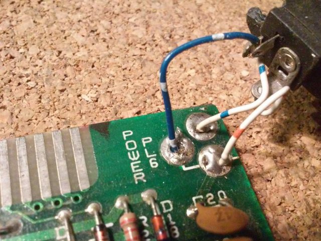
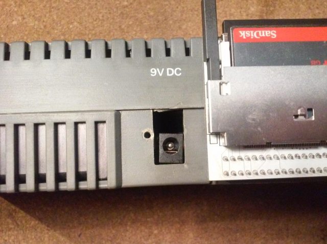
I’ve also soldered on a proper power socket.
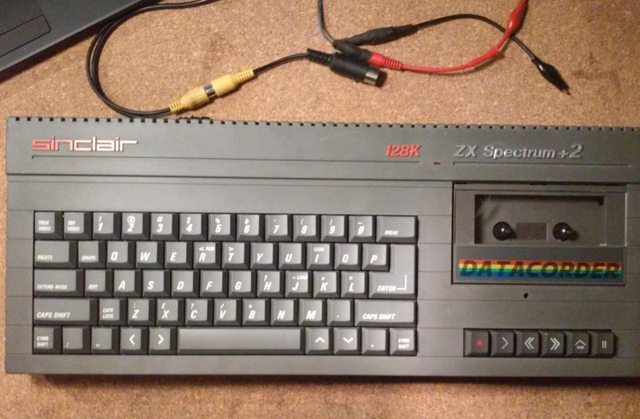
Aaaand that’s it. After a few hours of work, I’ve got a beautiful Grey ZX Spectrum 128k +2
Here is how it works with Lothareks Divide2k14
ZX Spectrum 128k +2 – GREY from pit on Vimeo.
OUTRO
If you want to get retro gear or hardware modules, please visit our shop
New products are being added every month.
Also, please support our work by spreading info about it.
Without your support, we simply cannot grow and we have a lot of new cool retro hardware (and more) products to come







One thought on “ZX Spectrum 128k +2 repairs”