…or, how to replace your whole game room with one gadget :>
Intro
Right at the beginning, when the MiSTer FPGA project was released, I bought all the needed components to build my own MiSTer setup. I had to wait in a long queue before I had a while to finally build it. However, it started a bit differently this time … with iPad LCD screens.
I was cleaning up my workspace one day and found two dead iPads in my “will do it later” pile of electronics. These were the original iPads from 2010. I’ve managed to fix one of the units by using parts from the other, however, the donor iPad was pretty much useless except for the LCD screen. I was like hmmm, what shall I do with it …

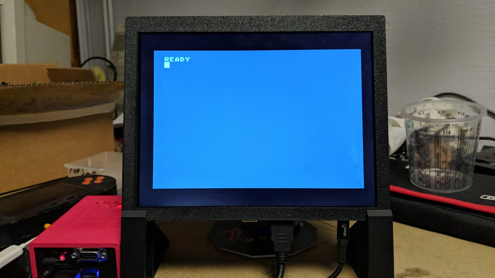
First screen build
I’ve done some research and found plenty of LCD screen controllers available these days. Immediately, I was like … little screen for retro computers!
eBay is full of such controllers. Some are even sold with iPad replacement screens.
I’ve ordered two different controllers with an additional iPad LCD but more on that later.
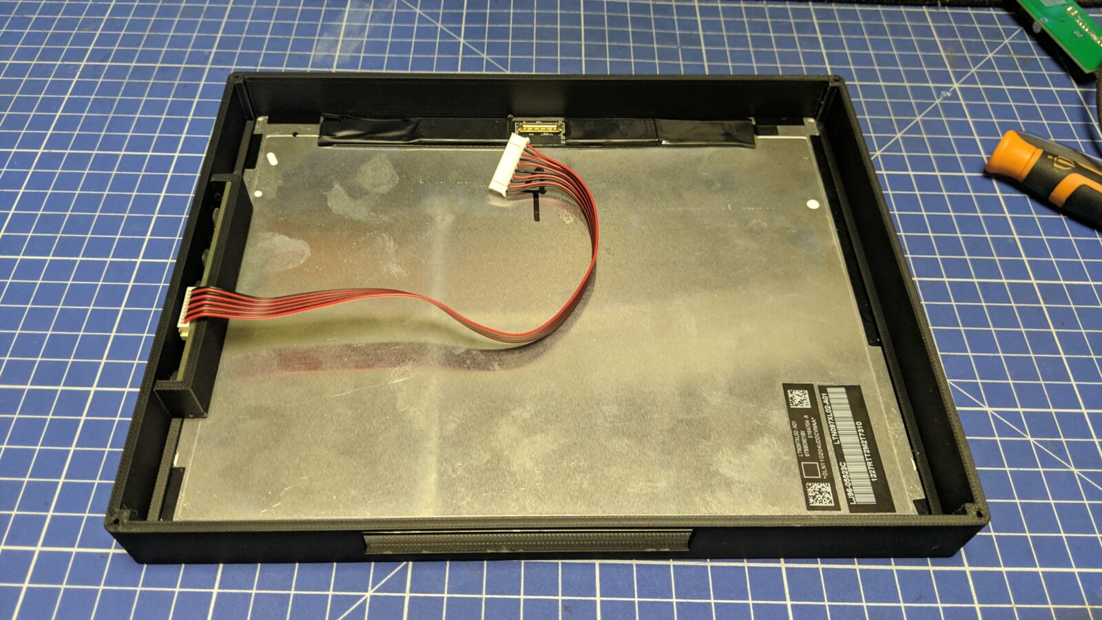
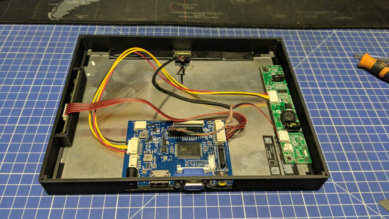
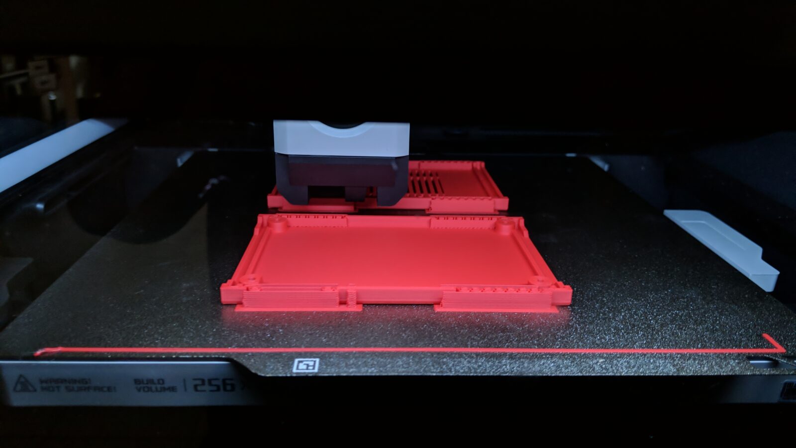
I’ve started to design a case for it which I later can 3D print. Unfortunately, I didn’t take all the pics documenting the first build. However, I have some pics of the already 3D-printed case where I started to put all the gear.
The idea for the first screen was to make it mobile. This requires a Li-Ion battery cell, a USB-C charger, and some other add-ons for convenience.
All 3D printing files are available at the end of the blog post.
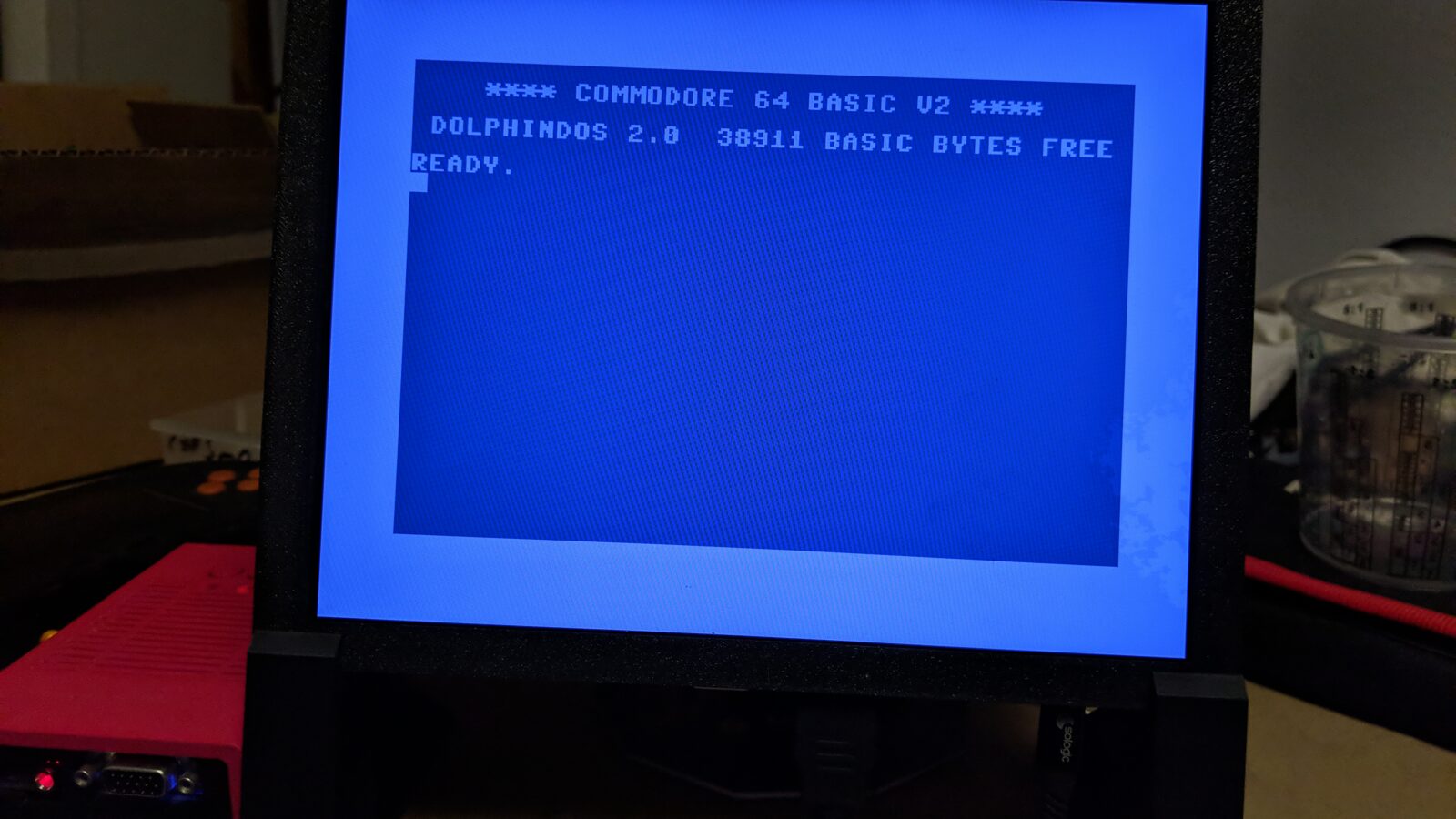
Here is how it looked.
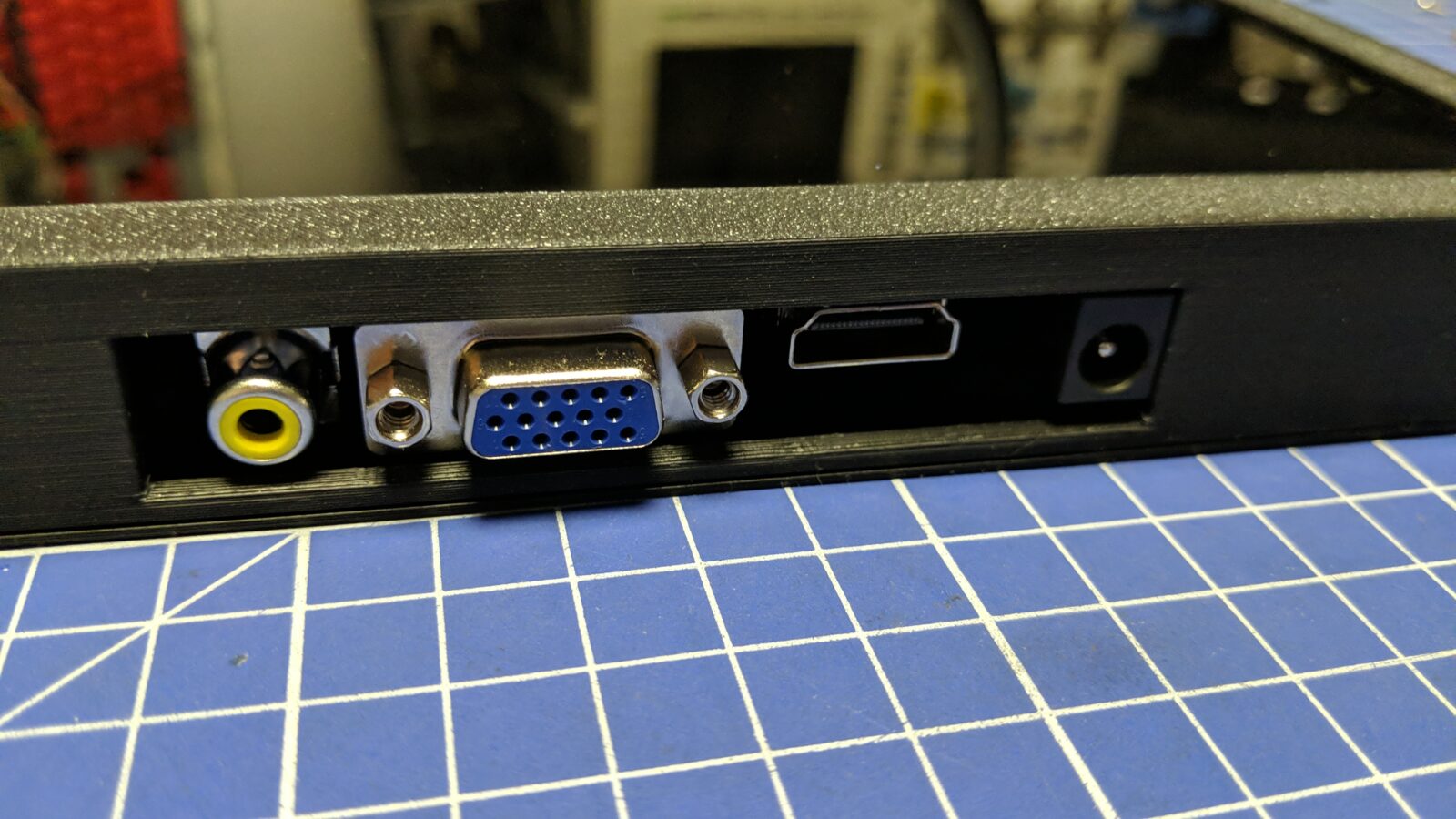
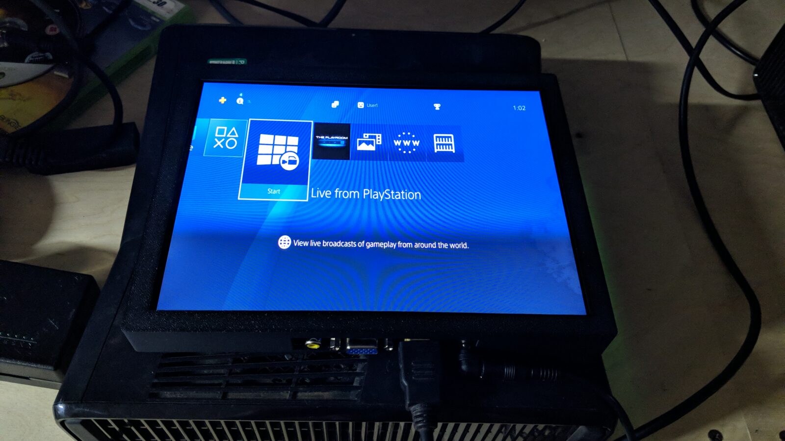
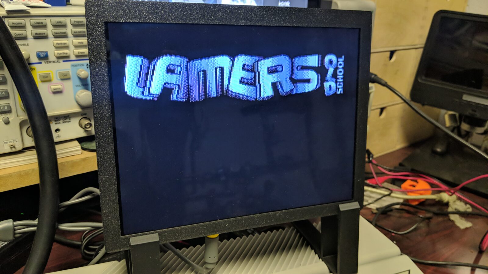
I’ve run some initial tests with PS4 connected through HDMI
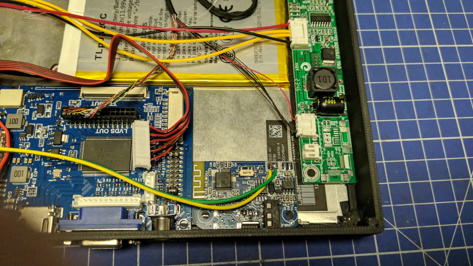
Next, I’ve installed a Li-Ion battery cell, a charger, a DC-DC converter, and a main switch.
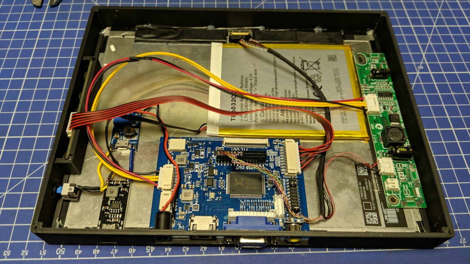
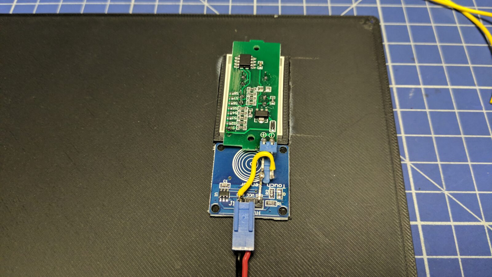
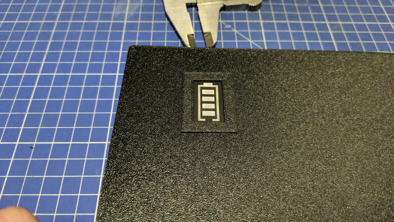
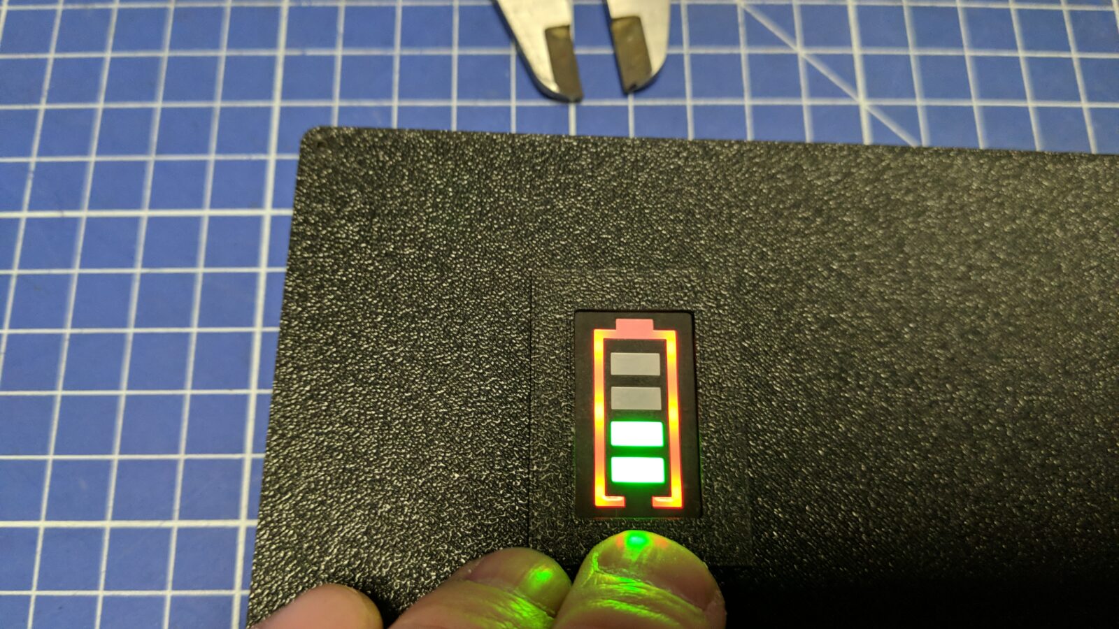
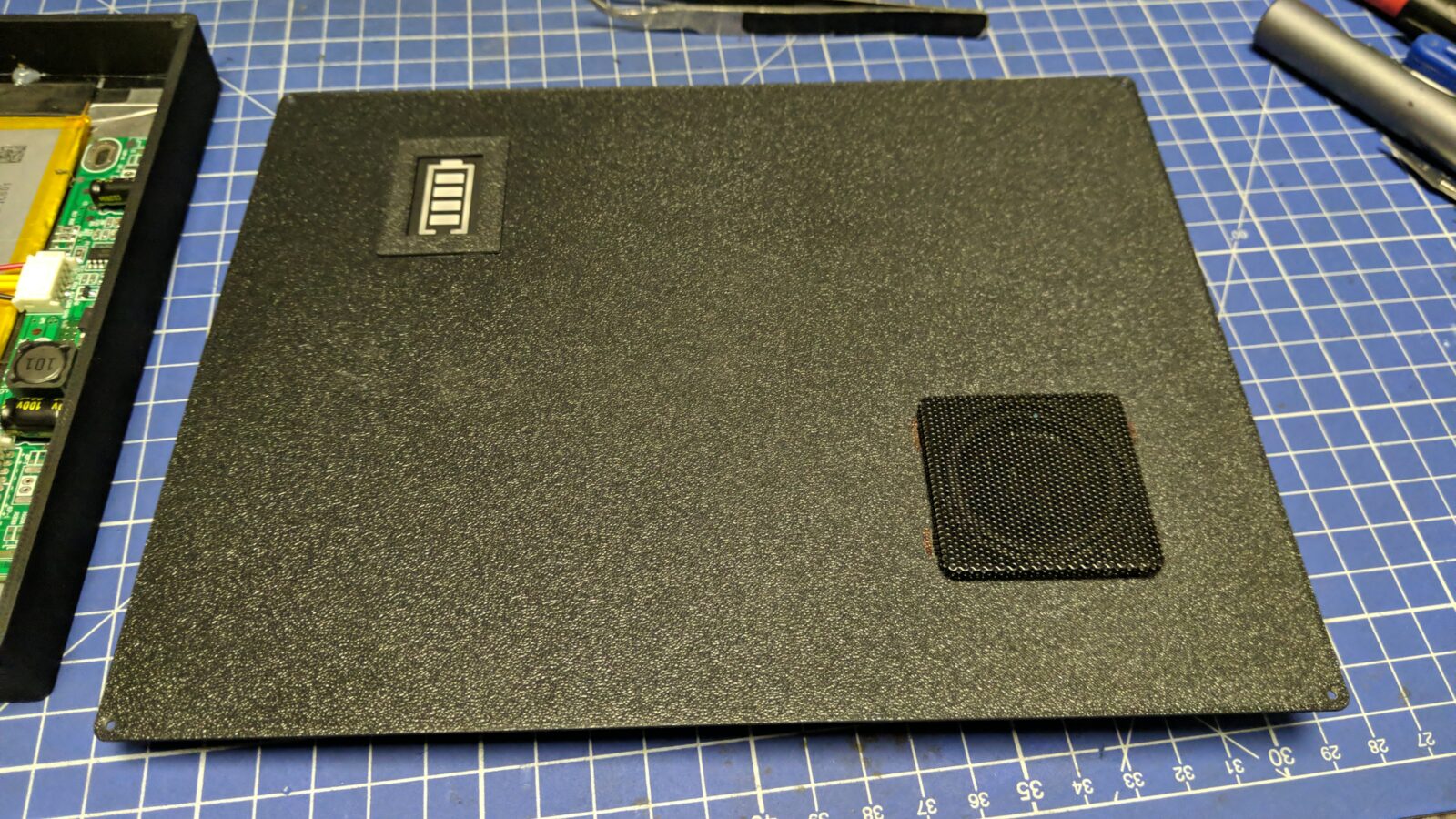
At this stage, I also added a touch-controlled battery LED tester. I didn’t want it to draw power all the time so it only lights up if the capacitive sensor senses a finger on the outside shell.
Next, I’ve added 3D-printed legs to it.
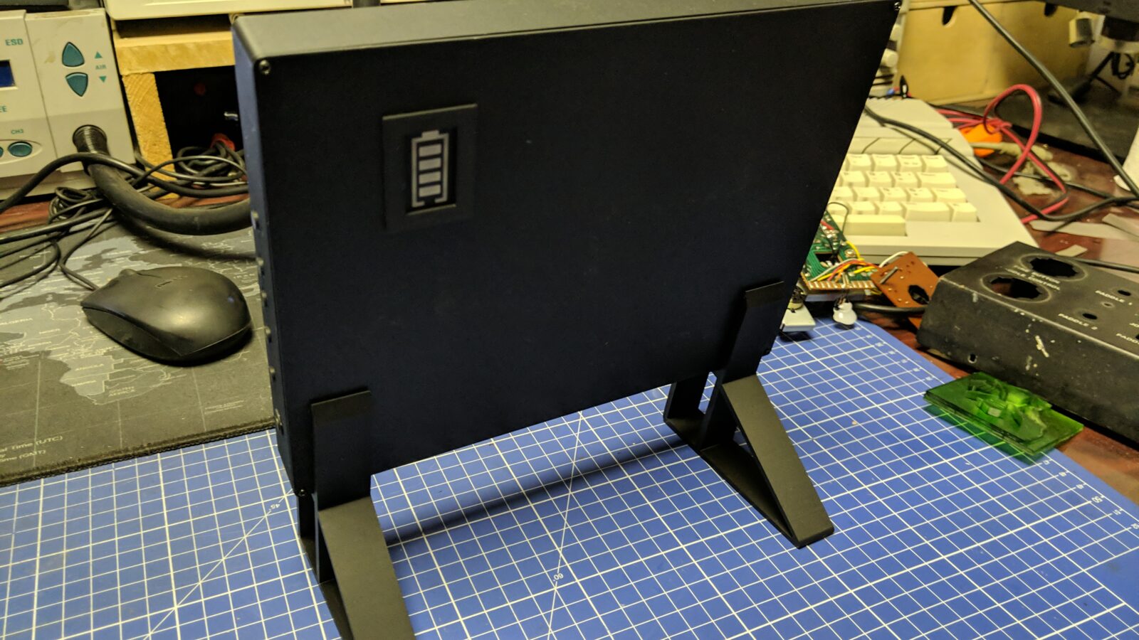
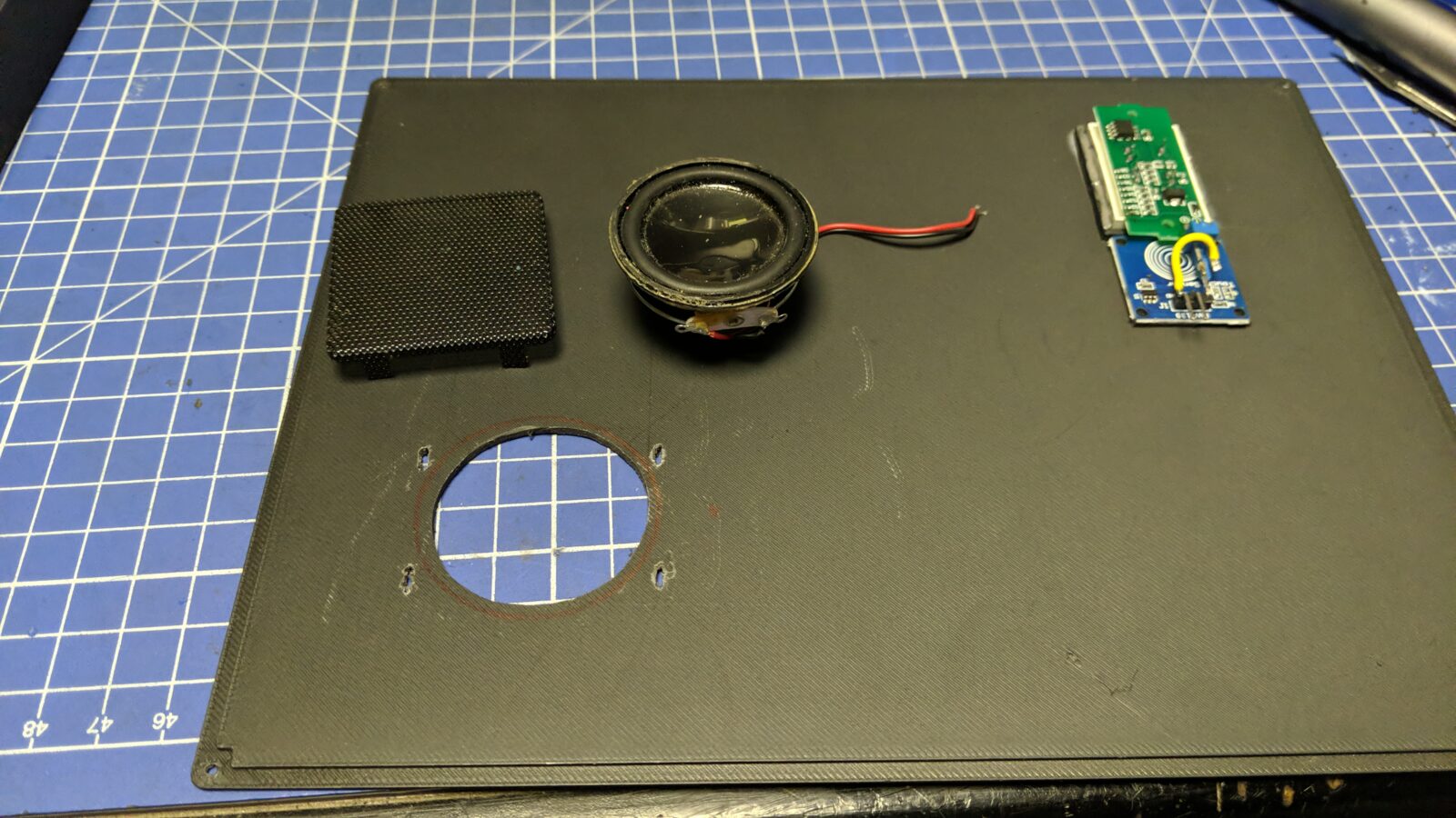
Finally, I’ve used a circuit board from a tiny BT speaker and the speaker itself and mounted it all inside.
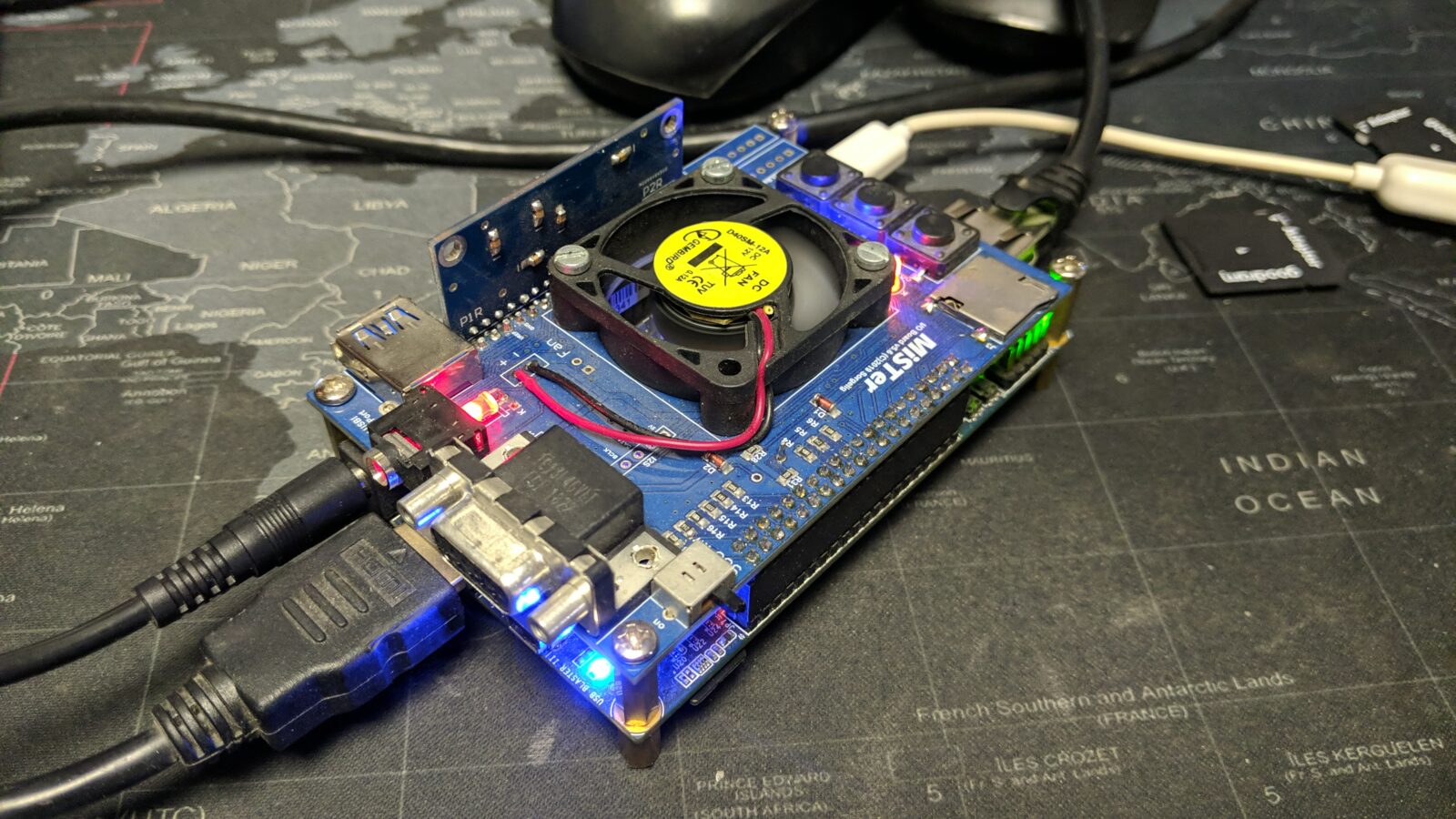
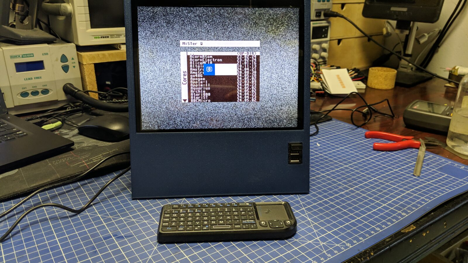
The MiSTer build
Well, to be honest, it’s not a build, as this was already assembled and tested before (and left to be covered with dust:). However, I needed to 3D print a nice case for it and test it with the freshly built screen.
I’ve used a model from thingiverse.com – MiSTer XS Case v2 for SDRAM XS – extra slim v1.1
iPad LCD – second build
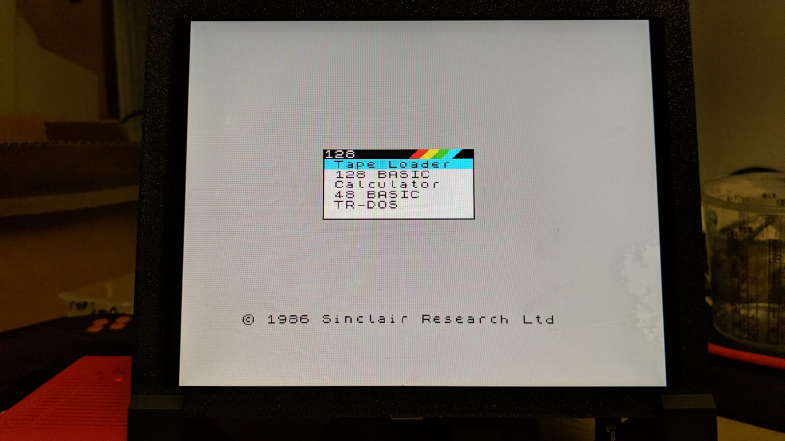
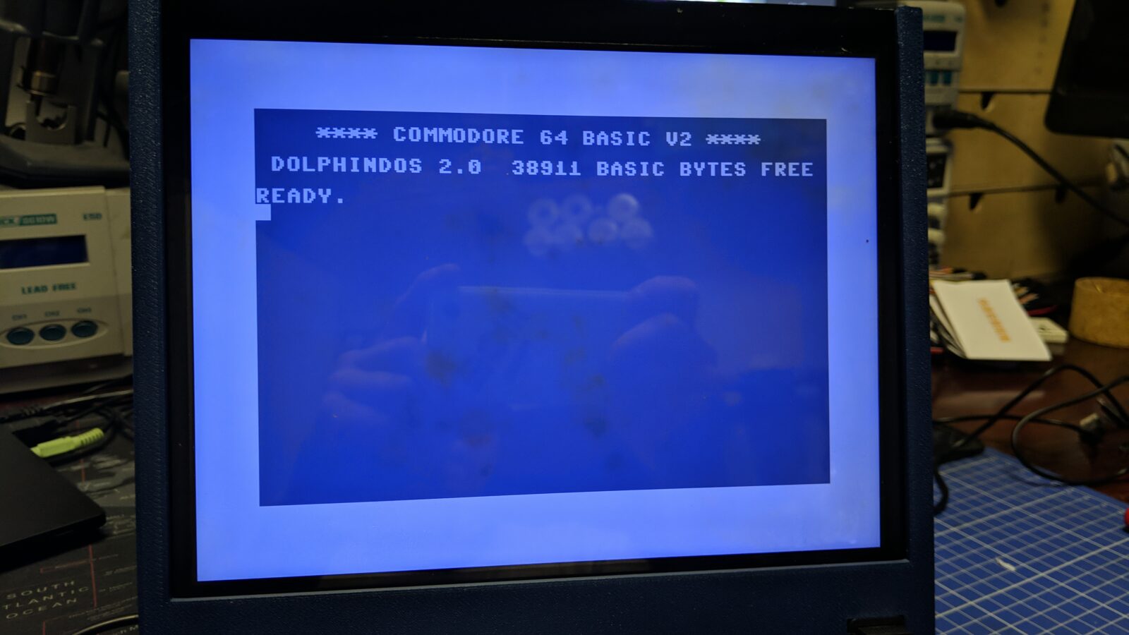
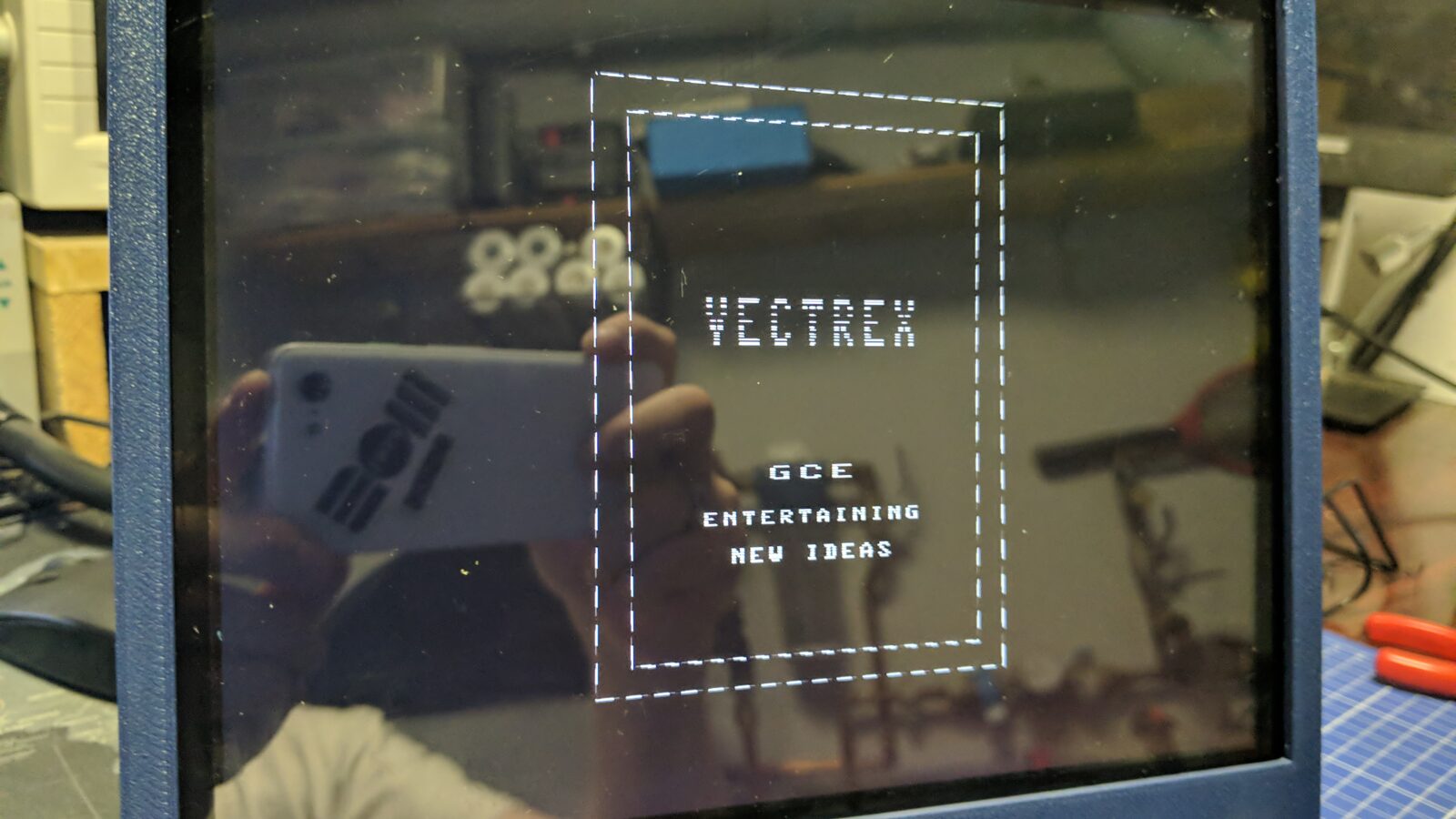
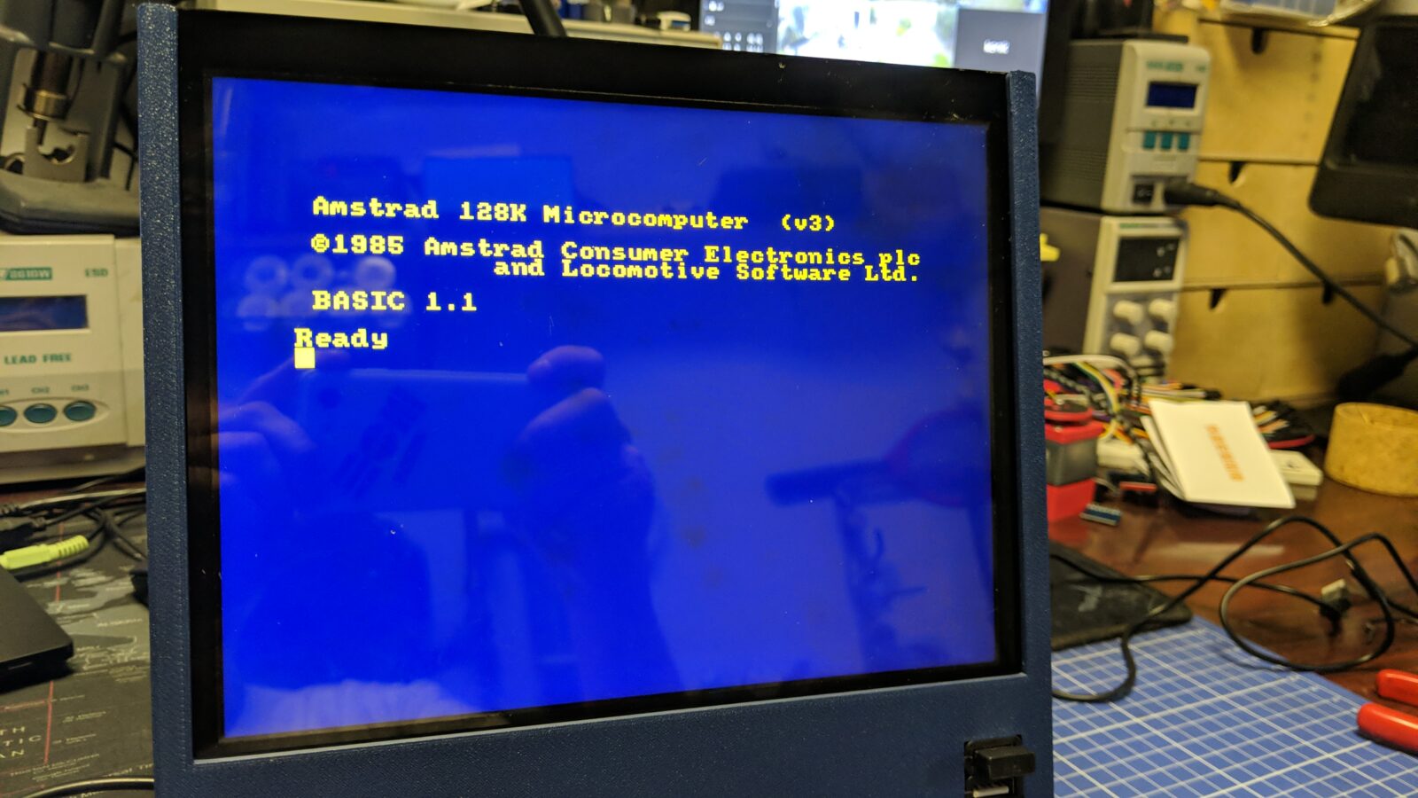
After playing a bit with the first LCD, I’ve figured that I can use it for more than MiSTer (as I originally planned) and it can become my main testing rig for various retro machines as it is lightweight and battery-powered. However, I still needed the screen for the MiSTer, hence the second build.
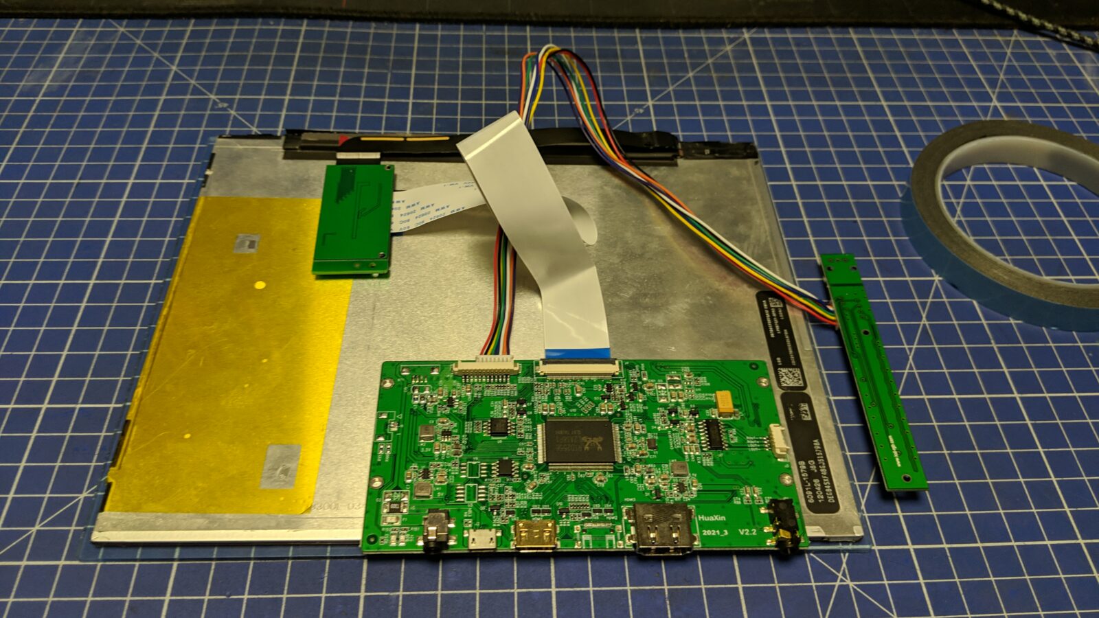
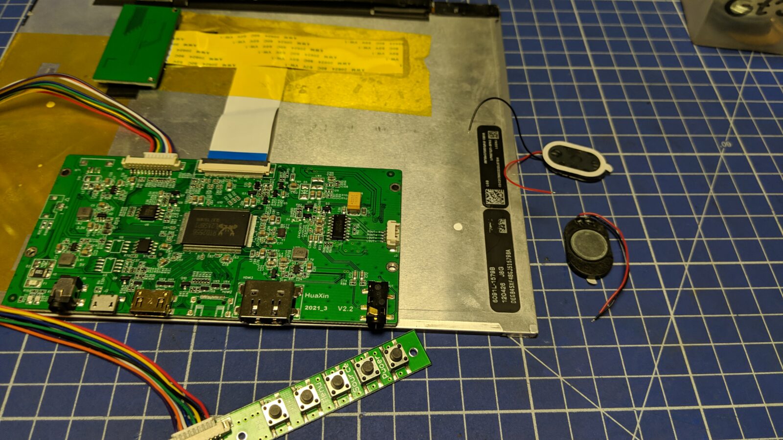
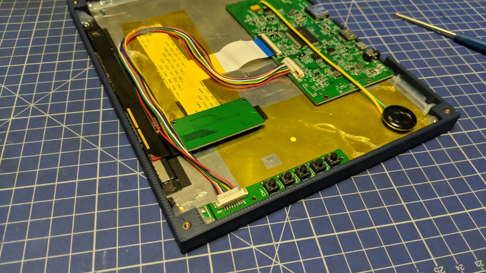
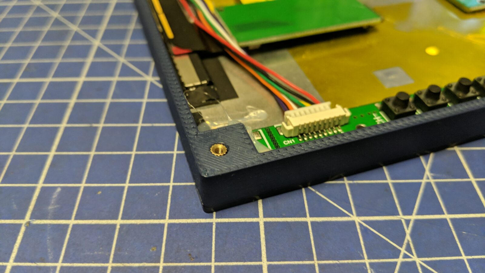
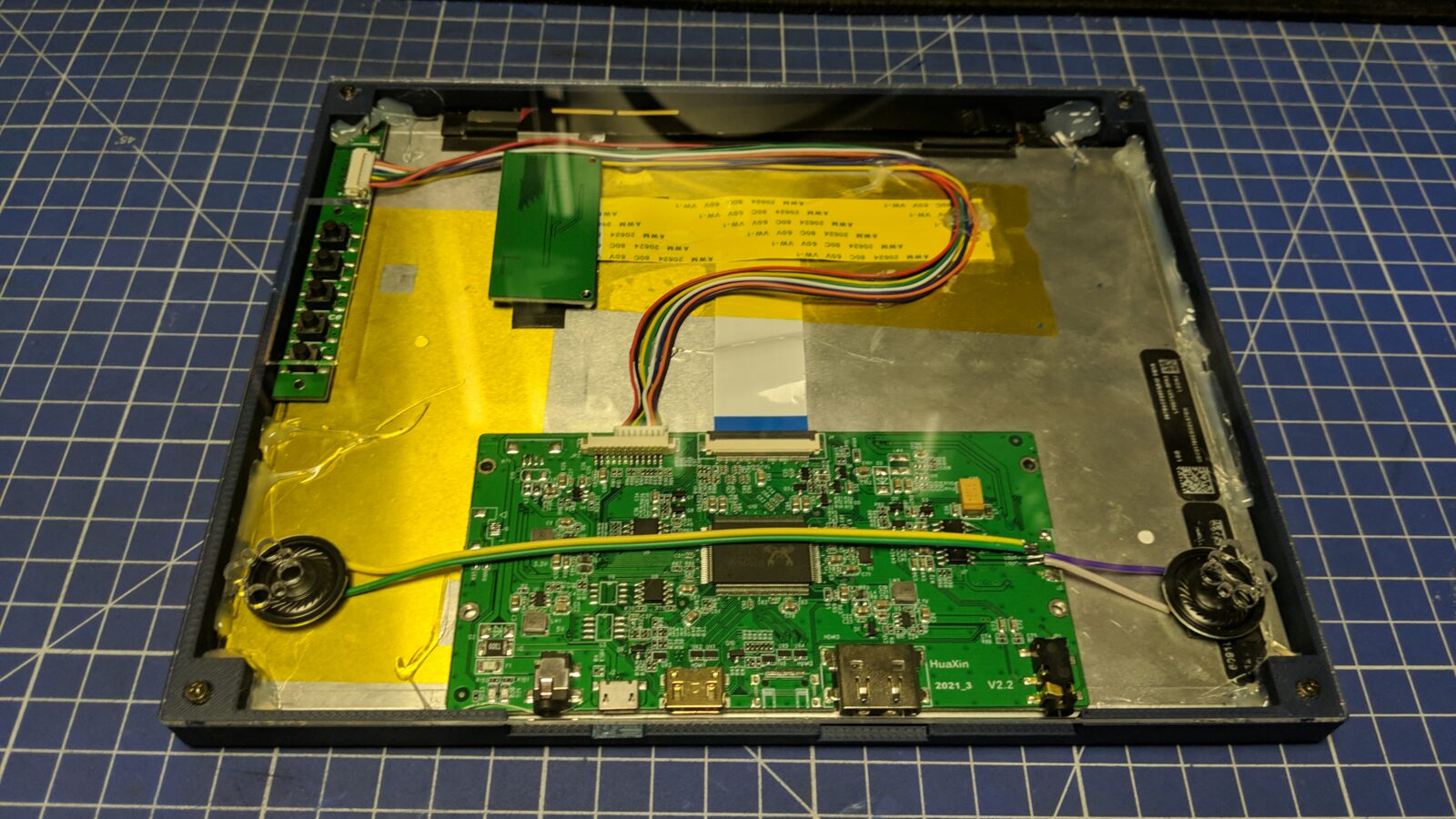
Meanwhile, the second controller with iPad LCD came in. This controller is a bit different. It is also RTL chip-based but HDMI is the only video output available. Also, this PCB has an audio amp on it, so I can directly attach speakers to it.
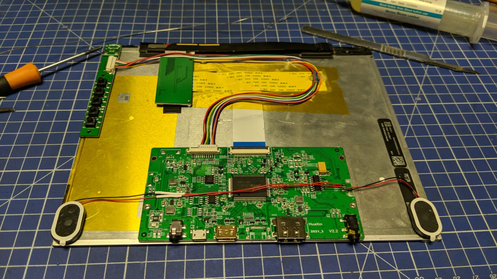
I’ve started to plan the layout.
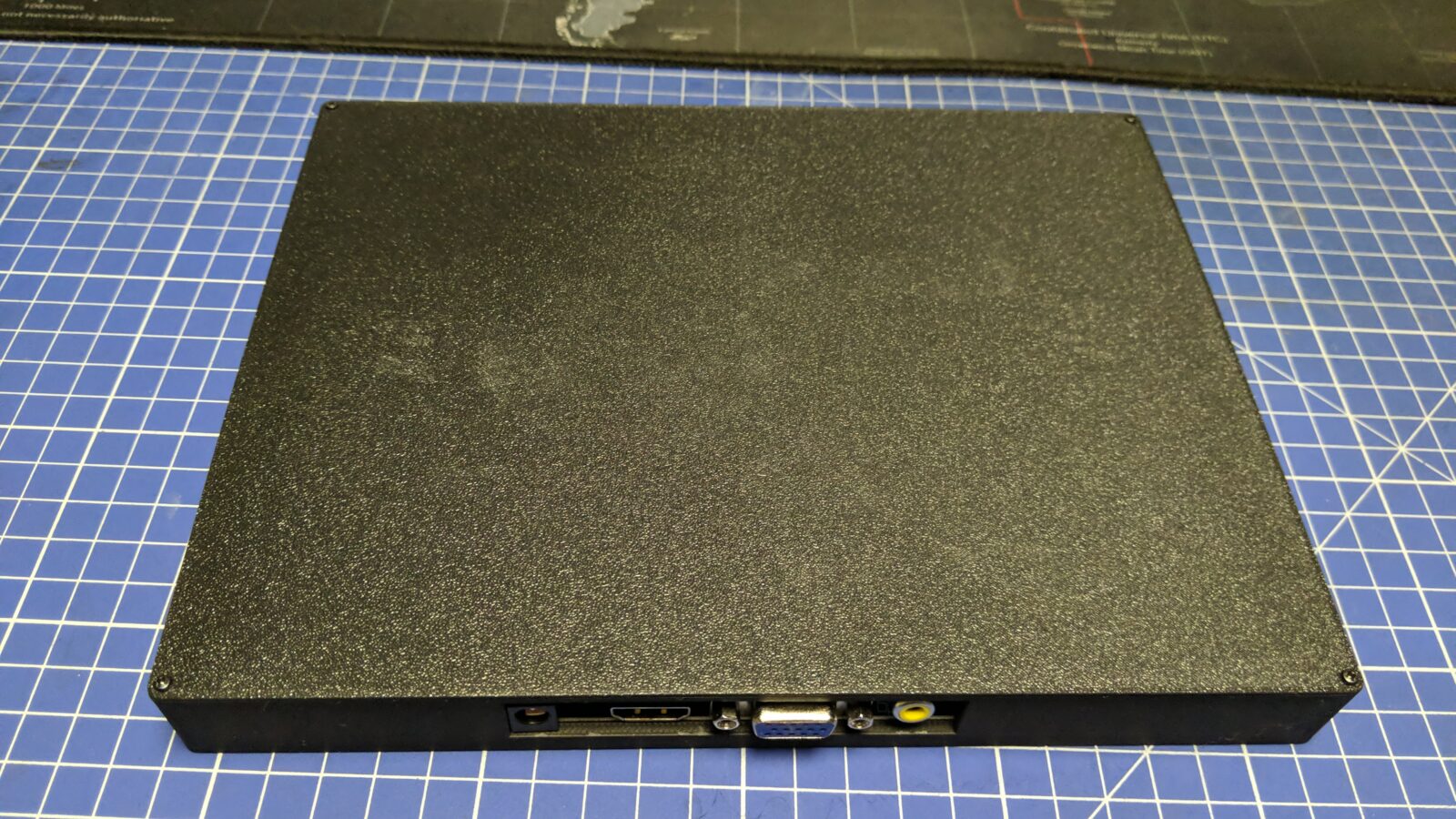
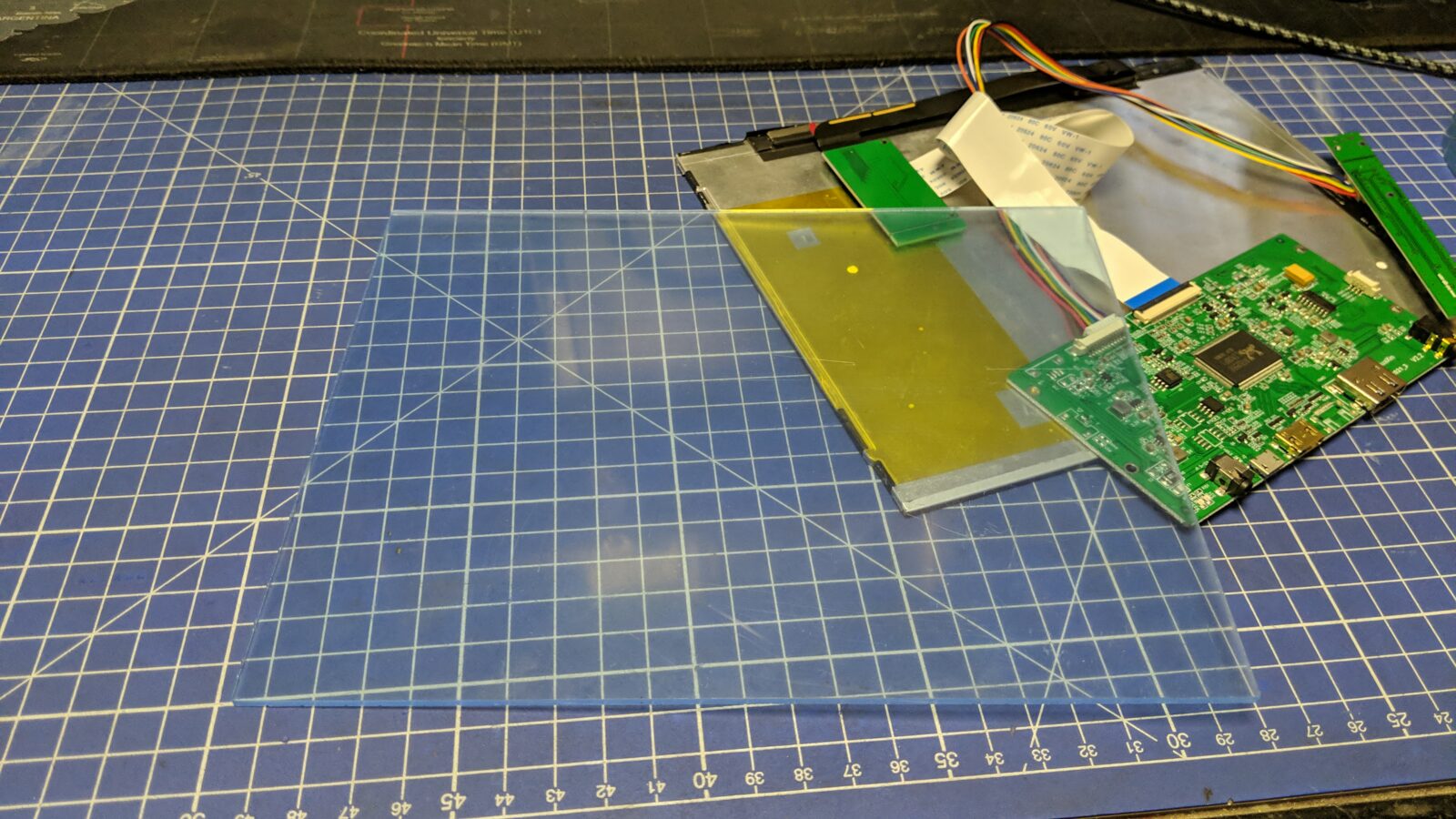
This time, I wanted it to be thinner than the previous build. I also wanted it behind an acrylic sheet which I laser-cut.
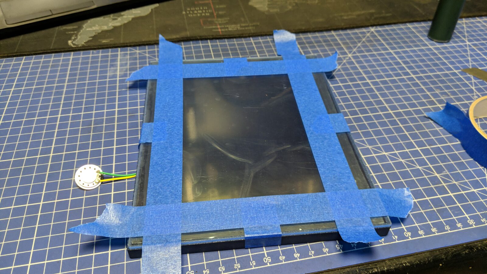
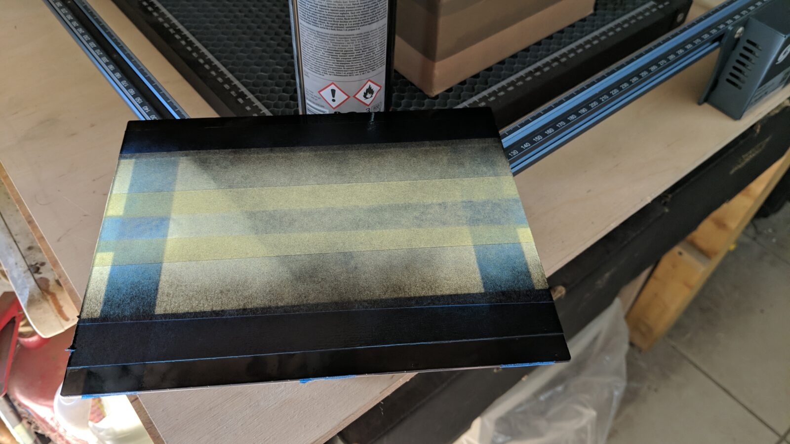
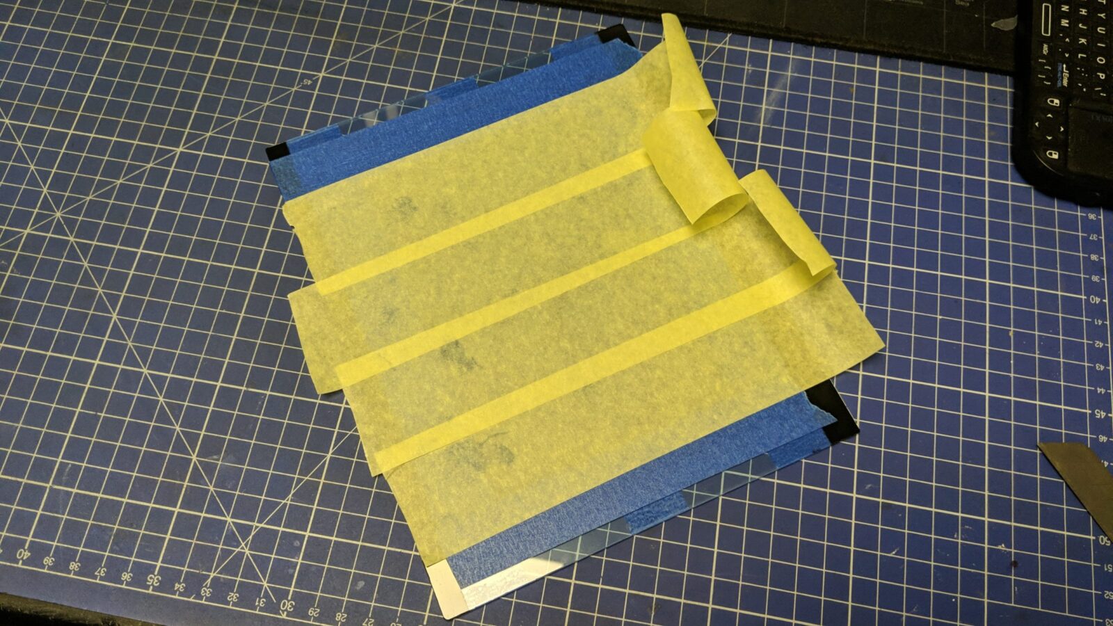
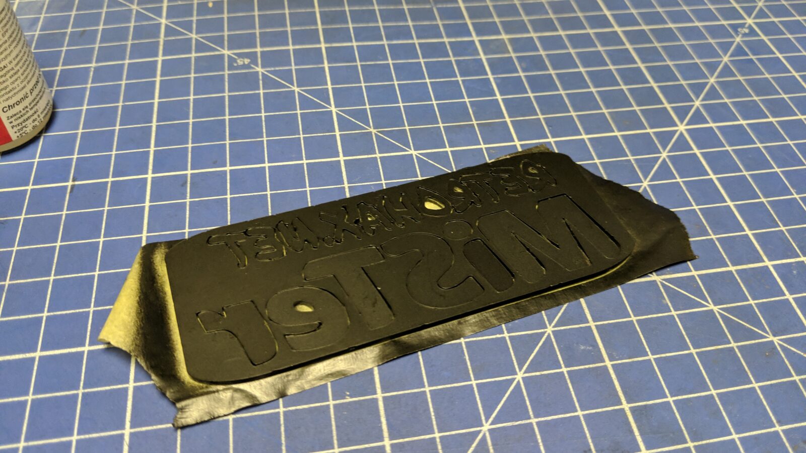
To make it look nice, I had to cover the edges with black paint on the inside. I’ve used some paper tape to cover the display area. I had to do two rounds for vertical and horizontal edges respectively.
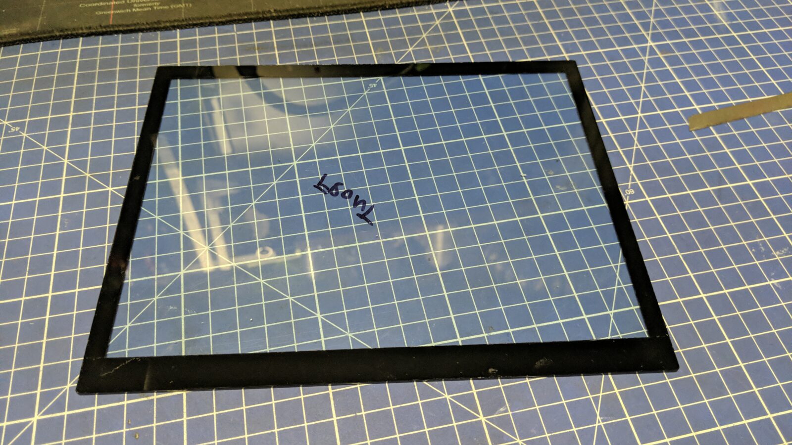
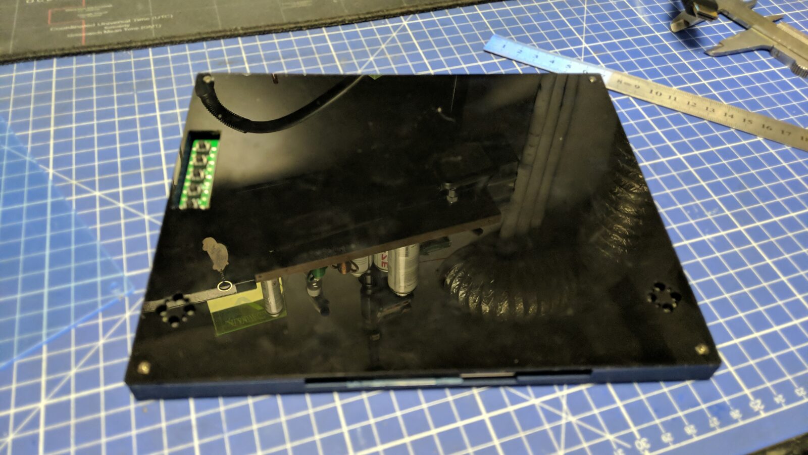
Once the part was ready, I applied a double-sided adhesive tape on it and glued it onto a previously designed and 3D-printed outer shell which already held an LCD.
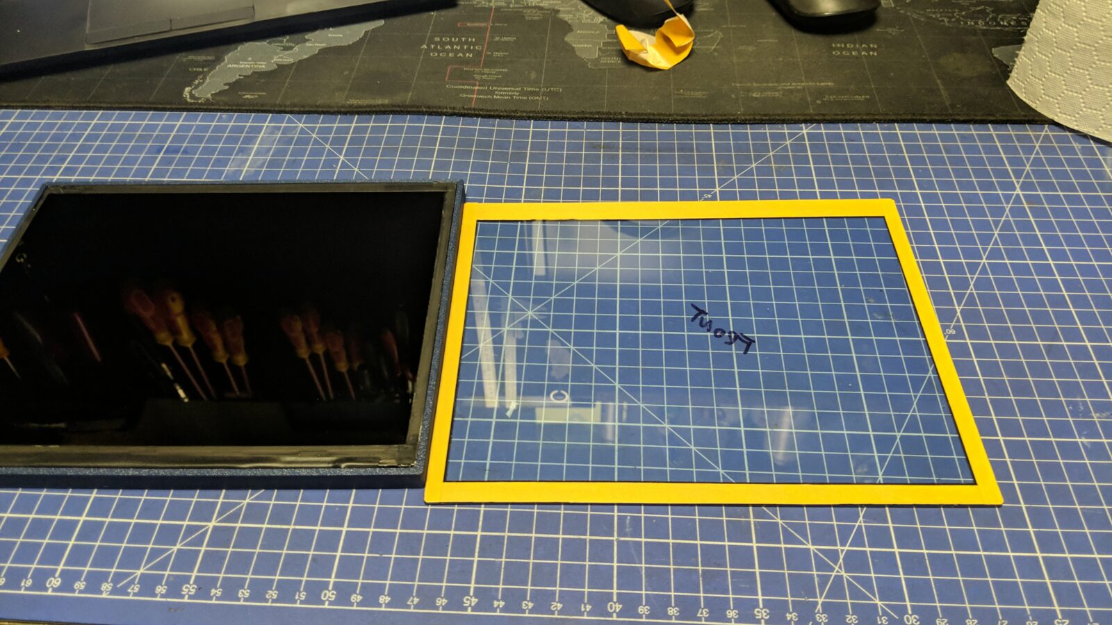
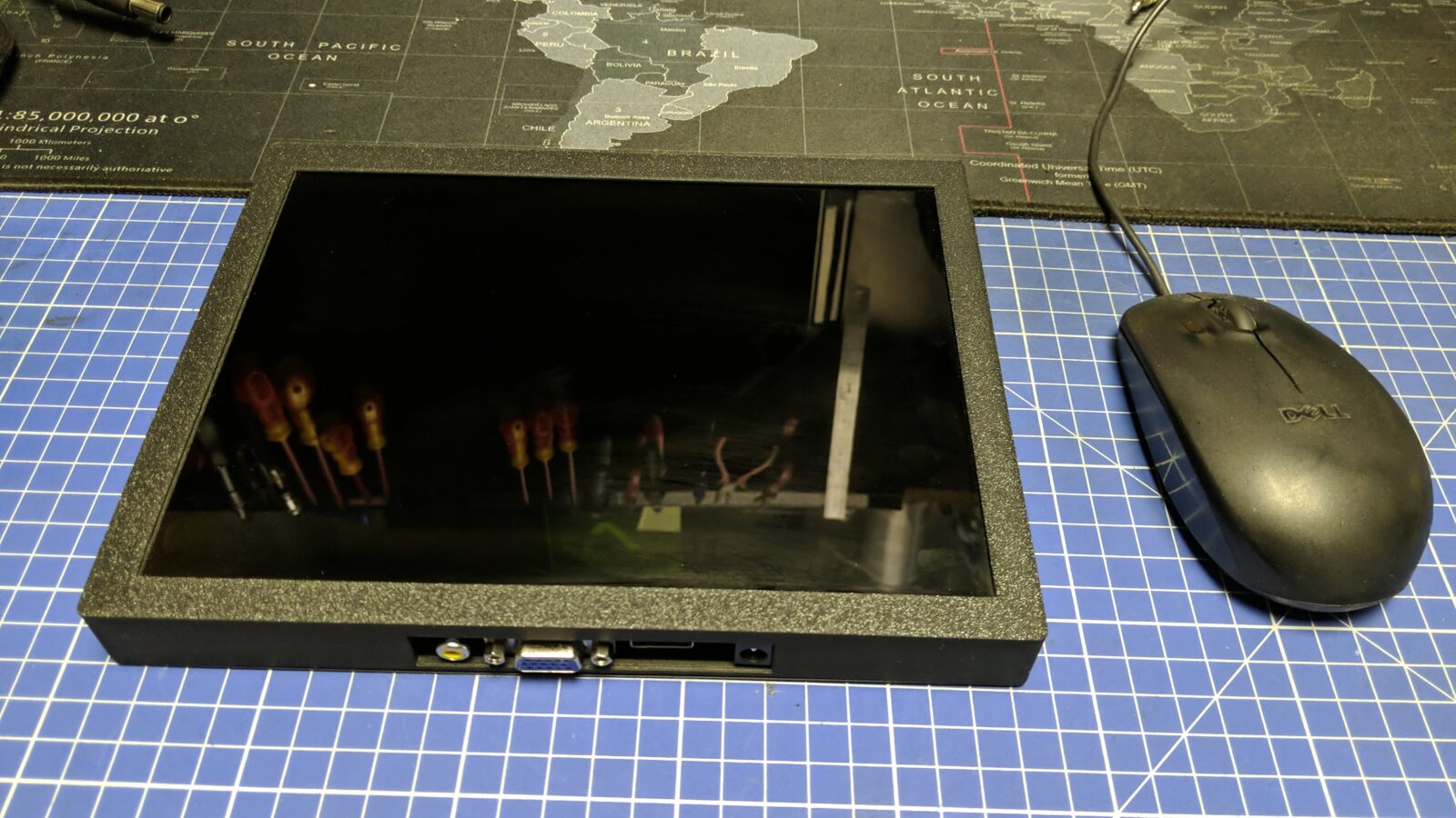
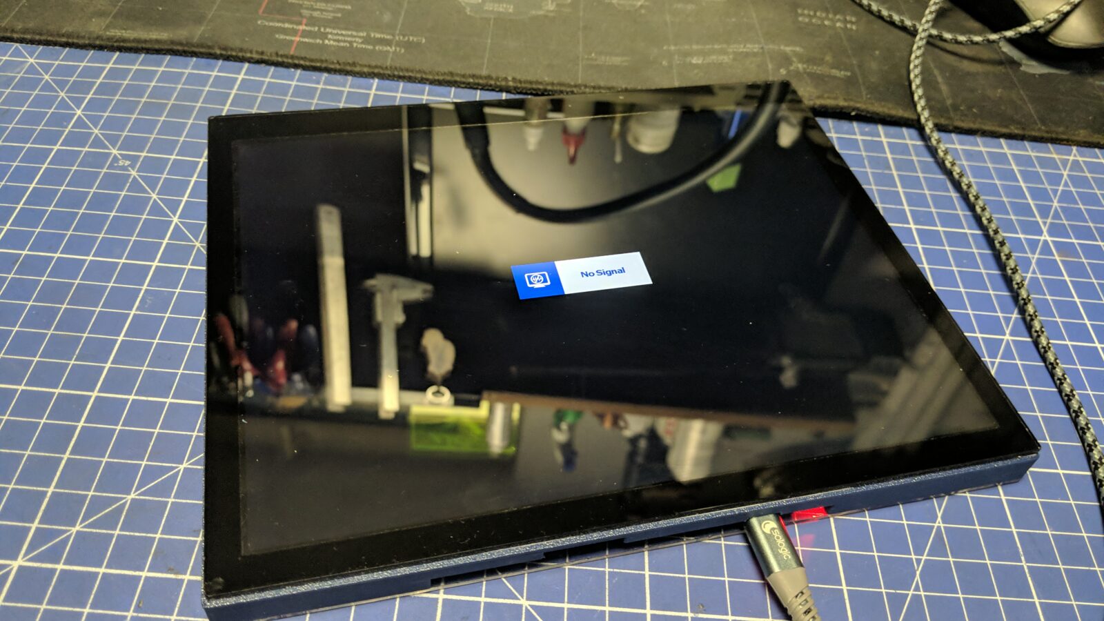
Below is the result, although acrylic is still covered with a protective layer.
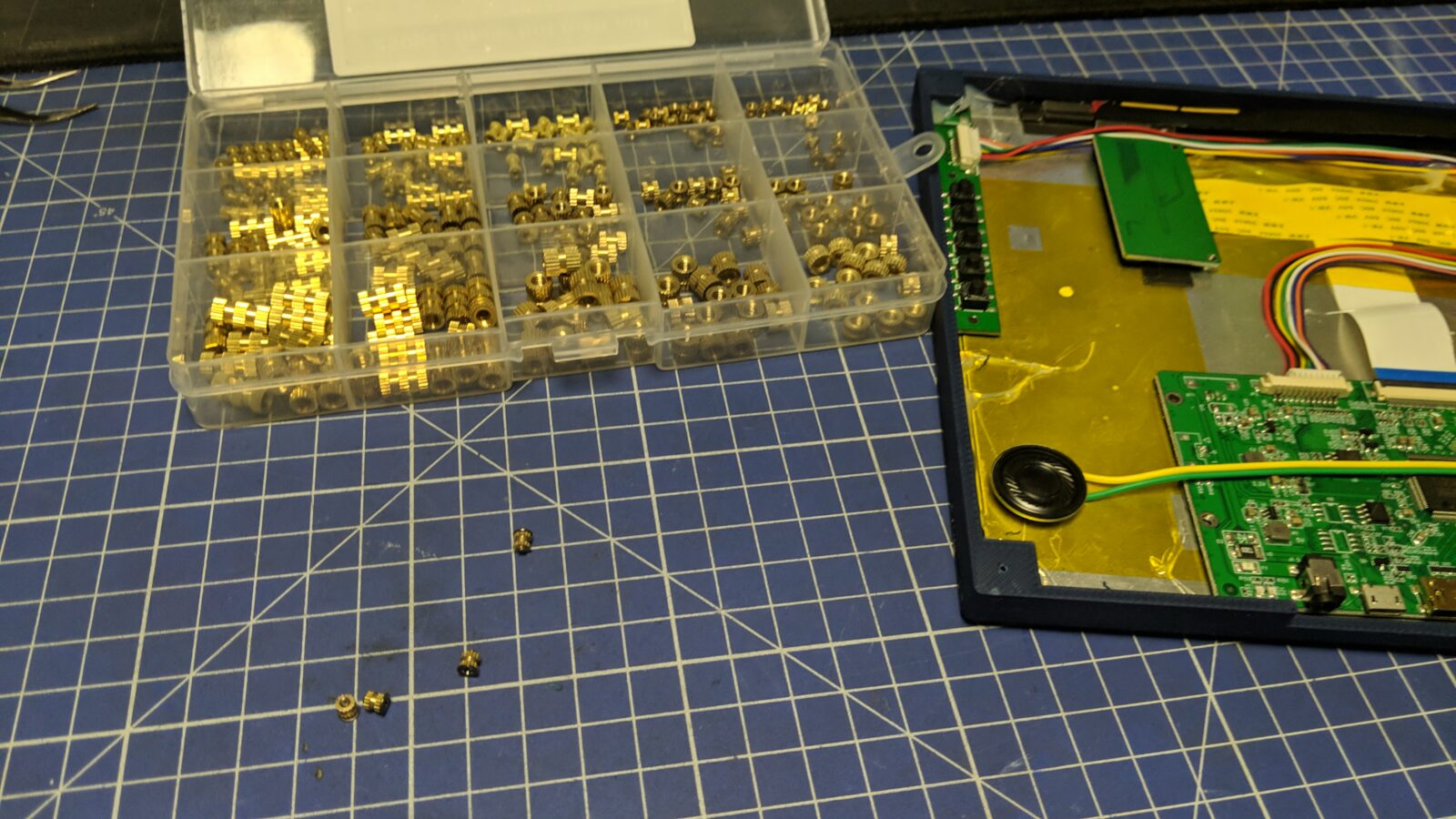
Next, I could take care of the inside. This time, I prepped some screw inlay inserts to keep the back acrylic in place with nice screws.
The back side (another acrylic sheet) was laser-cut and painted black later on.
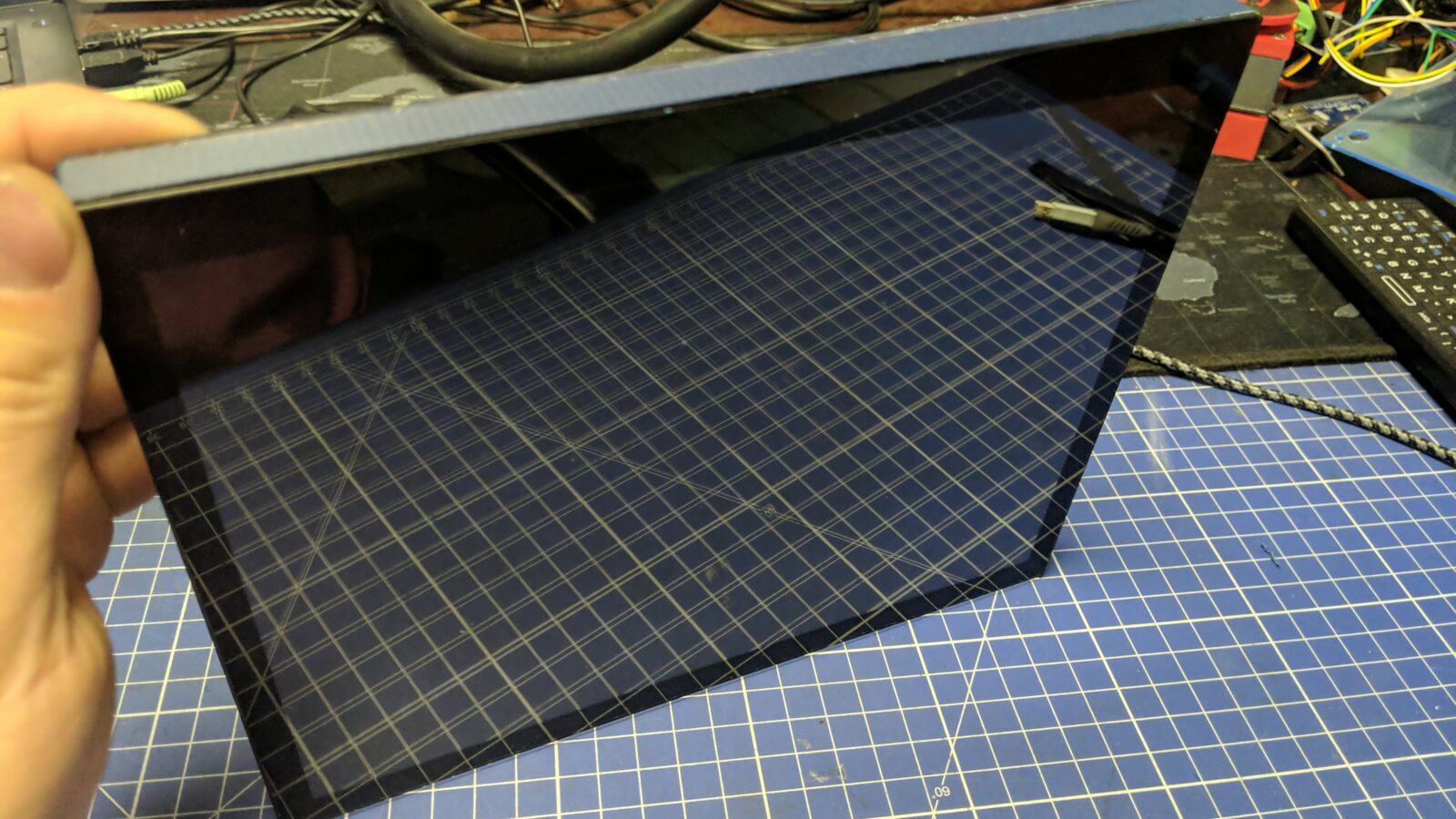
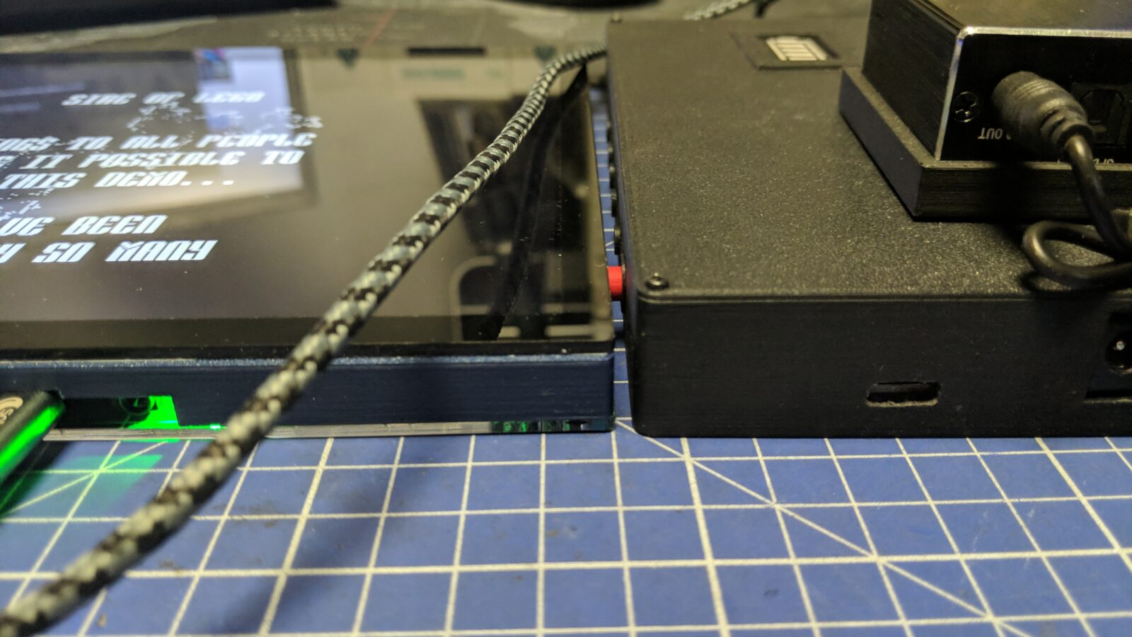
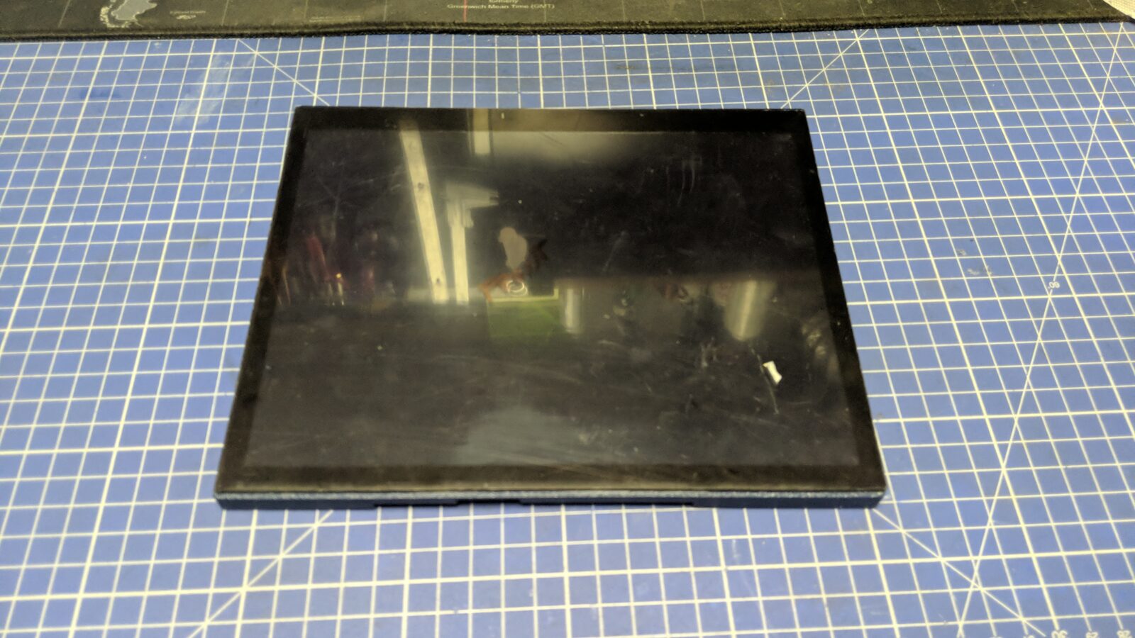
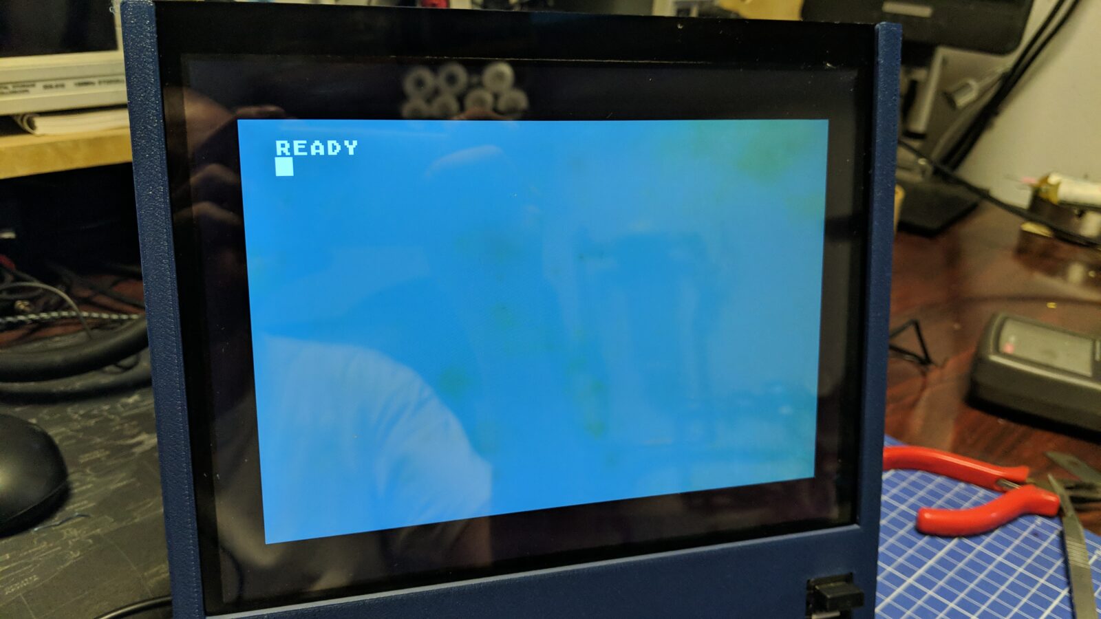
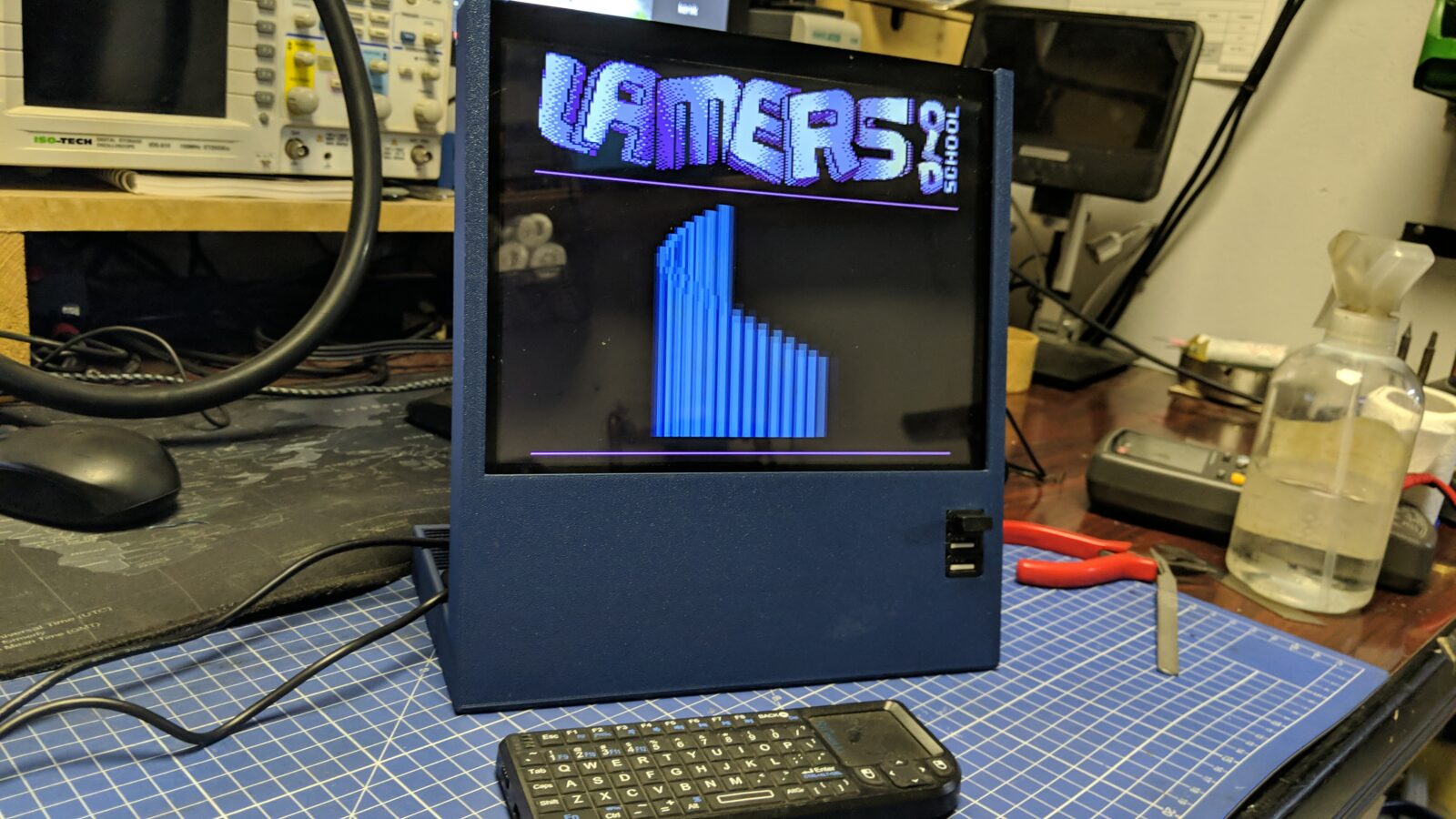
I’ve run some tests with it and unfortunately, it turned out that the LCD that I bought along with the controller has some inside “stains”. Still, it is a pretty good screen, so I decided to keep it.
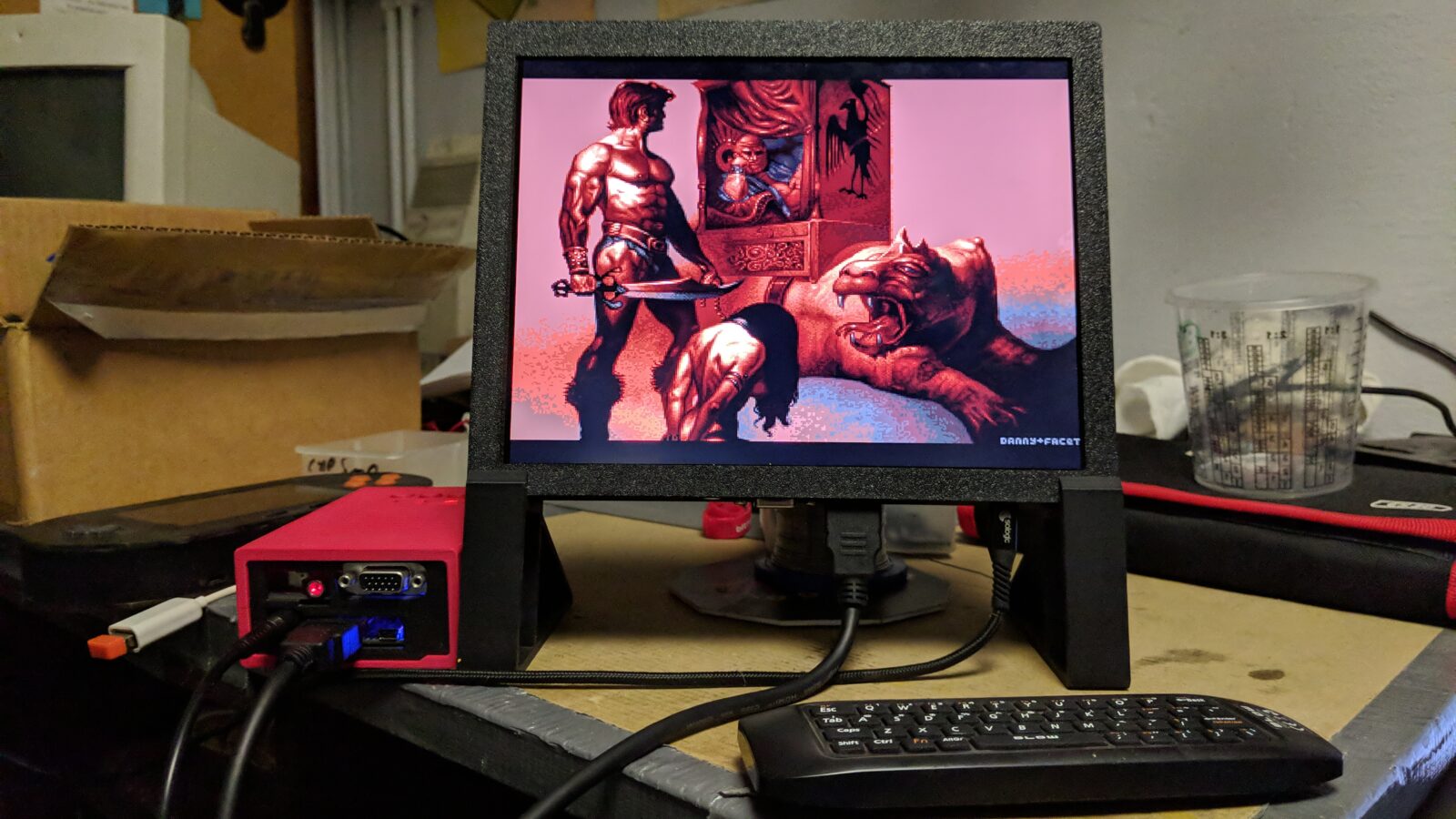
The final setup
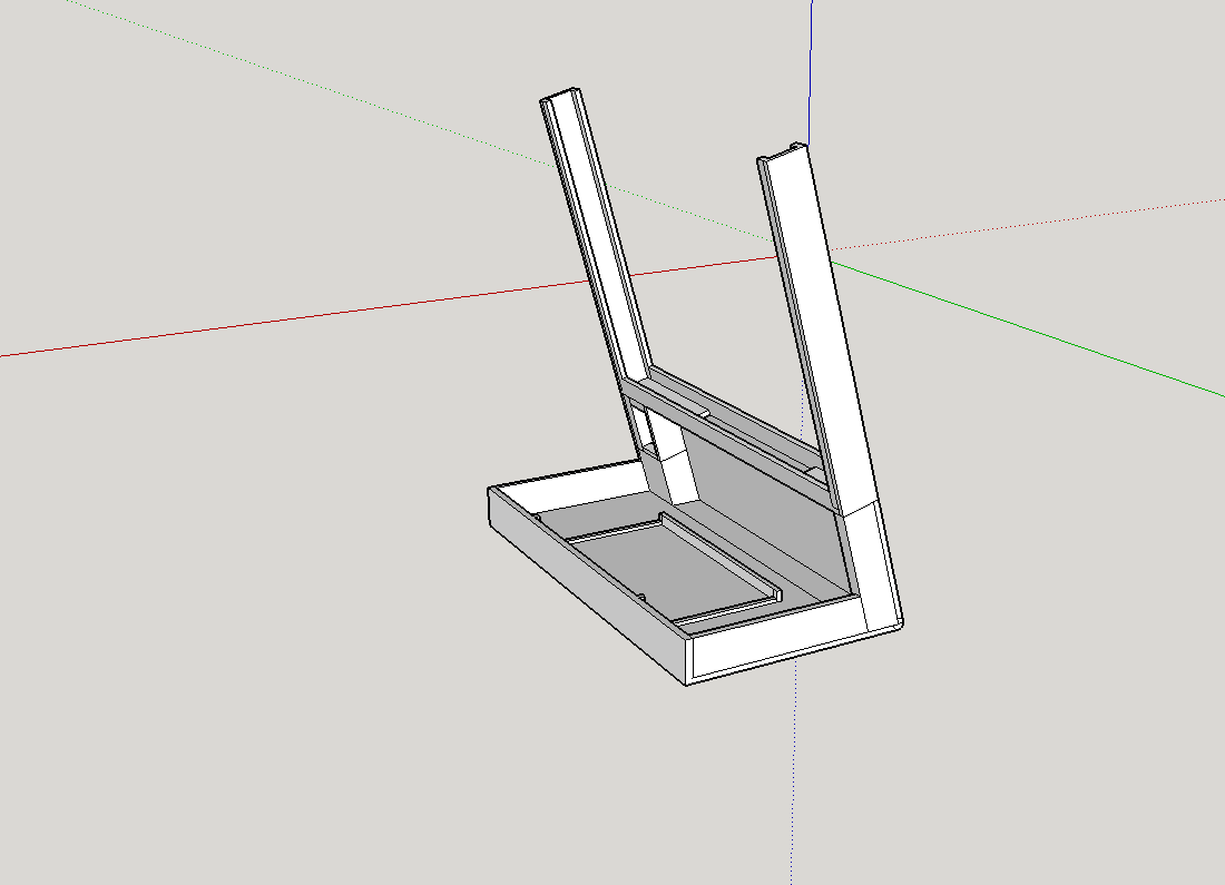
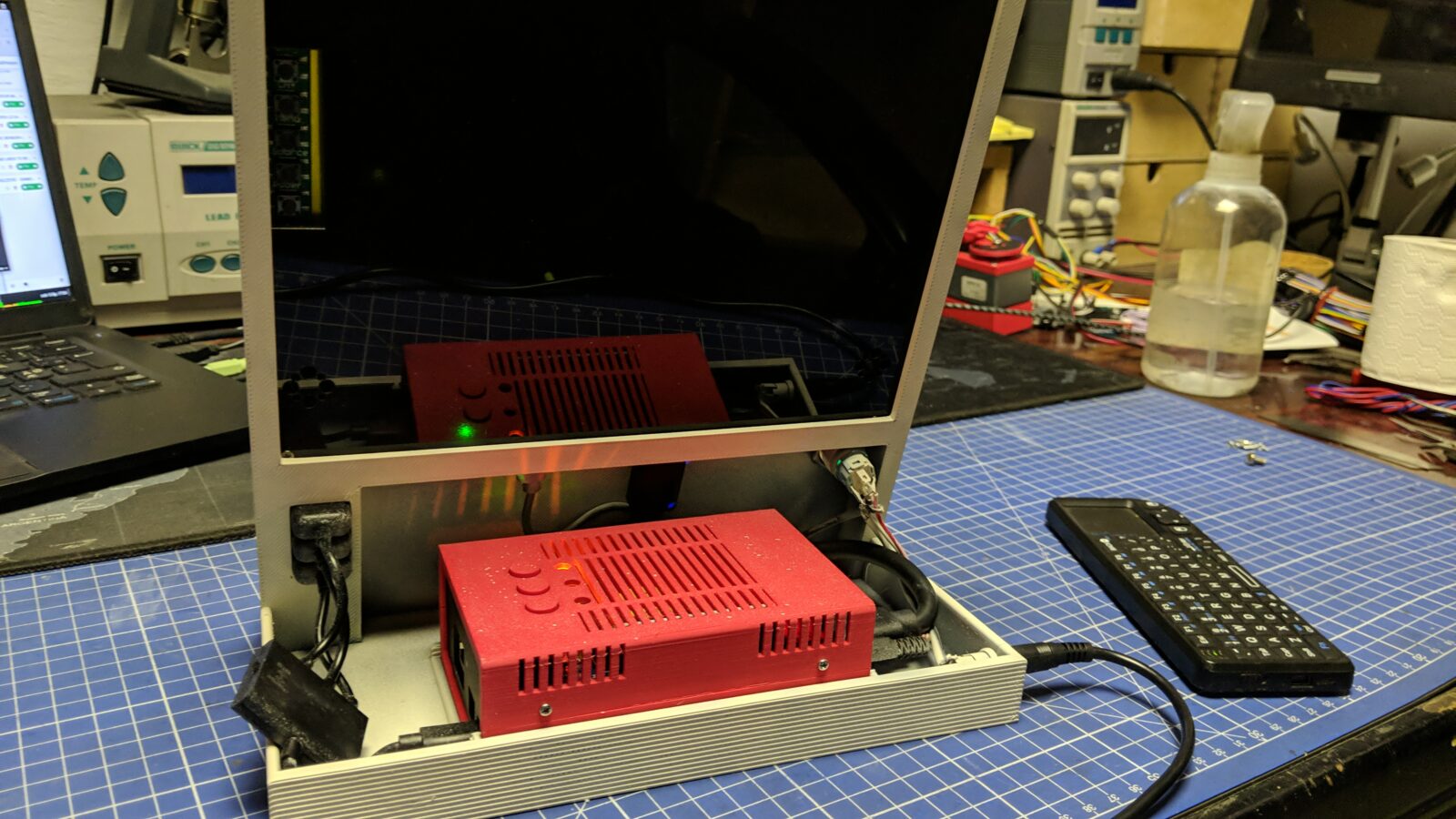
With all the hardware components ready, I moved on to designing a final case for the whole setup.
It took a bit of modeling and 3D printing work.
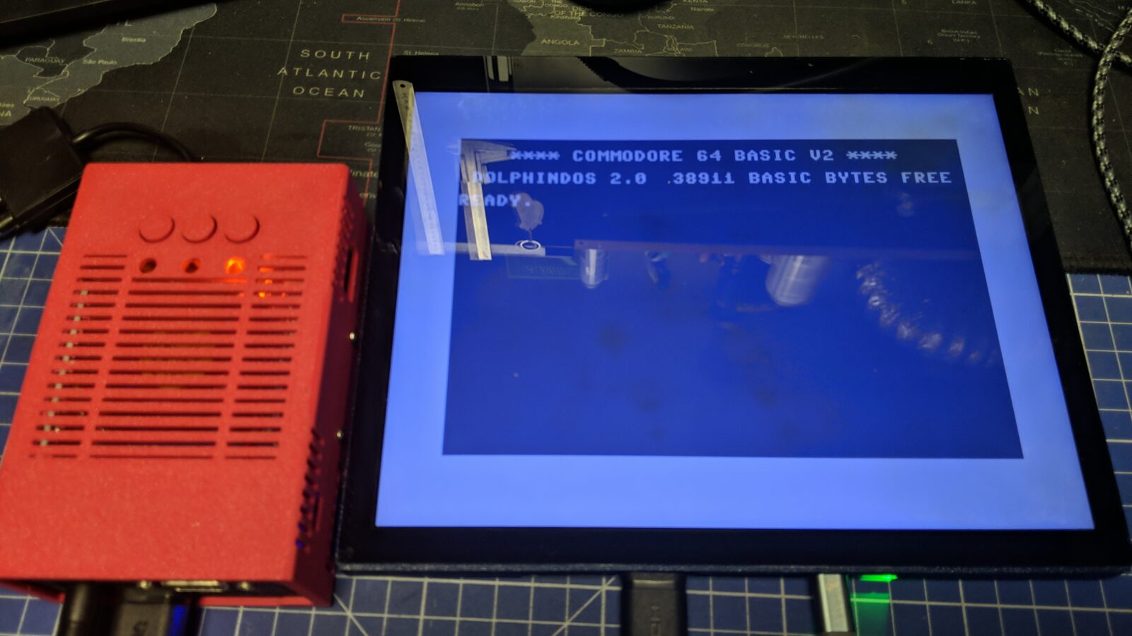
The idea was to put the cased MiSTer on the back and slide in a freshly built LCD. I’ve also added a USB hub just below the LCD.
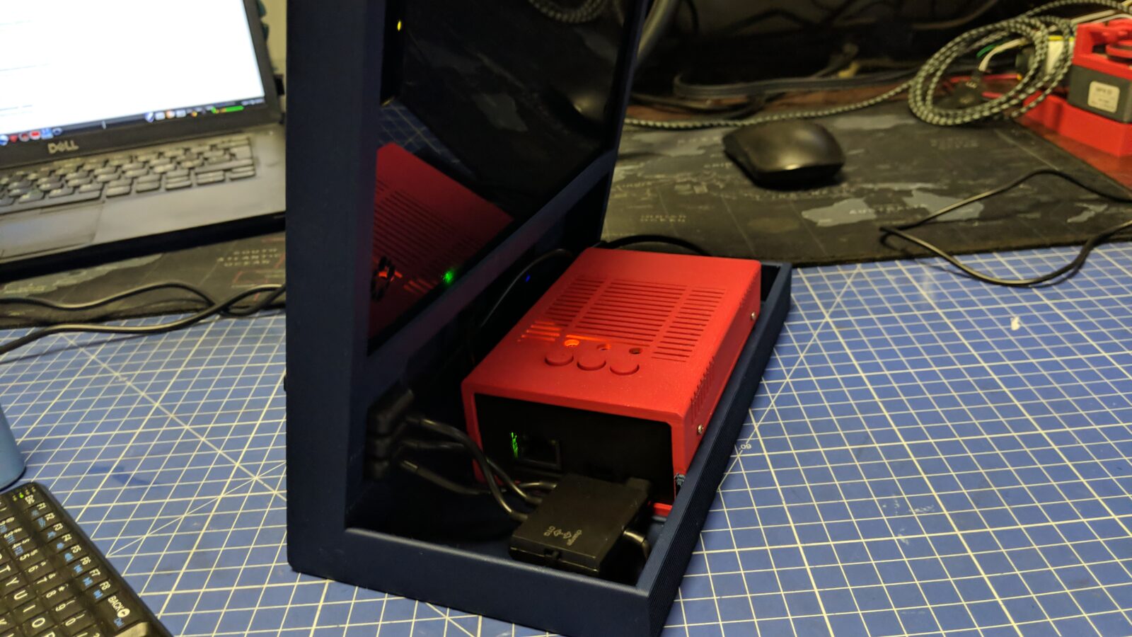
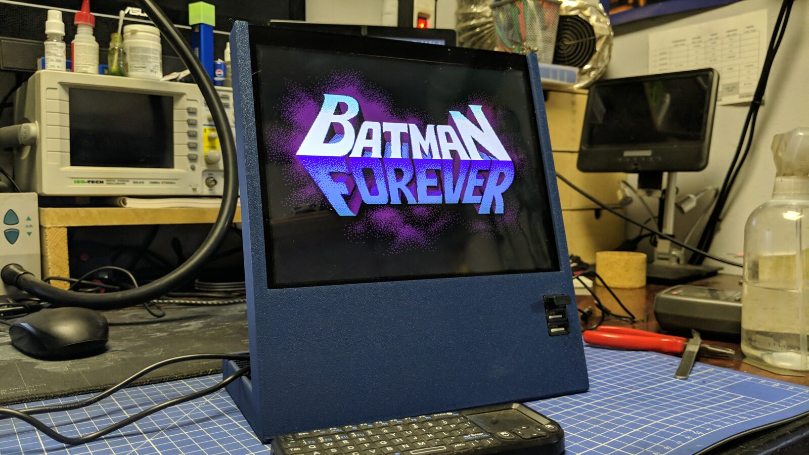
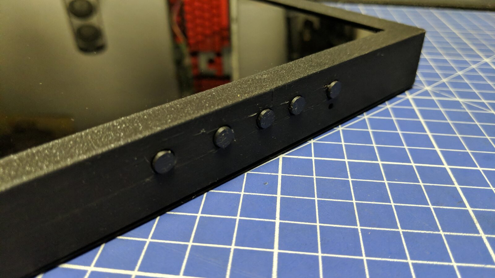
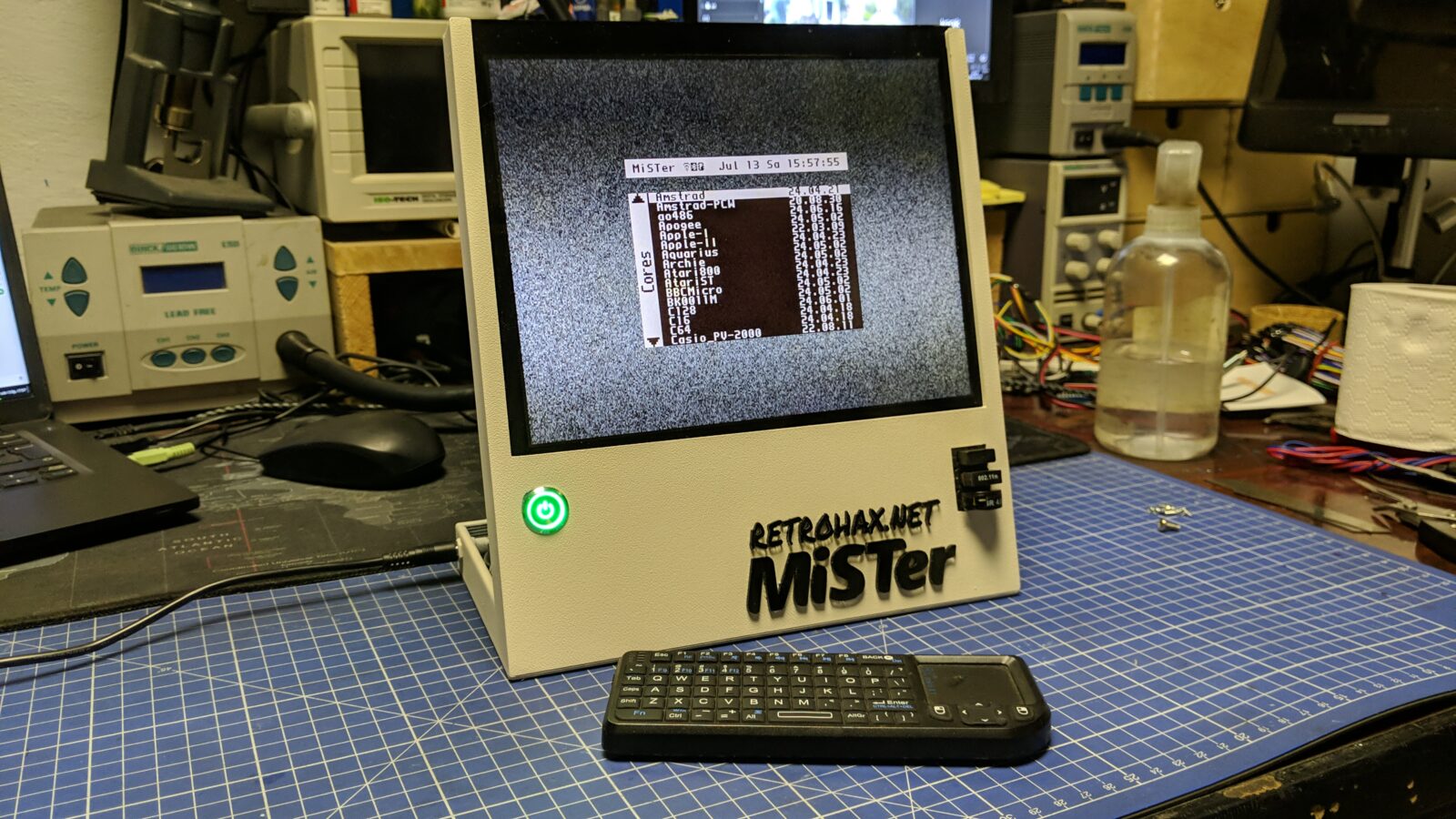
As a final touch, I’ve painted the case beige and added a power button and a laser-cut emblem.
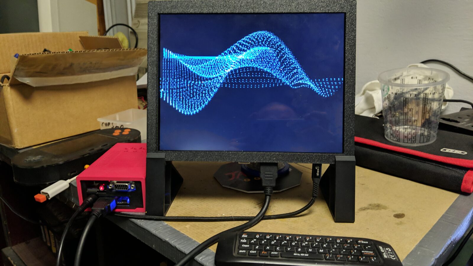
Below is the final result.
STL files for download
See you in the next post 🙂


Coincidentally, I’ve been trying to rehouse my 9.7″ ipad screen from a rather jury-rigged case that was meant for a different PCB.
I found the model you had based your adjustments on (so far as I can tell):
https://www.printables.com/model/692251-case-for-ipad-97-lcdcontroller-board-kit/comments
…and in checking measurements, I have the same PCB as well. But the attached .zip file appears to lack the sides/top/bottom pieces (to which the bezel attaches, with the button holes and such).
It looks like you adjusted some elements – the size on the whole is a little larger and I can see where the corners were reinforced. You don’t happen to have those files as well, do you? I suspect your current zip might only be the newly modified files for the second screen, which would account for only having a few of the stl’s.
Great work on all this. It’s heads and tails beyond what I was planning, but now I’m eyeballing adding a battery into the mix.
Hi Scott,
Actually, all the files are there, although in Sketchup format -> SKP/SKB <- so you can load it in Sketchup and further modify for you needs.
Wow, that printables model is quite similar lol! I’ve made my model from scratch (hence the source files) and the idea was based on those metal cases from aliexpress, also similar but made out of metal.
I stand corrected. I found a copy of Sketchup 2017 and opened it, and there it is plain as day. Appreciated!
Enjoy sir 🙂
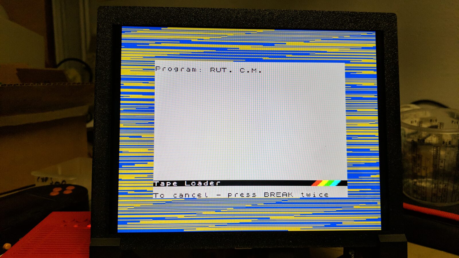
Very nice build. It’s a pity that the panel has a defect. Does the controller support 50Hz input and display it at 50Hz? Some time ago I ordered a monitor from Aliexpress, with 9.7″ screen, and while it worked, the output was still 60Hz so effects like smooth scrolling were jerky.
Thank you sir 🙂
Actually, I will have to test that on both screens. Good point! 😀