… or did I just make poor-looking molded keys?
Intro
Ohh yeah, Retrokomp party + my 4yo son typing on an old school computer = outcome:

/Intro
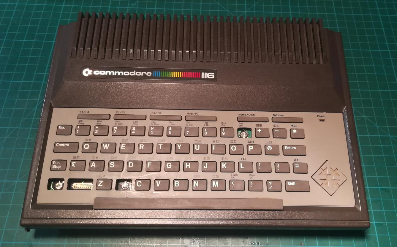
The case of an unrefurbishable(lolwurd) C116
Kaz who is the main person behind AtariOnline had shown a C116 during Last Party. He’d asked me if anything can be done to fix the missing rubber keys. I was like …

Fast forward a few weeks and String of Agenda (DemoScene group) bought that C116 from Kaz. He lives not so far away from me so one day he’d asked me if I could have a look at his C116 and maybe work on it a bit because OBVIOUSLY, it was dead, and also obviously I was like HELL YEAH.
Guys from Agenda create awesome demos as you can see on Pouet so I was like … of course, I will have a look at it and help out my fellow demosceners 😀
Inspection
Apart from missing keys, the machine didn’t look bad at first sight.
It took me a while to figure out how wrong I was 😀
A lot was broken in this Commodore but let me start from … the start? 😛
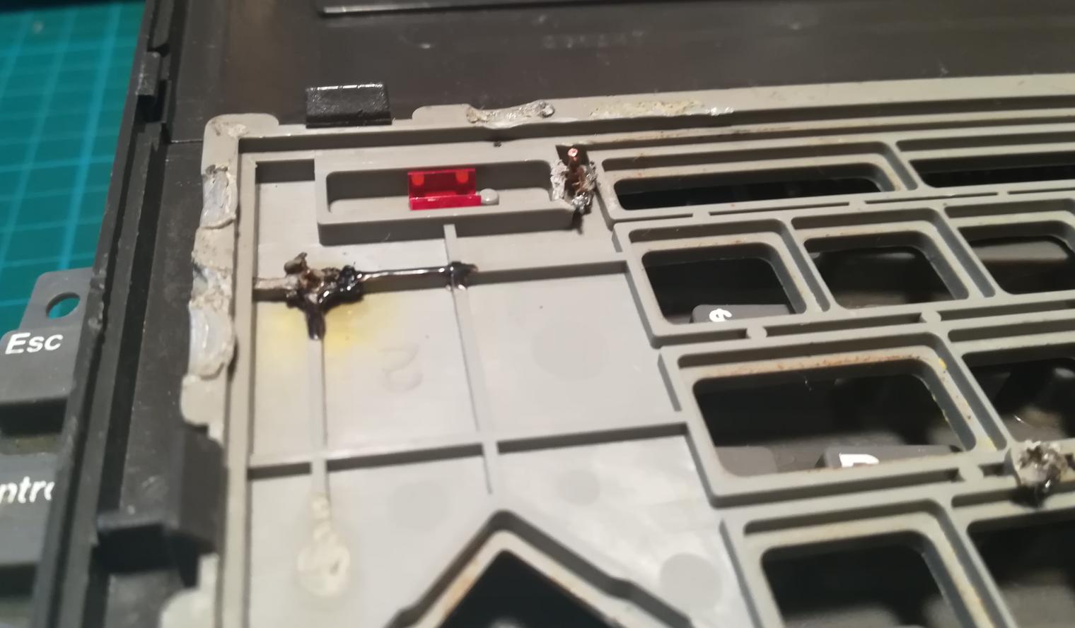
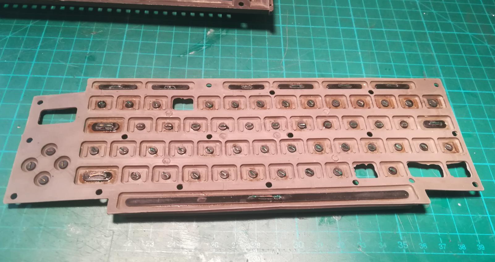
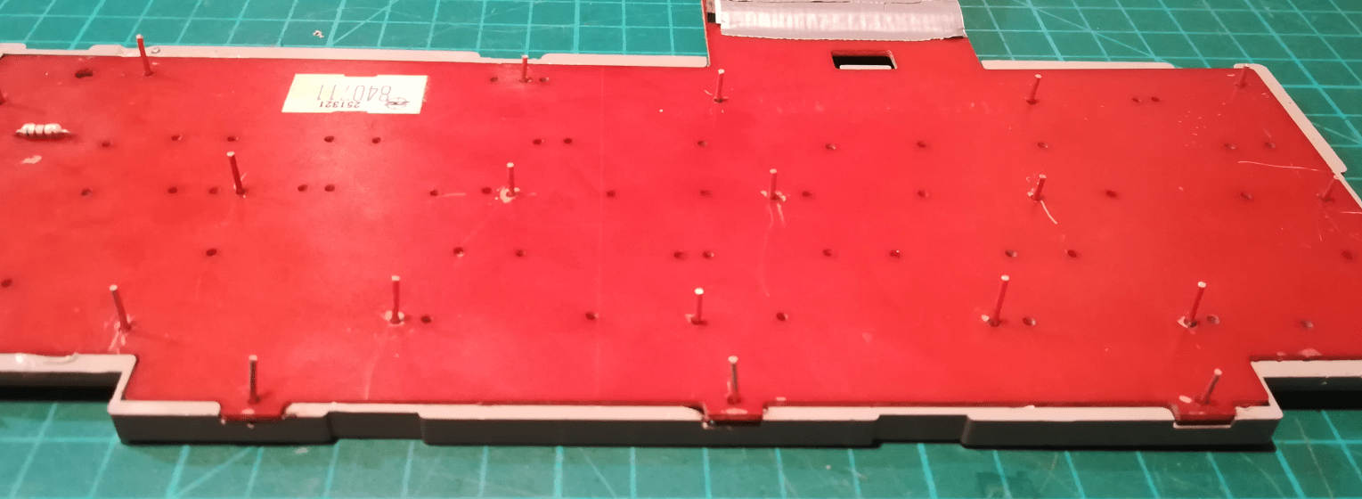
A keyboard PCB in a C116 is held by plastic poles that are melted after mounting. It is built as a piece that wasn’t meant to be ever disassembled. Someone figured out that metal wires can replace original design by simply melting ’em into a keyboard case. The idea itself was great but … the temperature used by the original modder was a bit too high resulting in a lot of charred plastic.

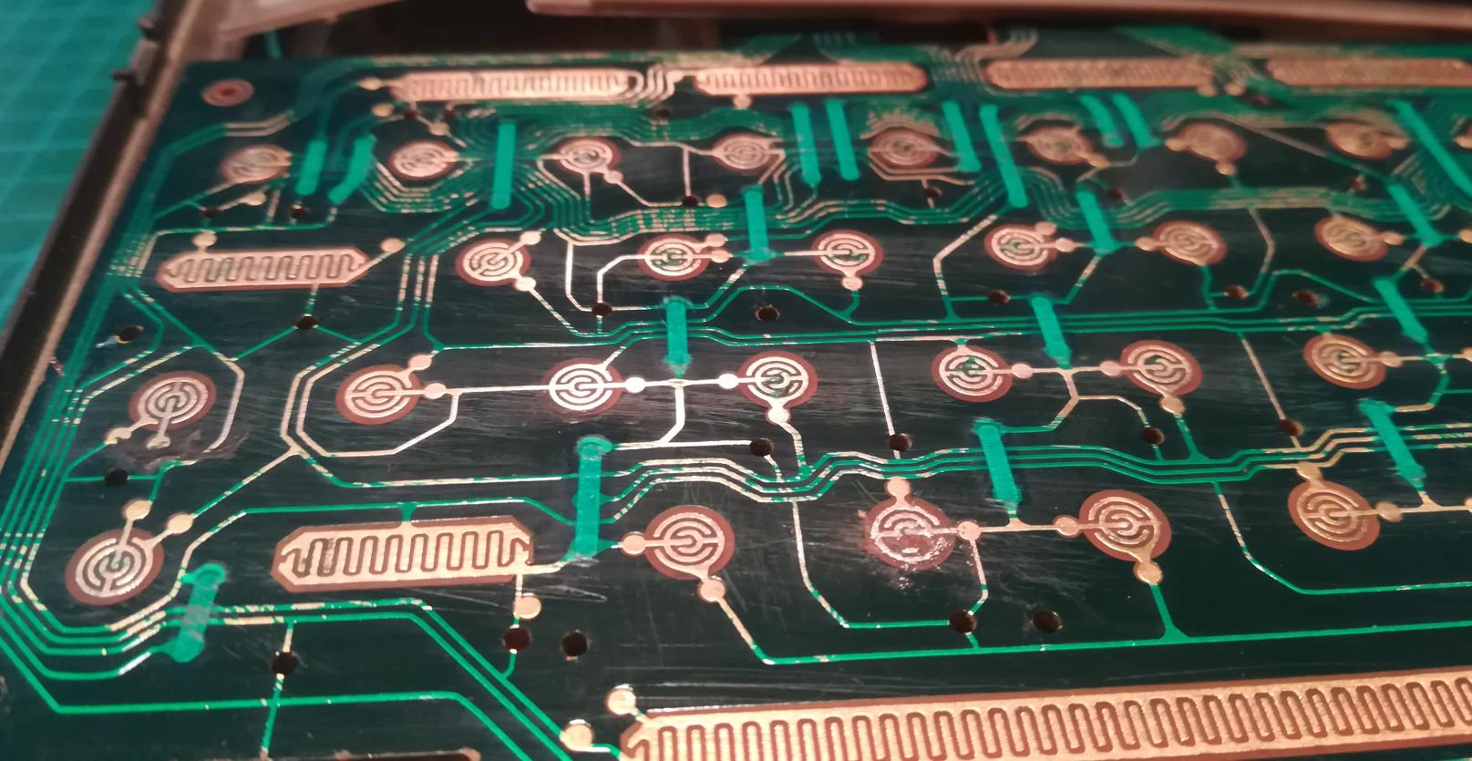
Sandpaper used to “clean” pads on a PCB was a bit too thick which resulted in scratches instead of polishing and introduced new problems but more on that later.
Another problem that I’ve found was an “upgrade” of graphite pads that was supposed to sort out contact problems.
Well, maybe it worked at the very beginning but stopped working with time. Here is why:
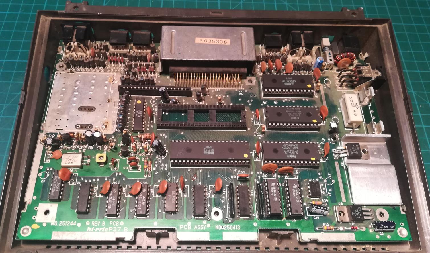
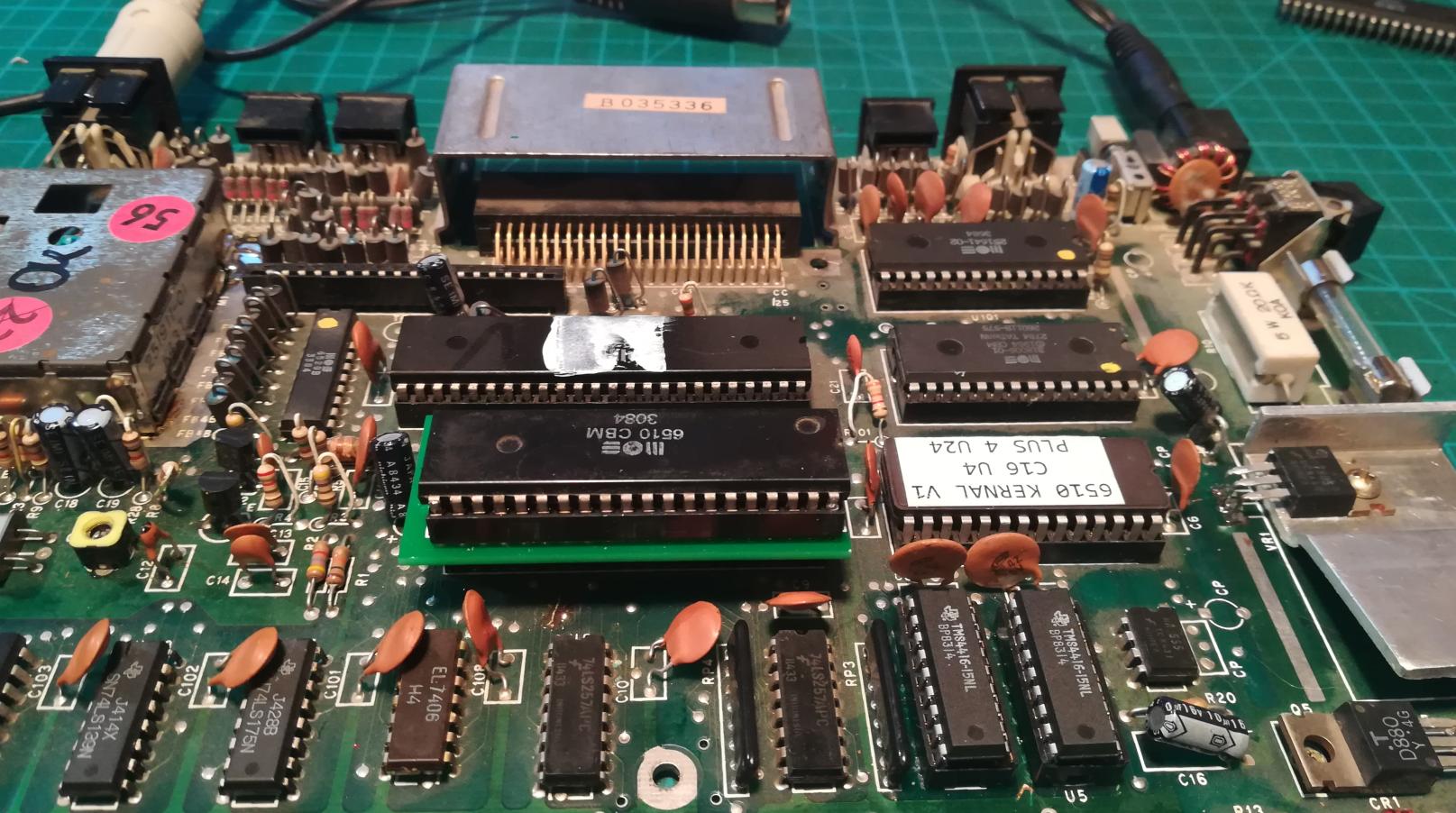
Mainboard
The unit itself was missing a TED chip. TED is responsible for a lot of things, like video output.
One of the traces near the CPU was looking a bit weird.

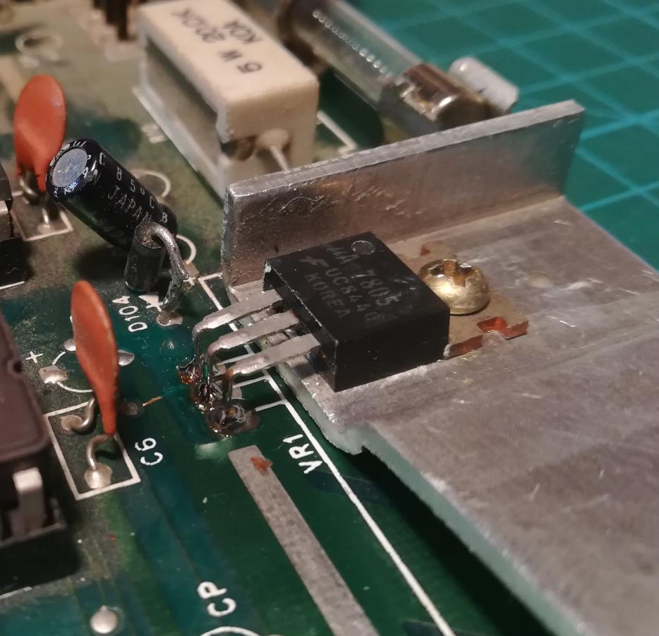
LM7805 voltage regulator had some issues sticking to a mobo and that was one of the first things that I repaired to check what is going on with this machine. Without supplied voltage, not much can be diagnosed, or can it? 😀
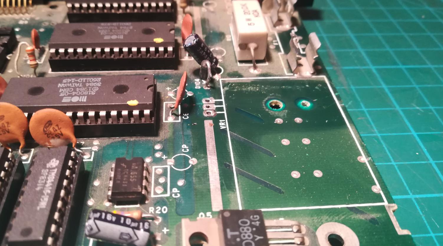
The RF modulator
But that is not all, there were more missing parts, like the RF modulator for example 😀
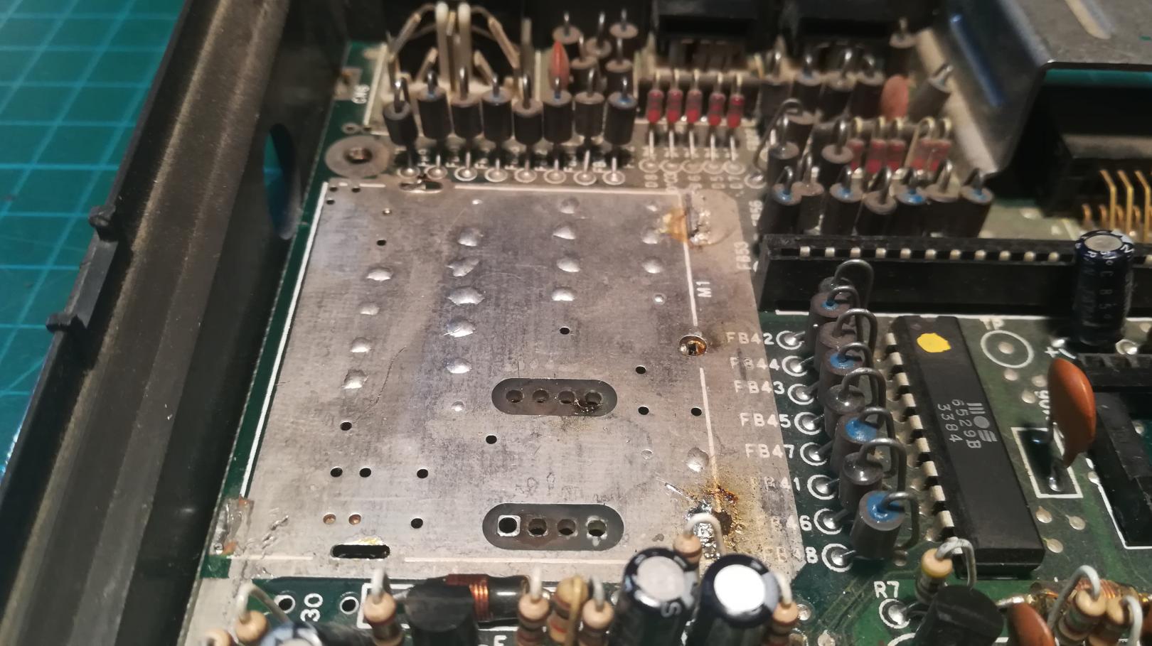
String told me that he’d desoldered some weird mod from this PCB near the RF modulator area so the next step was to fix traces and install the original modulator which I’ve borrowed from a dead C16 motherboard since it shares the very same design

Unfortunately, that didn’t help much – still black screen without any signal at all. However, after a while, I noticed it! Ahaaa!
Lemme show you:

Hard to spot and broken trace FTW! but it was easy to fix. Phew!

A quick test aaaaaaand …..
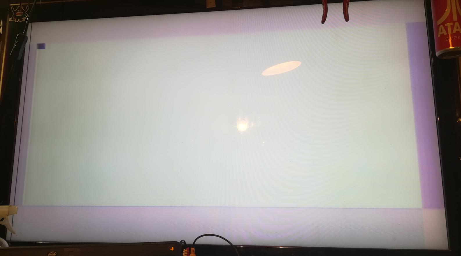
Booom, we’ve got a video! YaY!!
TED chip was tested in another machine so I was sure that it works, but I didn’t have a working CPU. Instead, I’ve installed a 6510 from Commodore 64 with an adapter and hacked ROM.
With a working CPU onboard, I’ve run it and got this.
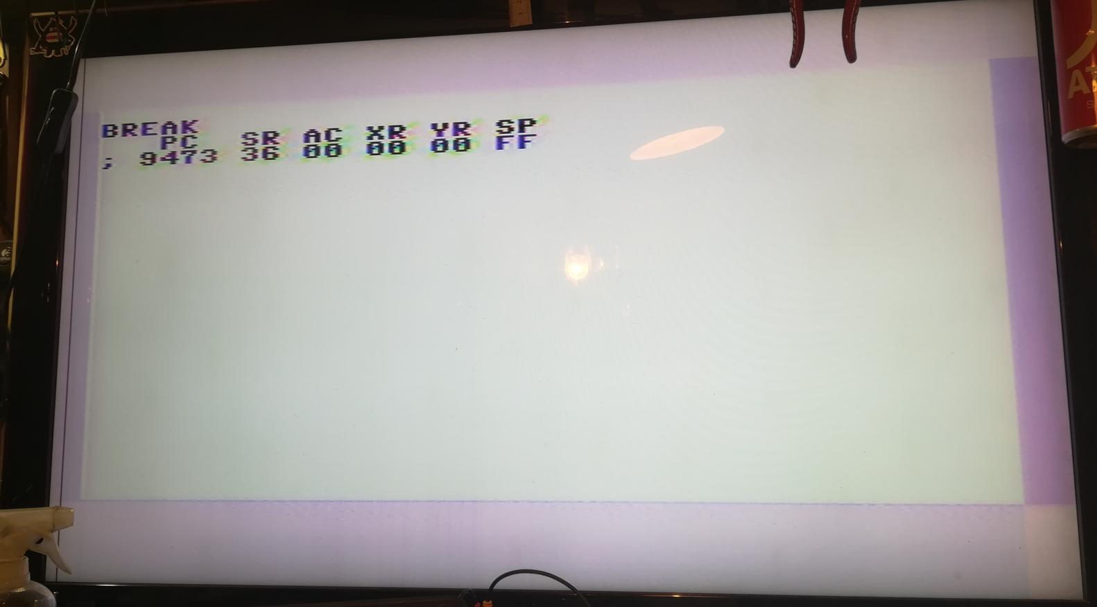
Commodore entered a monitor mode. That simply means that there is an issue with BASIC ROM. After flashing BASIC onto a brand new W27C512 flash chip I’ve finally got it working!


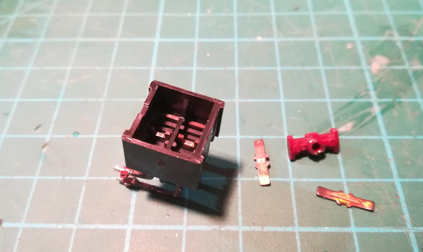
Unfortunately, the power switch stopped working. So I had to quickly disassemble it and clean all tarnished pins.
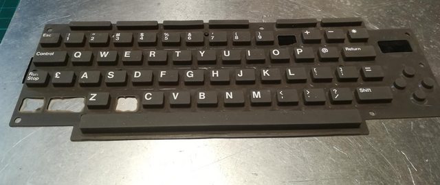
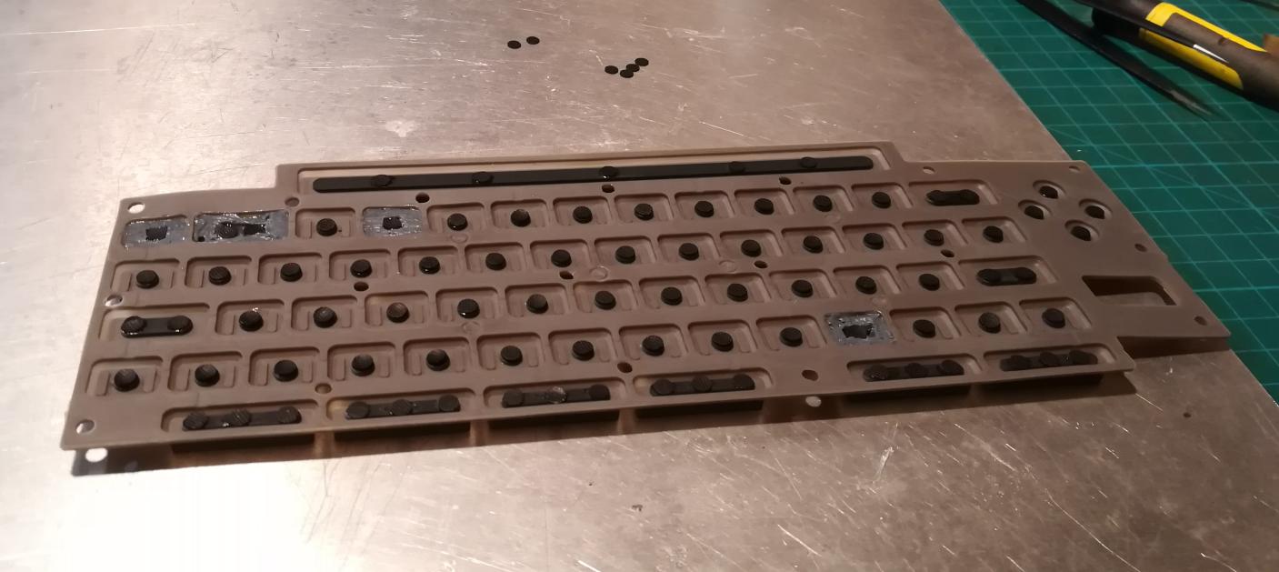
The keyboard
The major problem with the keyboard was that it was missing four rubber pads(one bigger and three smaller)
Someone simply has torn ’em out …
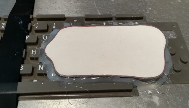
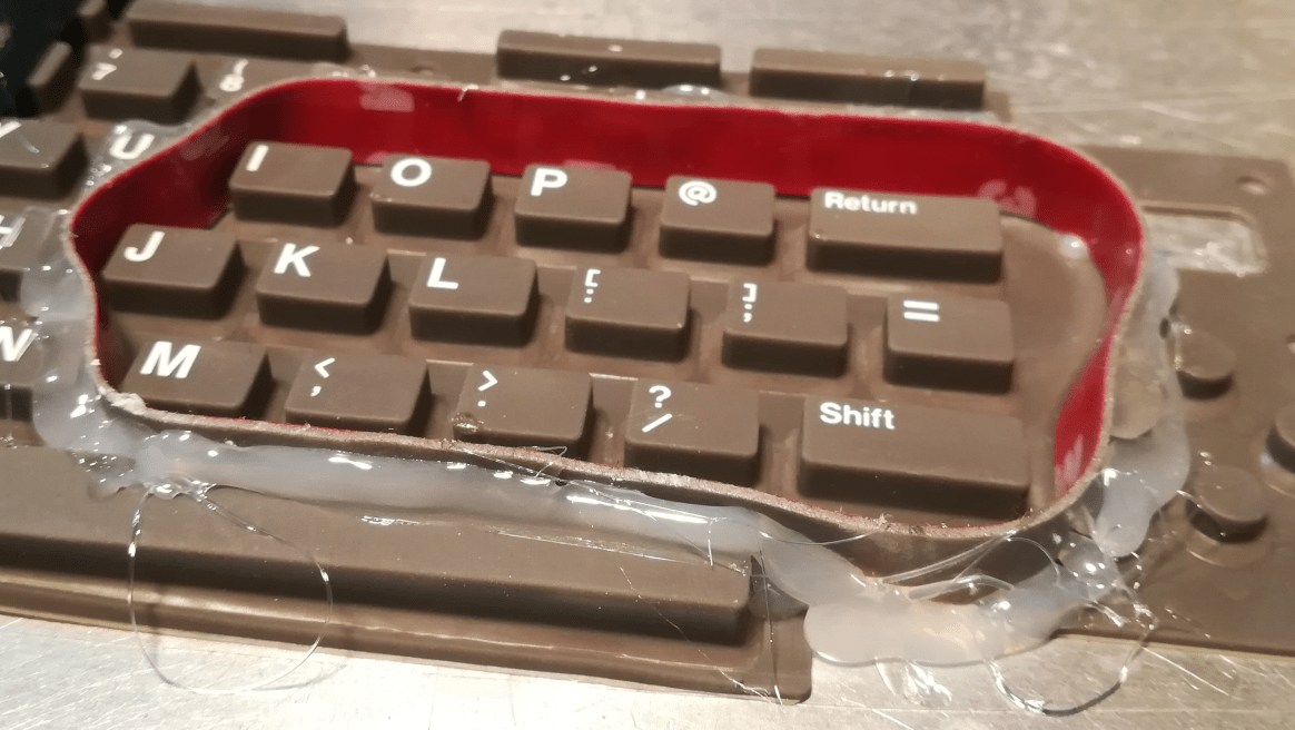
I had a cunning fixing plan on my mind but first I needed to create a mold.
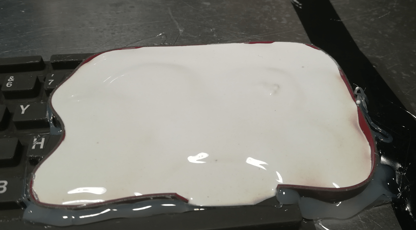
First, I had to cover the underside with a piece of electric tape.
An electric tape was chosen because it had a good adhesive and it stuck to a rubber nicely.

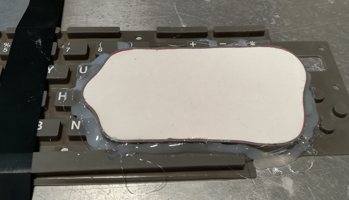
Next, I created a “barrier” from the foam tape and used hot glue to keep it in place. I’ve made it a large area to have more options in case of a poor mold.

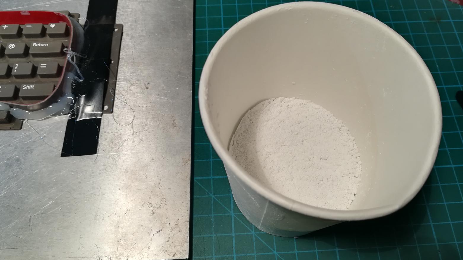
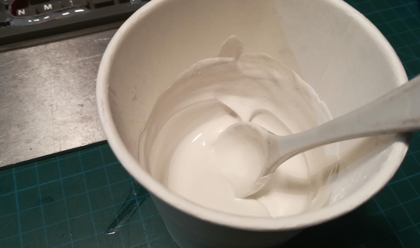
Plaster mixture preparations are in progress.
Molds
Pouring …
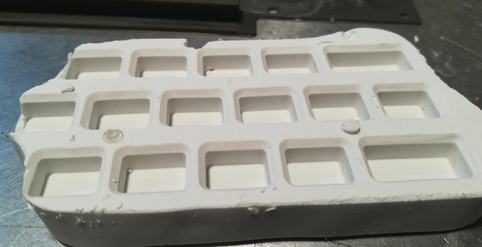
Solid and ready to extract.
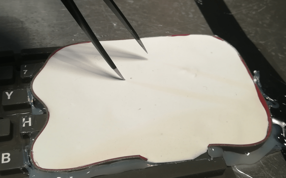
This is where it turned out to be a failure 😀

Apart from the obvious mistake with trapped air bubbles caused by the wrong pouring method, it also turned out that I didn’t clean rubber pads properly so all dirt was now perfectly transferred to a mold lol.
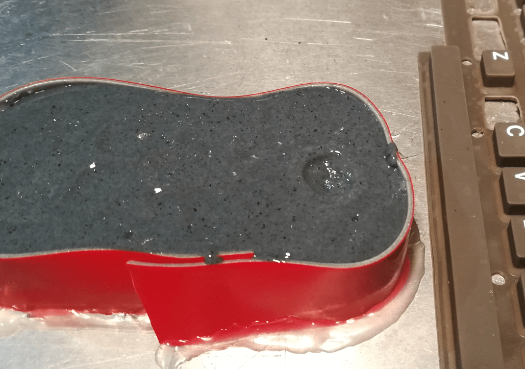
Take two

Now, a bit better 😉
With a nice and clean negative mold, I could move on to another phase.
This time, I’ve hot glued a mold to a metal plate.
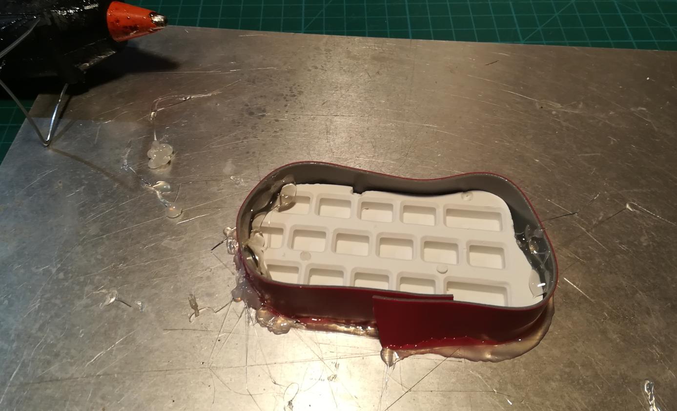
I ordered a dark grey dye a week before but a quick test revealed it wasn’t dark at all and didn’t match the original color 🙁

Silicone molds
I had to improvise and darken it quickly because at this stage I already had a molding silicone mixed.
Barbecue charcoal to the rescue! lol!
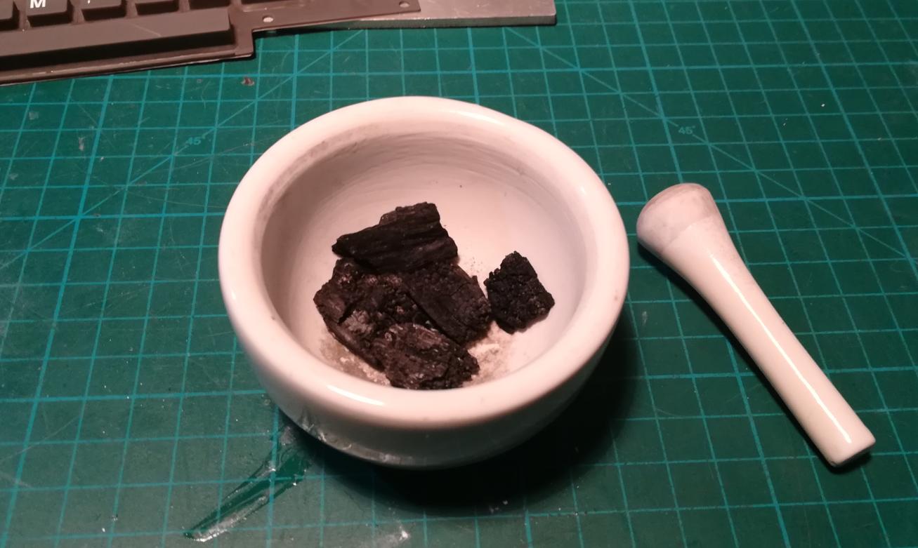
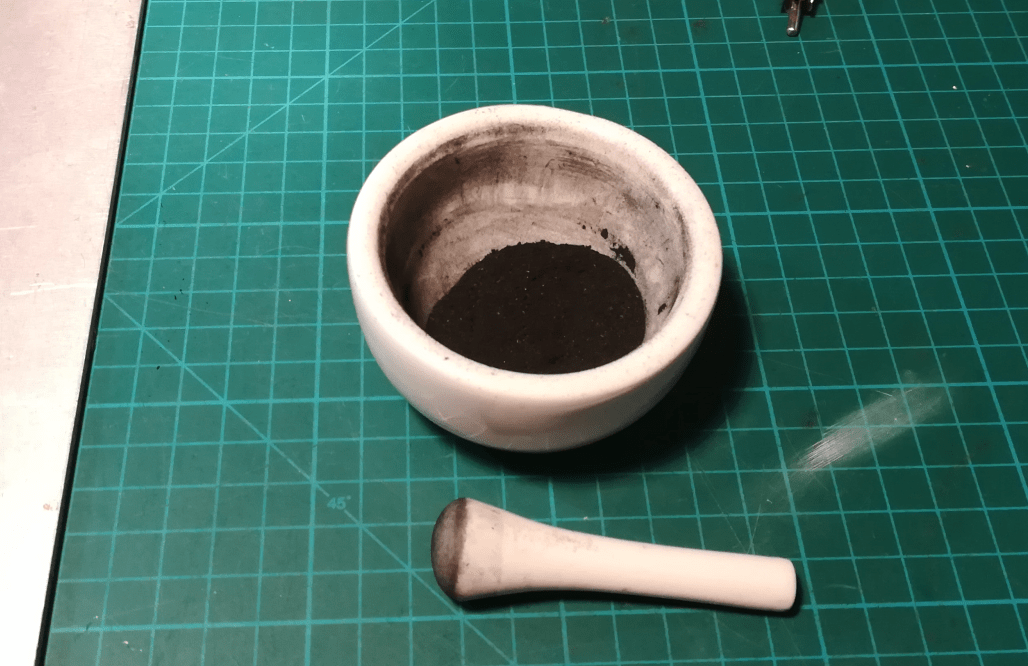
I was hoping that it will match the original color but hmmm it didn’t 🙁

I’ve tried to add a bit of Fluorescein but it didn’t help at all.
Lesson learned, Fluorescein won’t mix with molding silicone.
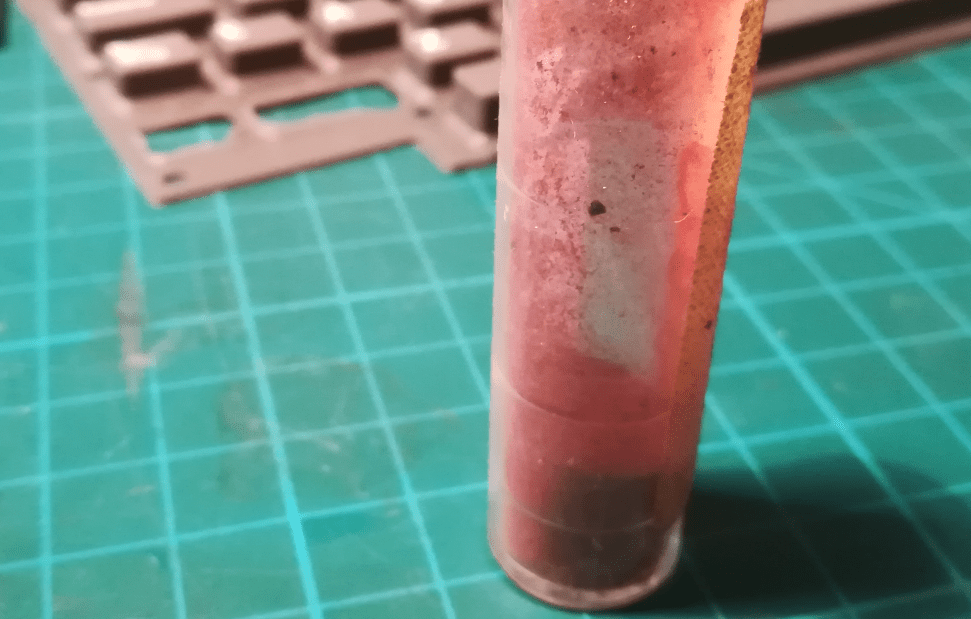
Anyway, I’ve decided to continue.
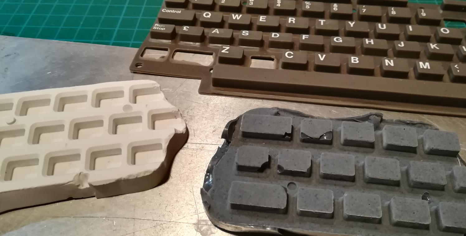
Replacements
After the silicone is cured Is could remove it from the mold, cut some new keypads and put ’em in place 🙂


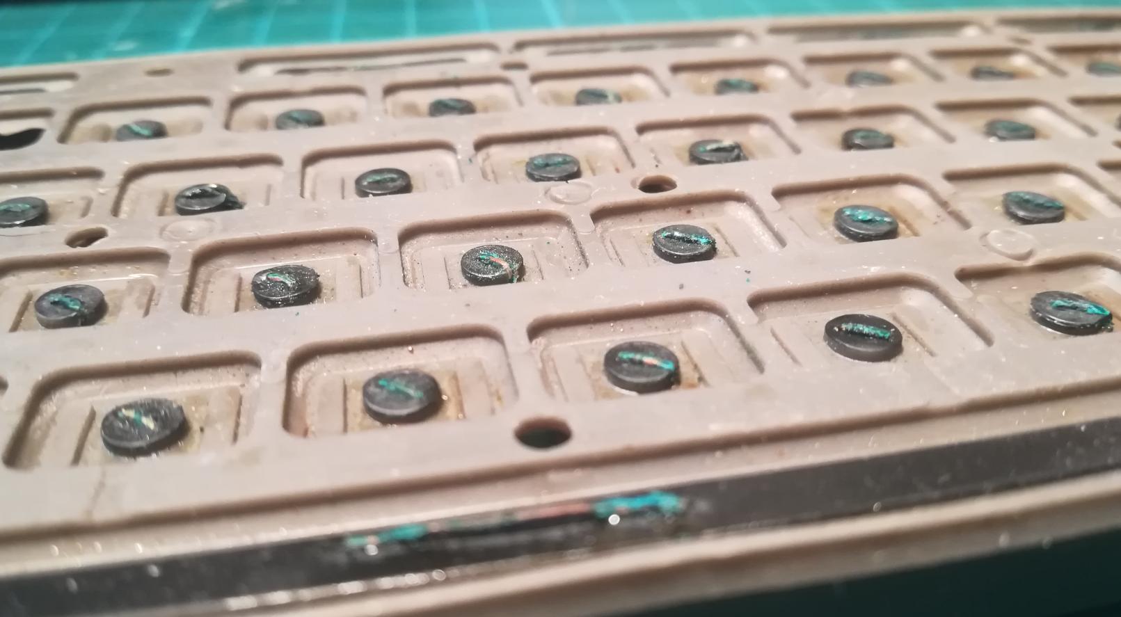
Graphite pads
So I’ve run some tests with these new keypads armed with conductive rubber and it turned out it worked OK, but to my surprise, the original pads didn’t work at all … at least the majority of keys didn’t work.
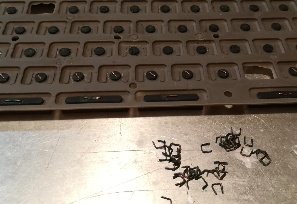
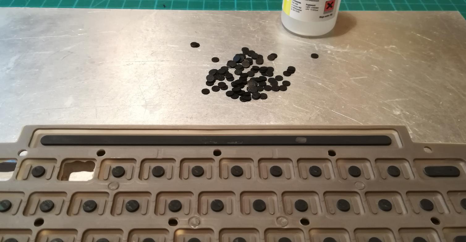
U-bent copper wires were nicely corroded and were covered with copper oxide(black color).
I planned to remove U-bent wires and glue on brand new conductive pads that were bought as a replacement for the TV remote 🙂

Using CyanoAcrylate glue to bind conductive pads with the original rubber turned out to be a mistake. Pads just didn’t want to stick to the original rubbery surface.
I had to redo the whole thing, but this time I’ve used silicone.

Finally, I’ve made it 🙂
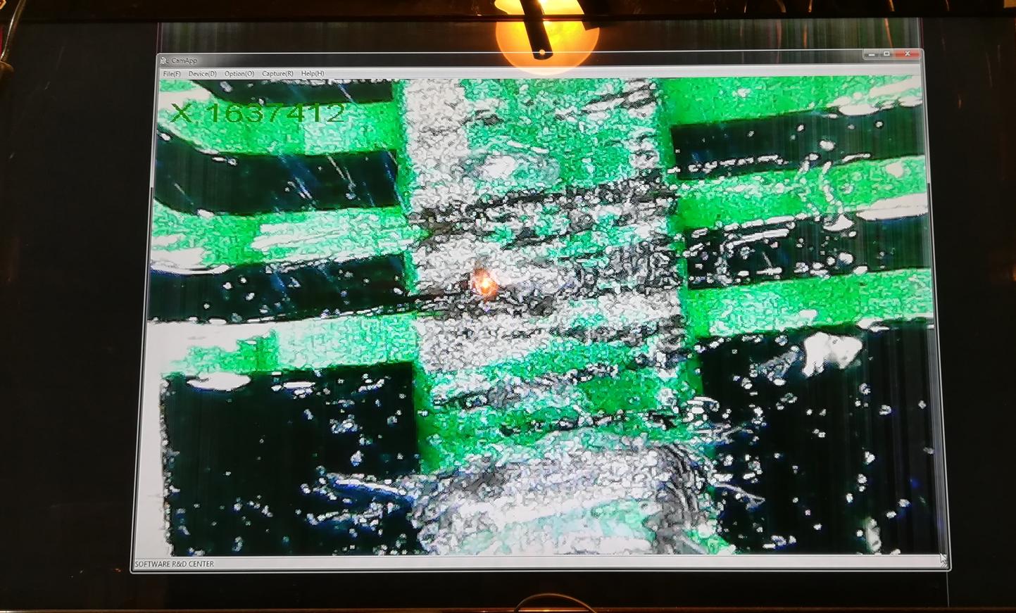
KB PCB
Then, I could focus on a keyboard PCB.
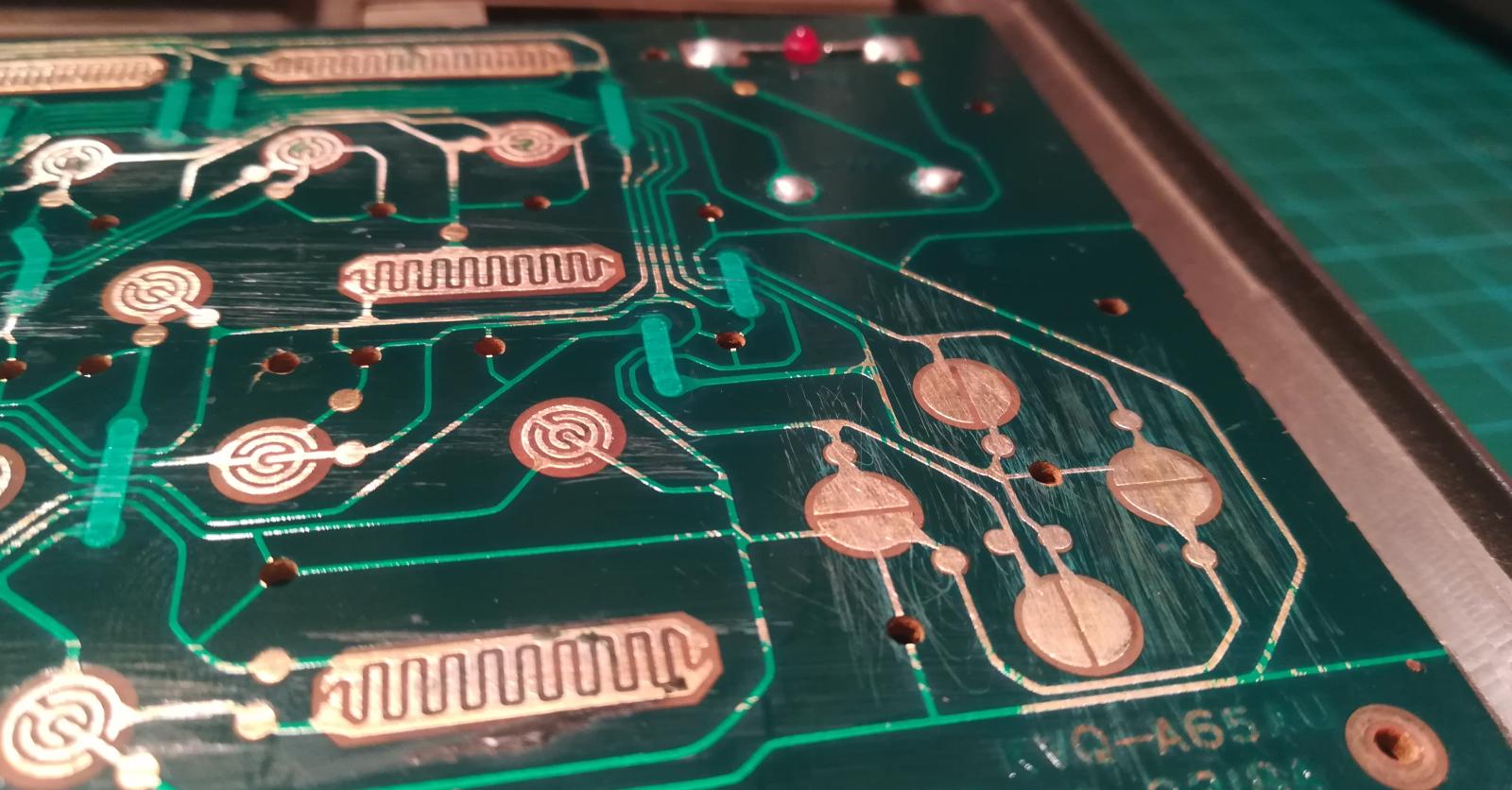
It looked like someone used the wrong sandpaper grit because it was heavily scratched. I’ve used 2000-grit sandpaper to smoothen it a bit.
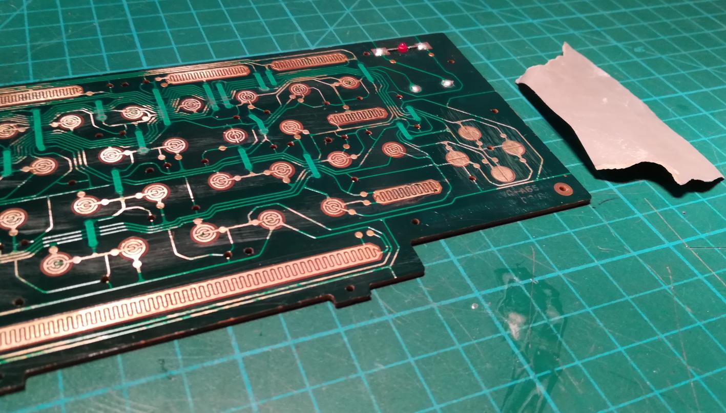

After sanding it, I coated non-conductive areas with a PVB varnish.

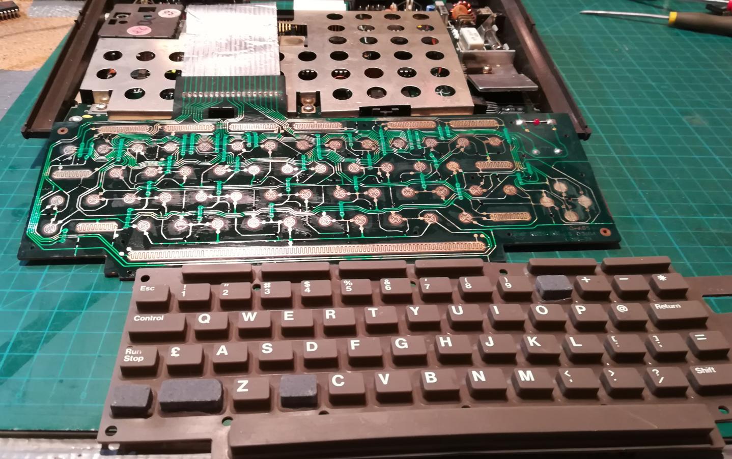
Keyboard story continues
If you think that was it then you are seriously wrong lol.
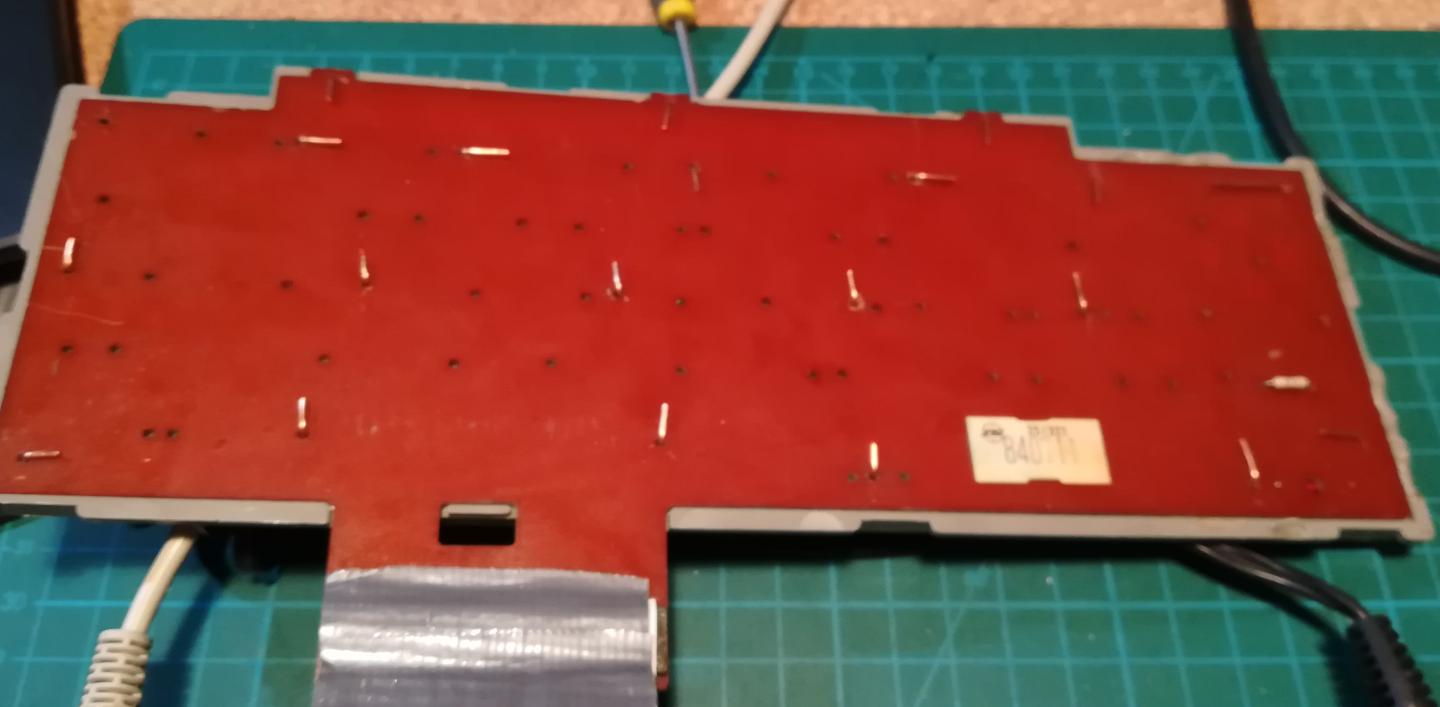
My test setup below revealed that a lot of keys didn’t work at all.
Some columns didn’t work and it looked like some address lines are broken.
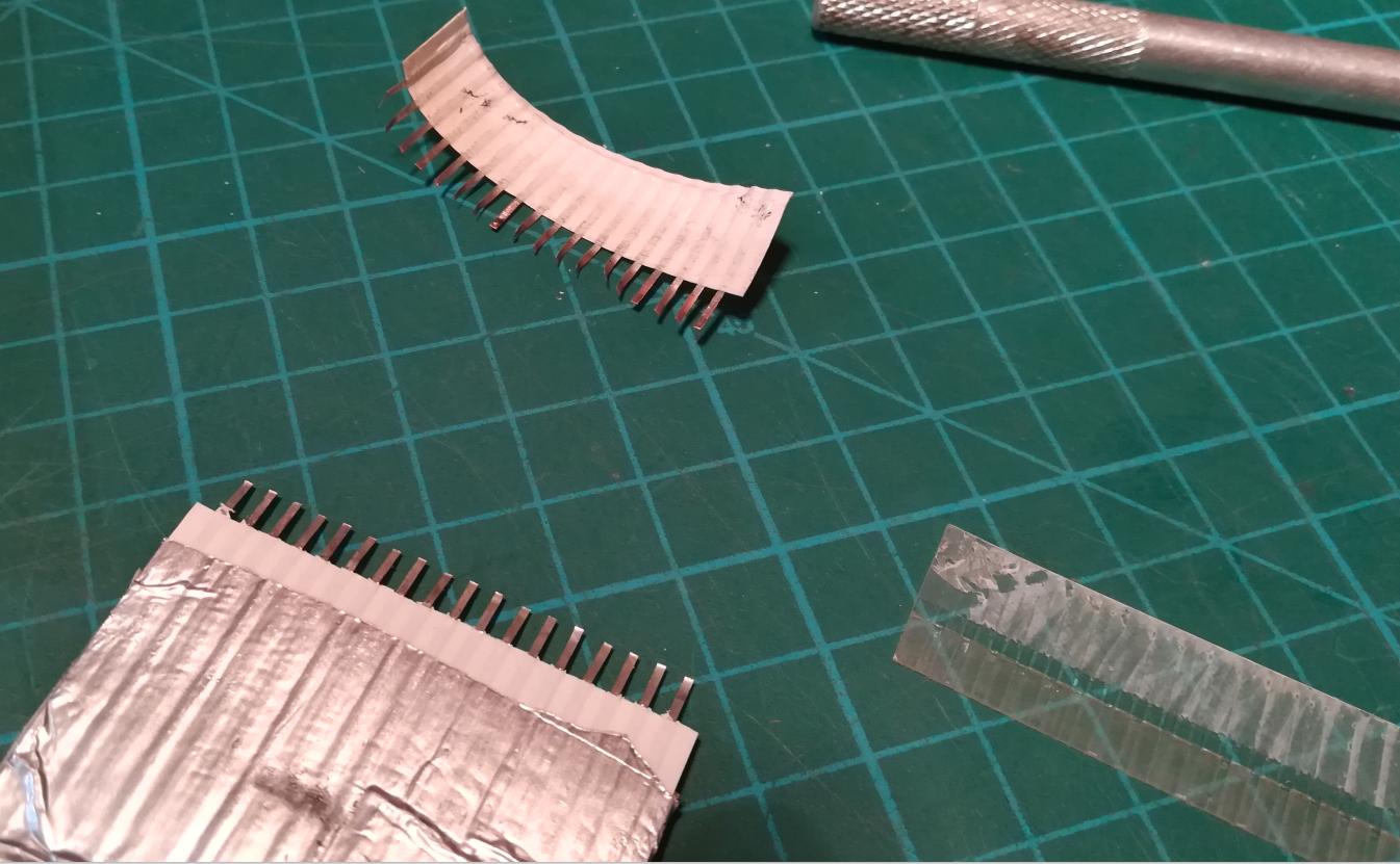
To investigate it, I’ve started to check the continuity between the keyboard PCB and the end of the connector membrane.

Bingo! broken trace was found again!

That was fixed by soldering a small wire over a trace.

… but still, some keys didn’t work …
I was like …

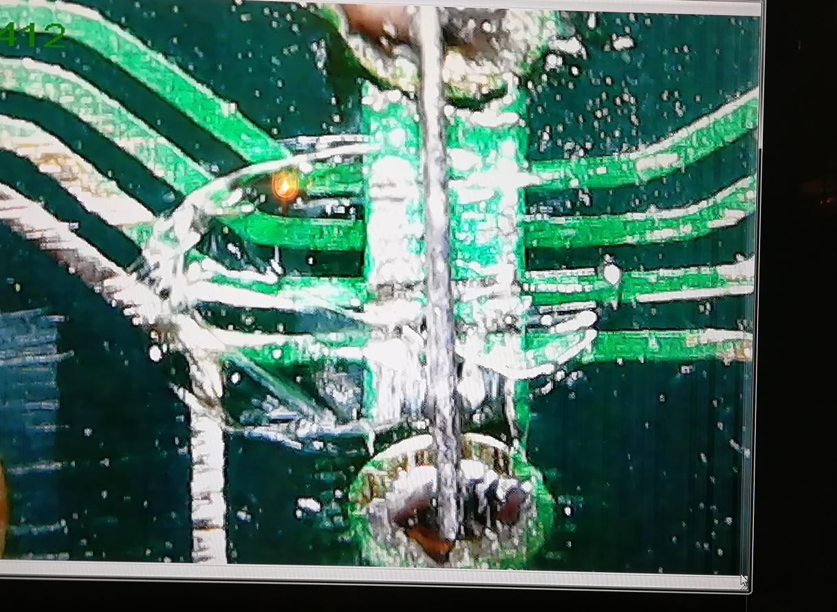
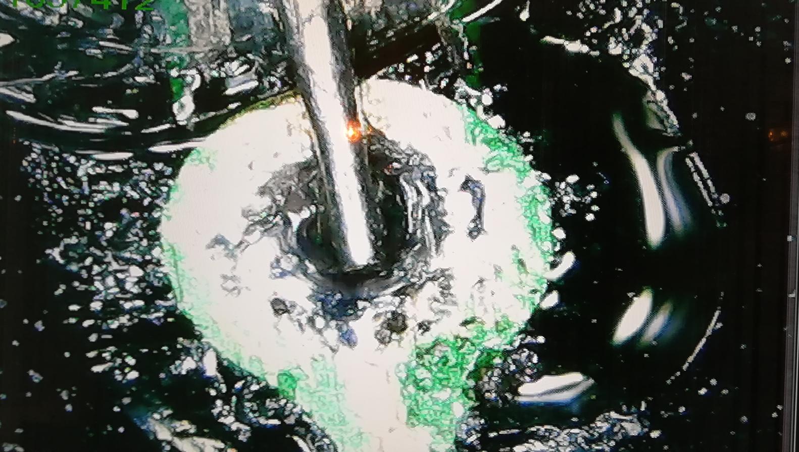
I’ve managed to narrow a problem to a few keys. Damage made by wrongly chosen sandpaper was a direct cause of it. A guy who tried to sand it before me simply destroyed some traces on a PCB and I didn’t notice it at first.
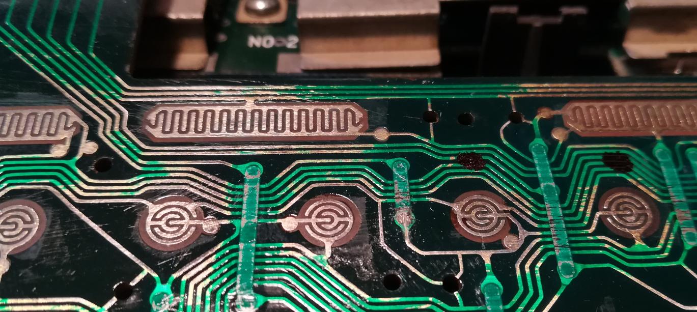
WARNING! CRAPPY CLOSEUPS ARE INCOMING! 🙂
I’ve interconnected damaged traces with a Kynar wire.
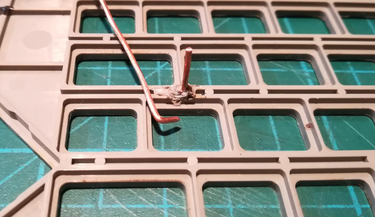
Plastic chassis
With traces fixed, I’ve started to work on copper wire hooks that replace original plastic poles.
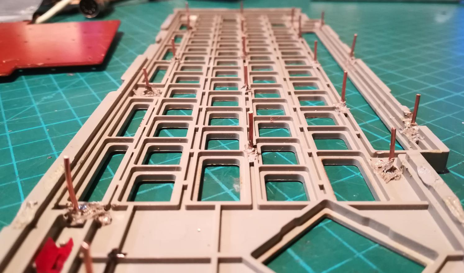
I’ve assembled a keyboard and run some tests again but unfortunately, some keys stopped working again so still that is not the end of this mess yet 😀
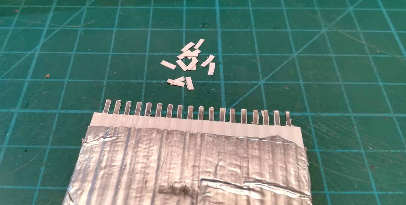
The connector was a problem again.
I’ve decided that I’ll cut it and redo the connector from scratch.

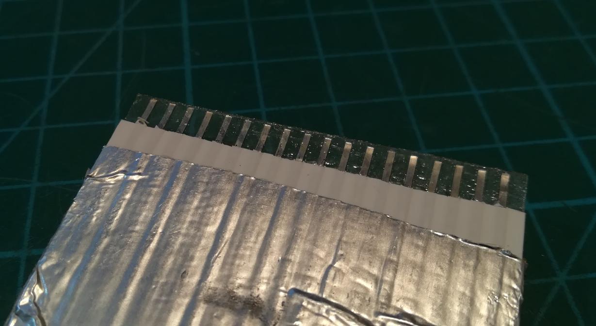
Finally, the whole keyboard started to work! Phew! 😀

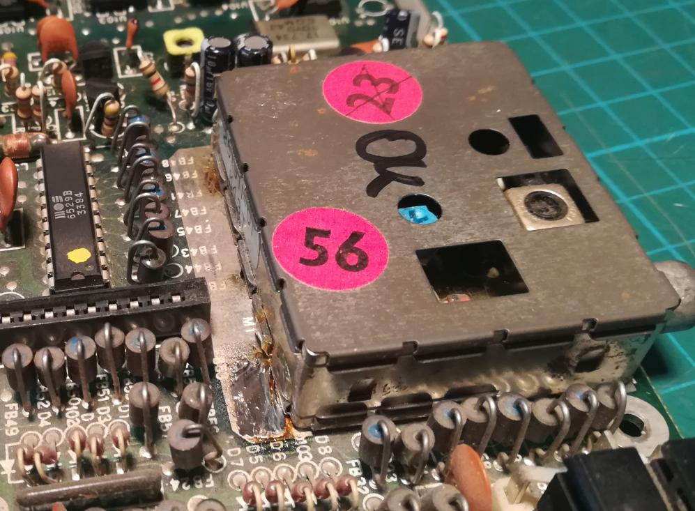
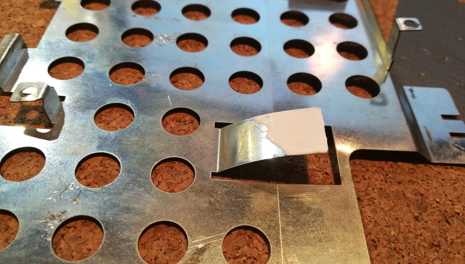
The only thing left to be done before assembling C116 was to put some thermal paste onto a shield that also serves as a heatsink.
Final thoughts
It wasn’t the greatest job ever. I will have to work more on my knowledge of various coloring agents and pigments. However, In general, I am happy that another machine is working again 🙂


OUTRO
If you want to get retro gear or hardware modules, please visit our shop
New products are added every month.
Also, please support our work by spreading info about it.
Without your support, we simply cannot grow and we have a lot of new excellent retro hardware (and more) products to come 
Could you tell to us which SILICONE was used
for molding exact name of product
thank you…
Oh, I would love to, but I just don’t remember as it was a few years ago. However, it was a typical hobbyist molding silicone.
Can I ask, how did you attach the keys to the keyboard?
Oh, the rubber keys are thicker on the bottom and this prevents ’em from flying out.
Amazing! What a great job.
Thank you 🙂