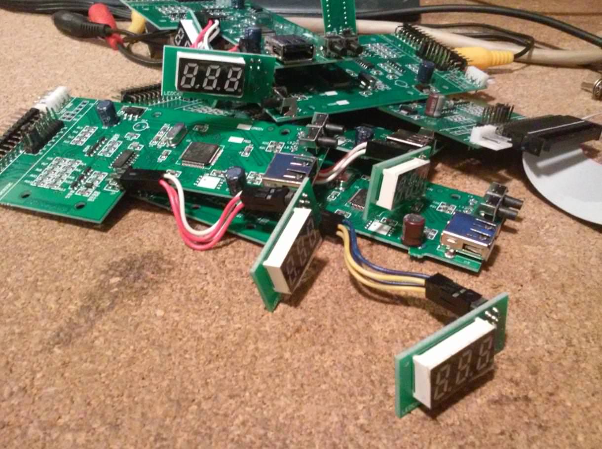
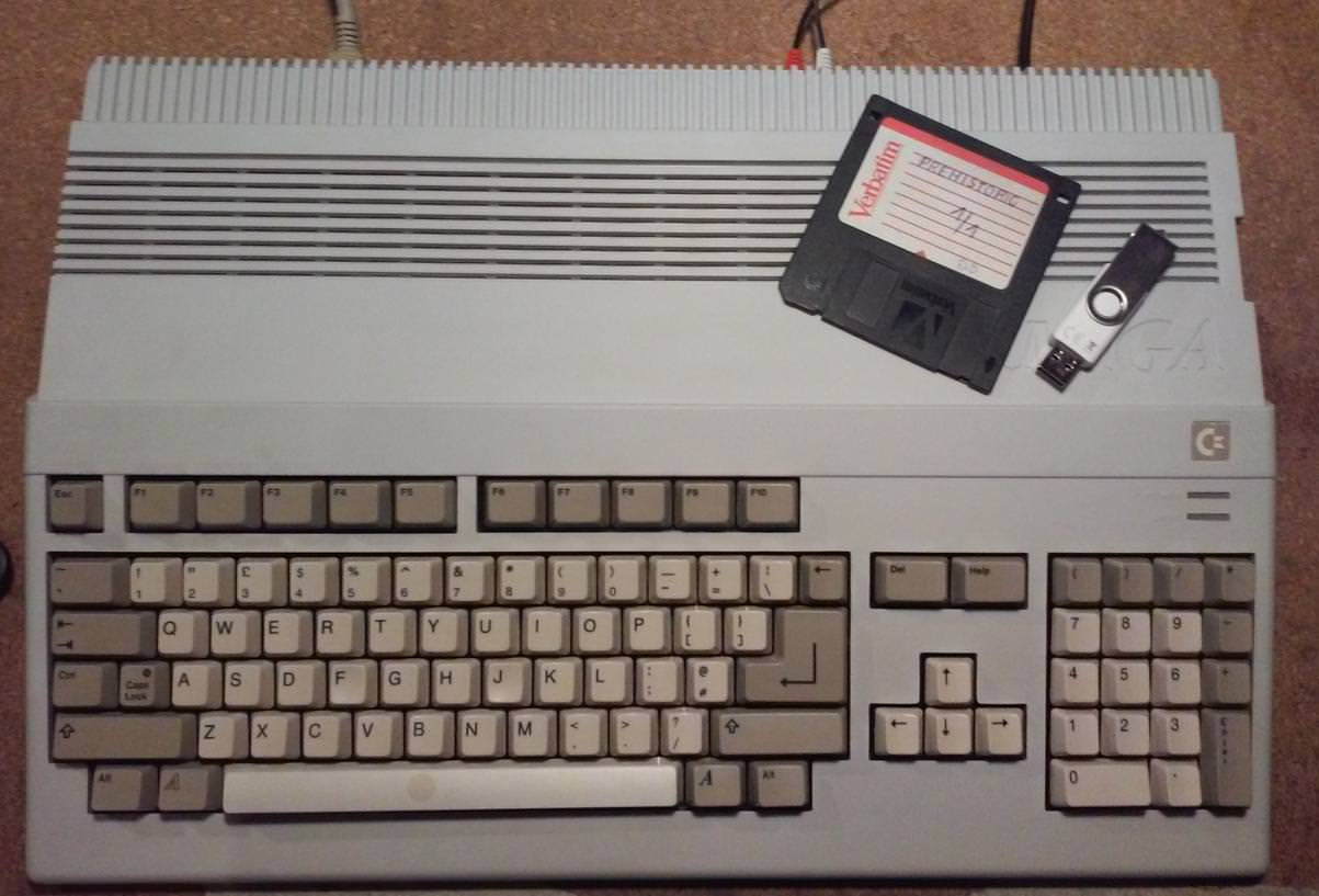
… or Amigaaaaaaaahhhh !

Yup, the above photo should be enough for a whole post but I decided that I’ll add just a bit more 😉
Mods
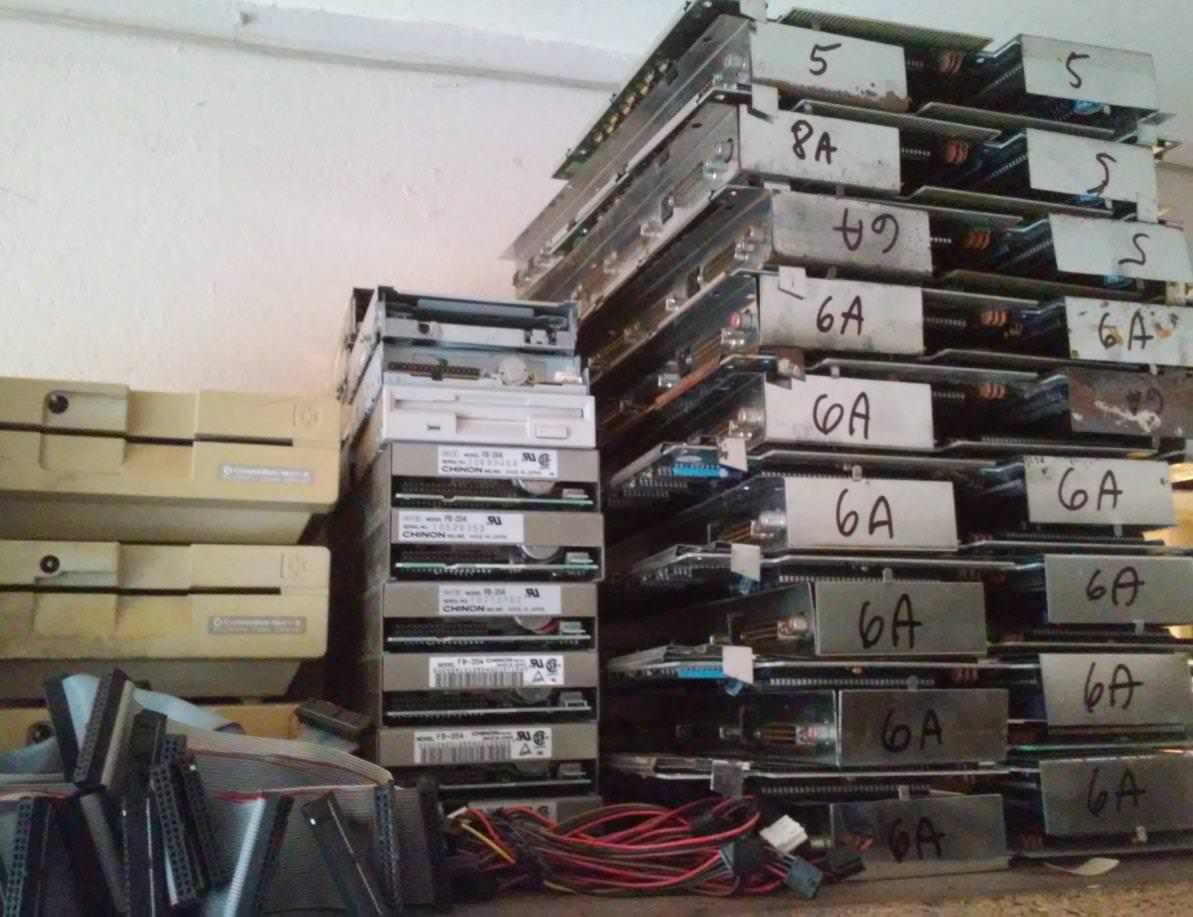
I am a happy owner of quite a few A500s in pretty crappy shape. I’ve finally managed to start some serious work with modding ’em.
I won’t post single-machine mods but rather a several mods in a few Amigas that I’ve pimped.
As usual, I’ve started with simple things 🙂
Disassembly and sorting.

Keyboards cleaning and whitening.
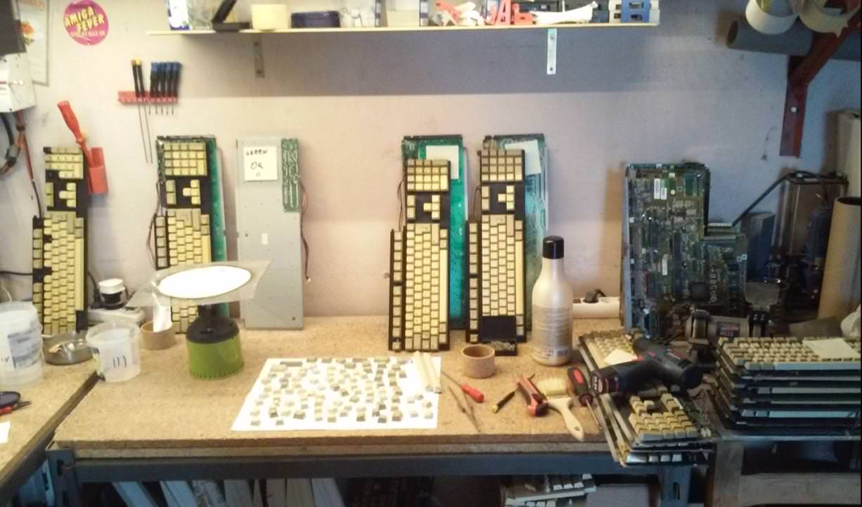
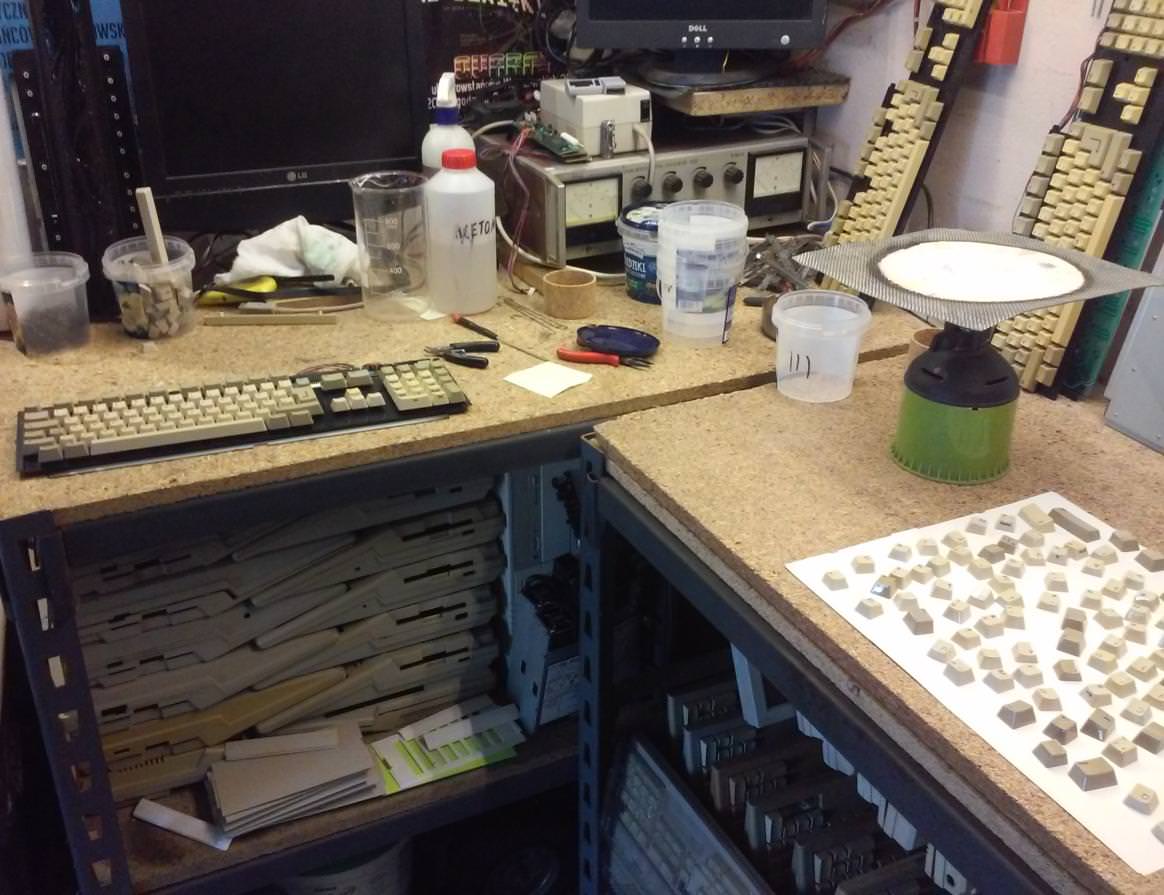
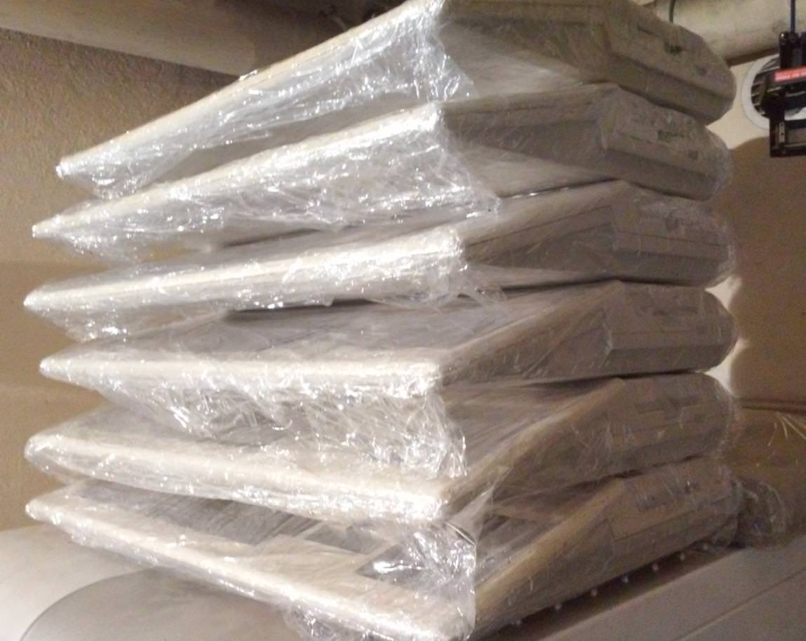
Cases whitening in progress.
1MB CHIP RAM Upgrade
Next on my list (I’ve skipped standard repairs) was to upgrade CHIP RAM on motherboards and make it switchable – trap door expansion enabled/disabled. However, It turned out that I have quite a few different mobo revisions in disassembled Amigas – 3, 5, 6A, and 8A.
I’ve decided that revisions 3 and 5 will be repaired, refurbished, cleaned, and left in their original form.
6A and 8A revisions are far better for modding, plus has unpopulated vias waiting for RAM chips 🙂
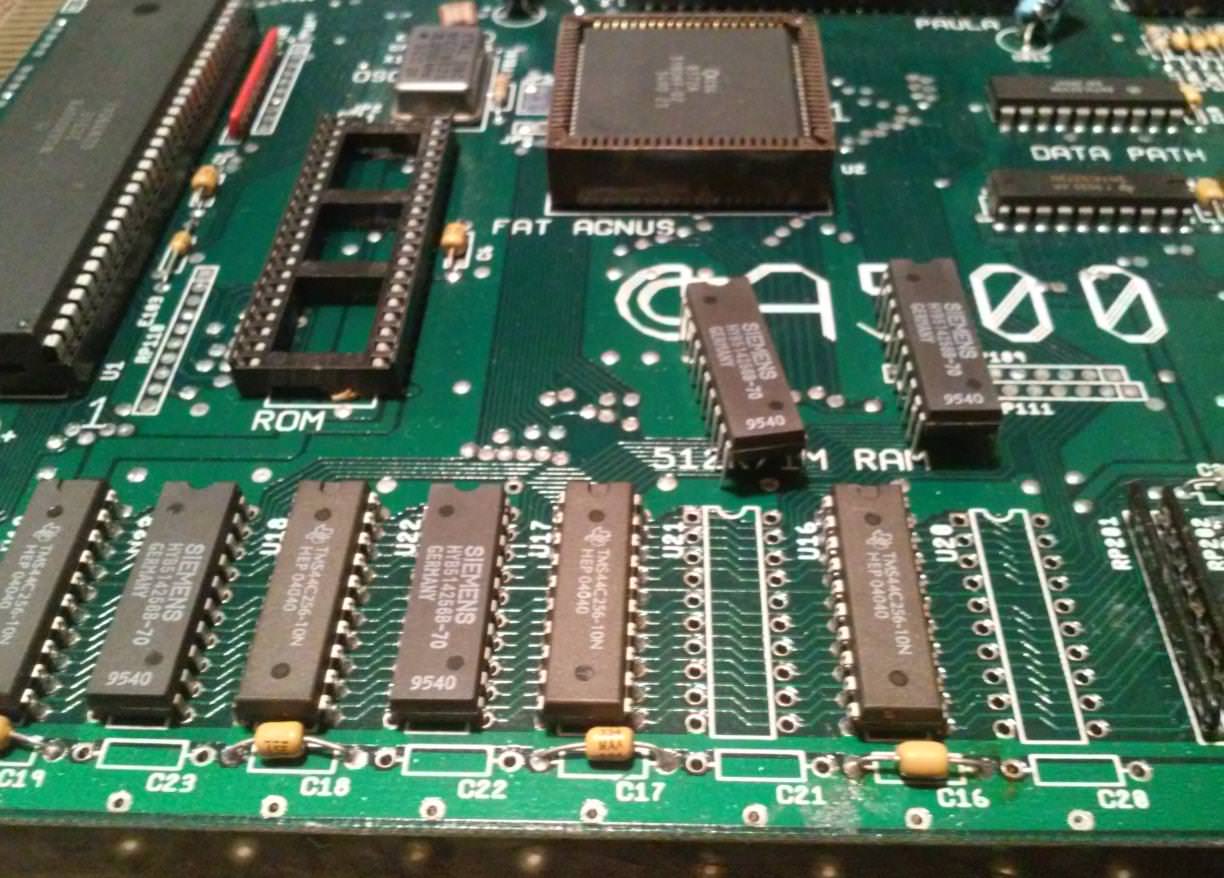
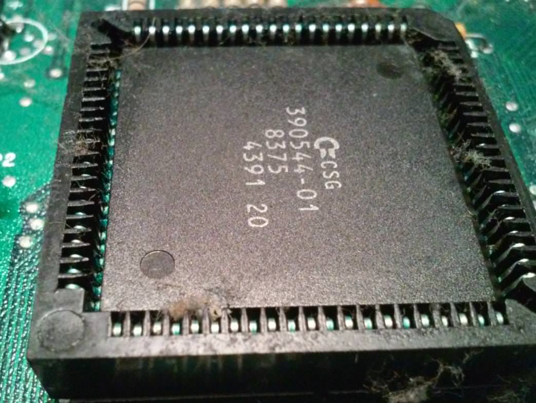
I’ve decided that I’ll go with a standard 1MB upgrade. Yes, I know that 2 megs are easy to do on rev. 8A or 6A motherboards with Super Fat Agnus(8375) but I just don’t have that many spare 8375s.
As I wrote, this upgrade has to be switchable. I wanted to achieve two options. The first, where I would have 1 MB of CHIP RAM available but with trapdoor expansion port disabled and a second option, 512 KiB of CHIP RAM available and trapdoor expansion ready to accept another 512 KiB of RAM. This is necessary because some stubborn programs (hardcoded memory regions) simply won’t run without expansion port RAM.
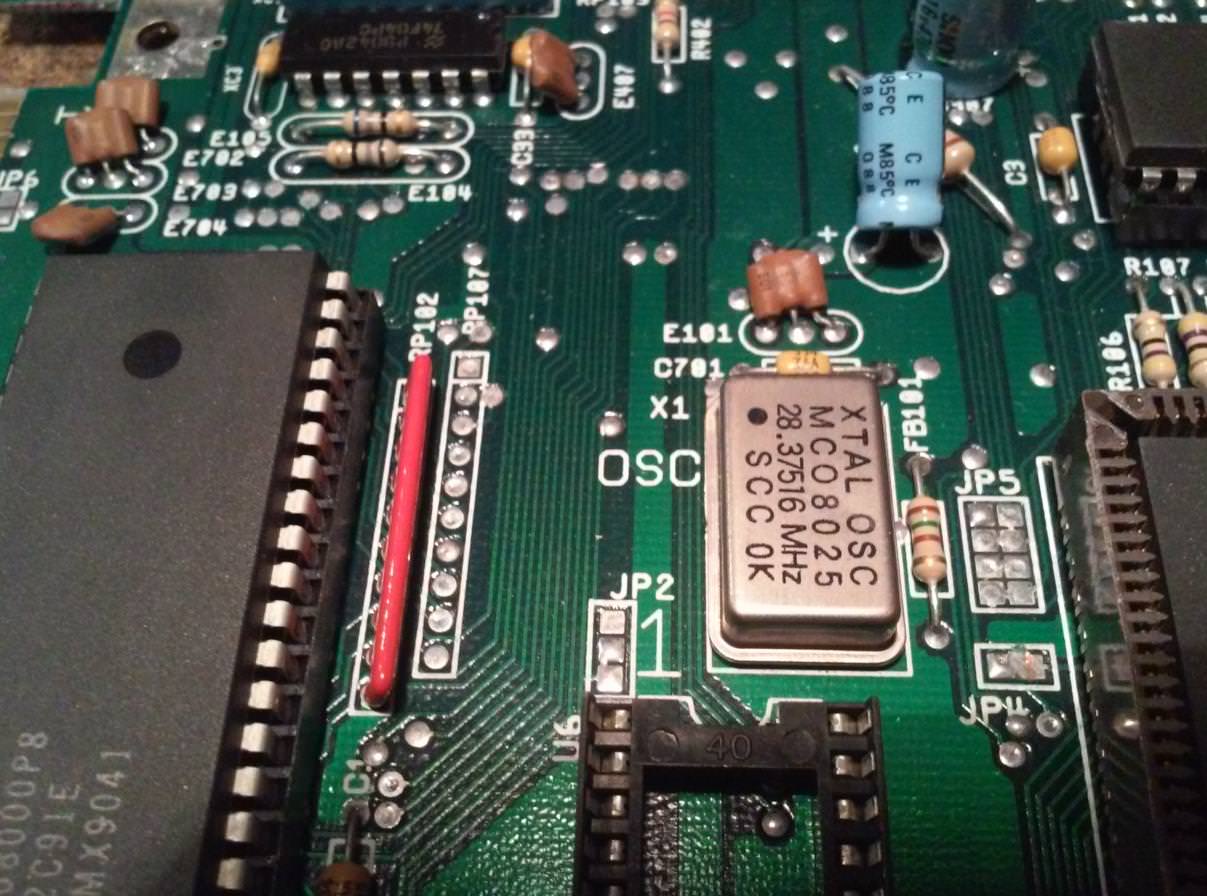
To achieve such mod in a 6A mobo, two jumper pads (JP2 and JP7A) have to be connected to a dual 3-way-switch. The first jumper pad (JP2) is located between the Agnus PLCC socket and CPU socket. It enables/disables more than 512KiB of onboard CHIP RAM.
The second jumper pad (JP7A) is located near the expansion port and it is simply responsible for turning on and off the expansion port.

Both jumper pads have bridges by default and both bridges have to be cut/desoldered.
Jumper JP2 has three pads and all of ’em have to be connected to a 3-way-switch.
JP7A only requires two wires instead of three and these go to the second section of the 3-way-switch.
In a rev. 8A motherboard, this is a bit more complicated.
There are three jumper pads involved – JP2, JP7A, and JP3.
JP2 and JP7A are configured the same as in rev. 6A.

The easiest way to describe the changes needed is:
JP3 has four pads that are by default connected like this -> “||”. This has to be changed to the following config -> “=”
Pics made before cleaning of course 😉


GURU MEDITATION?
I began testing this mod and started to get various, random GURU MEDITATIONS. Internet says that it is just a matter of re-seating a FAT AGNUS chip.
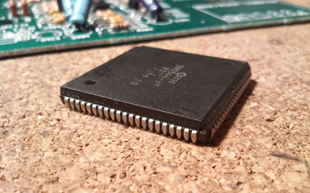
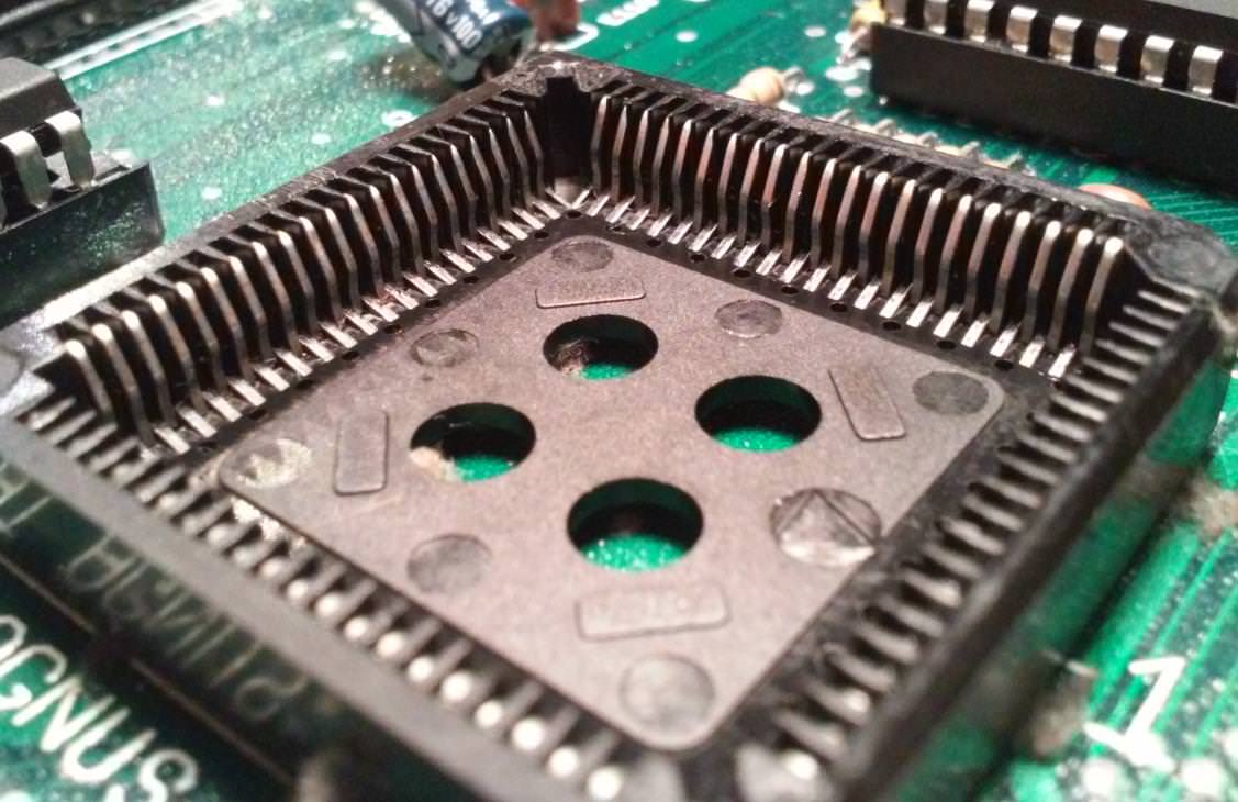
It is the only chip in a PLCC socket.
After several tests, I figured that it is simply not enough.
Five out of six times cleaning was needed as well but that still didn’t help much and I was still getting random crashes.

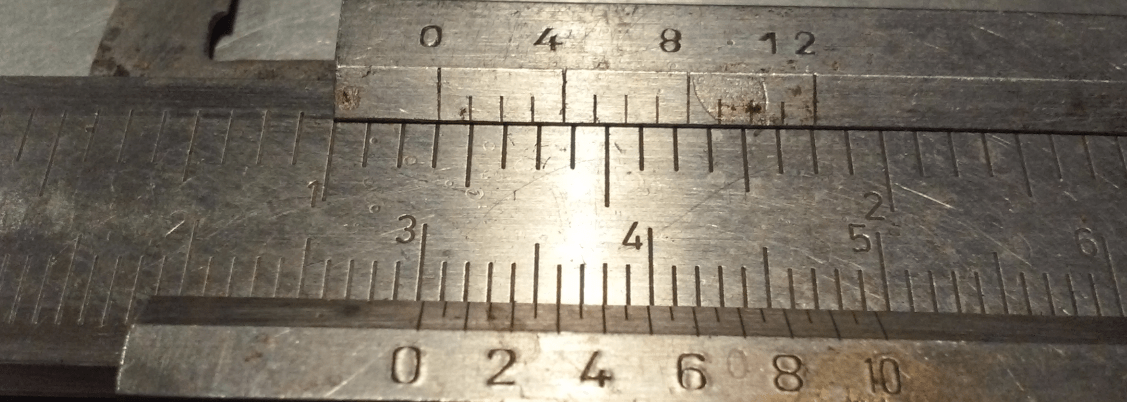
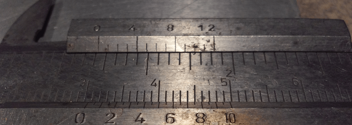
The simple measurement revealed that the chip is 30.3 mm wide (including pins)

I’ve tried to squeeze pins with a clamp but that yielded poor results – 30.35 mm
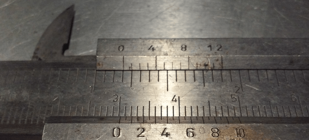
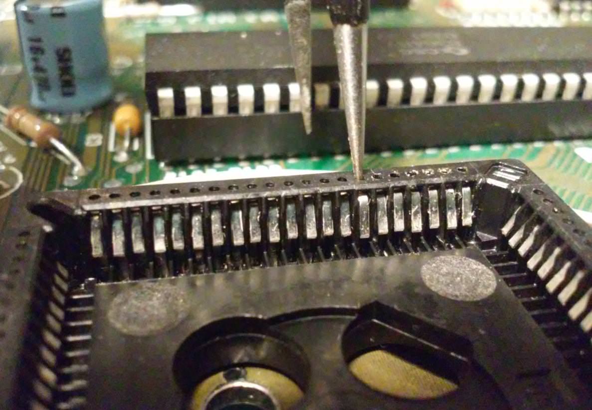
I’ve ended up moving each pin individually with a small screwdriver.
Mid-work photo so you can see a difference.
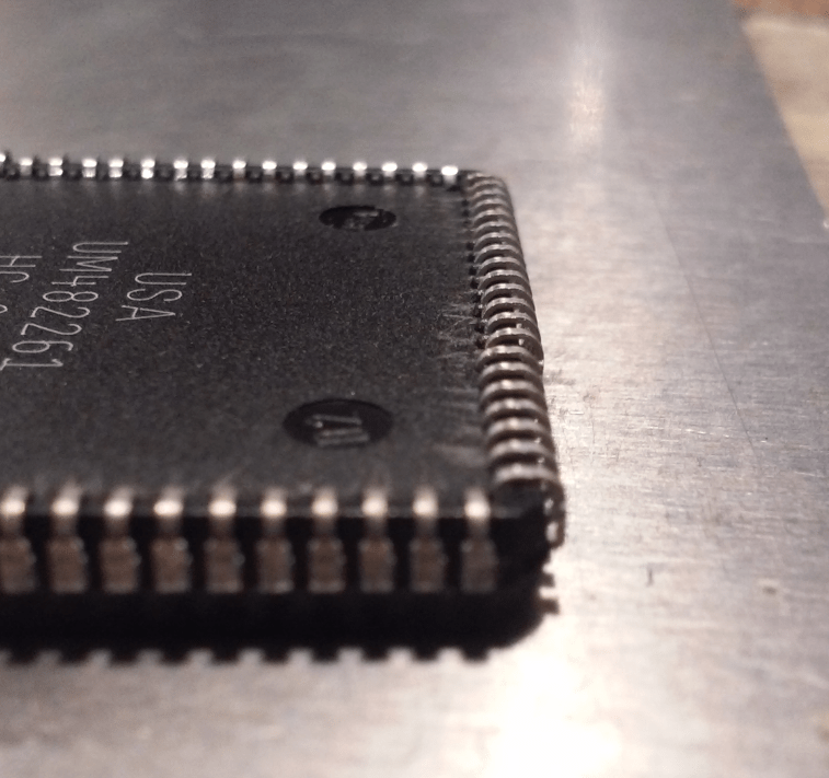
Later, I noticed that FAT AGNUS comes from various chip factories – in the Philippines and US.

The one from the Philippines is a bit easier to work with because of the small pockets and right underpins.
Although 30.7 mm was much better it still wasn’t enough to make proper contact with a socket and resulted in much fewer crashes but still, the system wasn’t stable enough.
After some work with a PLCC socket and decent cleaning, it finally stopped crashing.
Internal modulator – S-Video and Composite
Next on the list was a built-in modulator.
I’ve described it in one of my previous posts

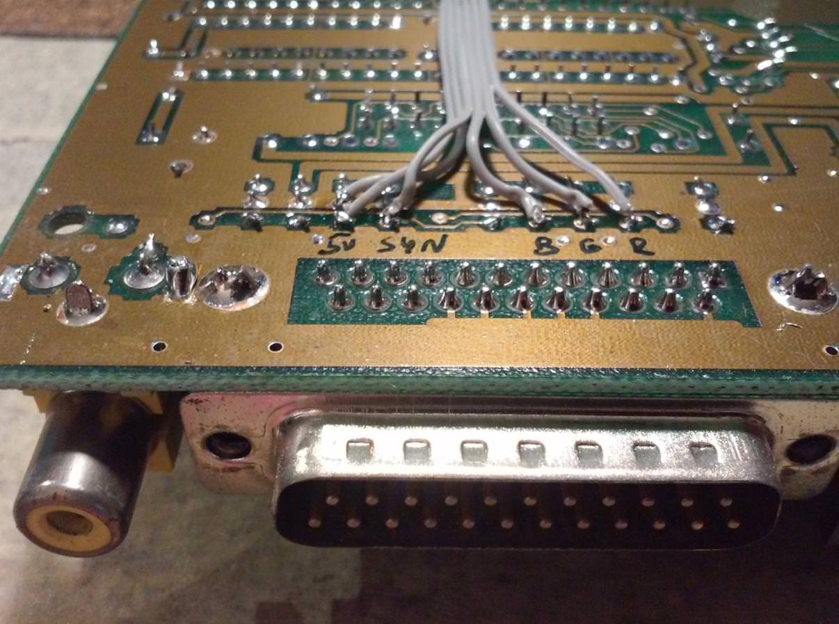
This module is available at retrohax.net online store and requires minimal soldering skills. Only six wires are needed – RED, GREEN, BLUE, SYNC, GND, +5V
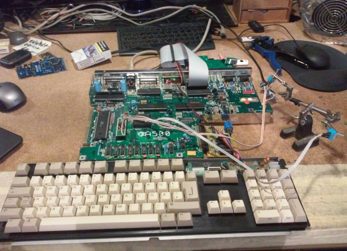
I had to run some tests on both (6A and 8A) motherboards to see if there are no unexpected pitfalls or surprises 😀
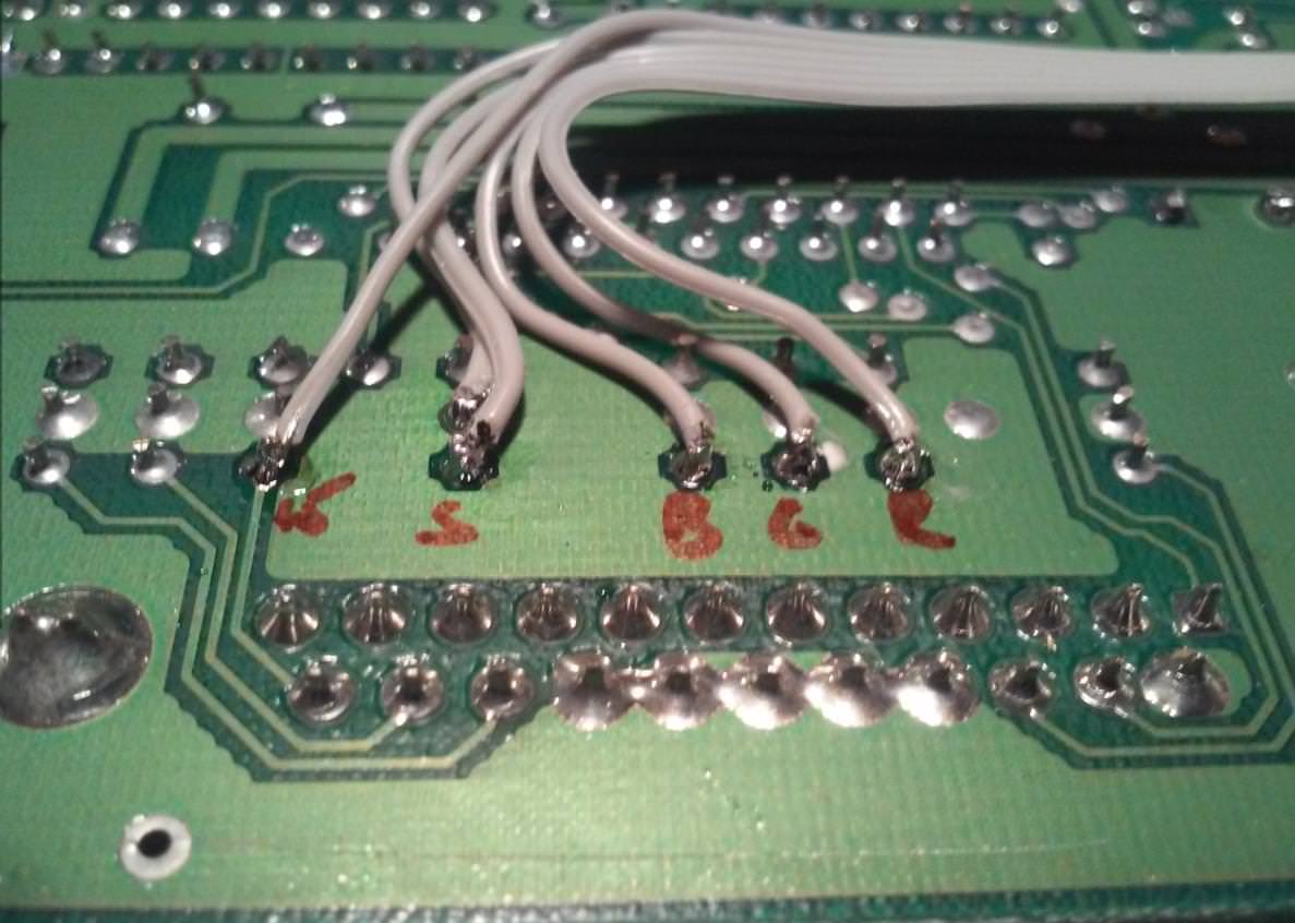
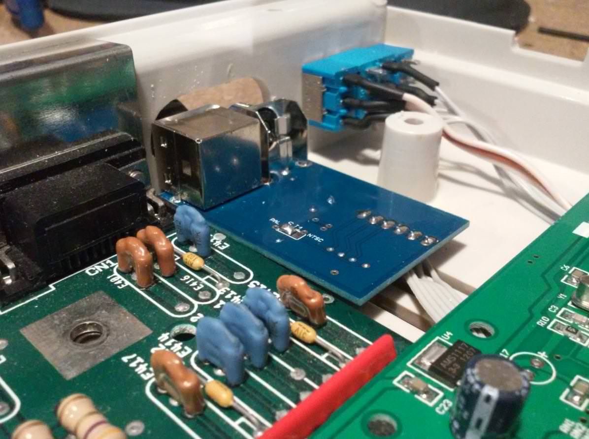
I’ve soldered signal and power supply wires to soldering pads near the RGB socket.
Here is how it looks on both mobo revisions.

Tadaaaa! It worked like a charm, plus the s-video is very crisp and the composite is way better than through the original A520 modulator.
Composite video

S-Video

Now it was just a matter of finding a nice spot to drill holes for sockets.
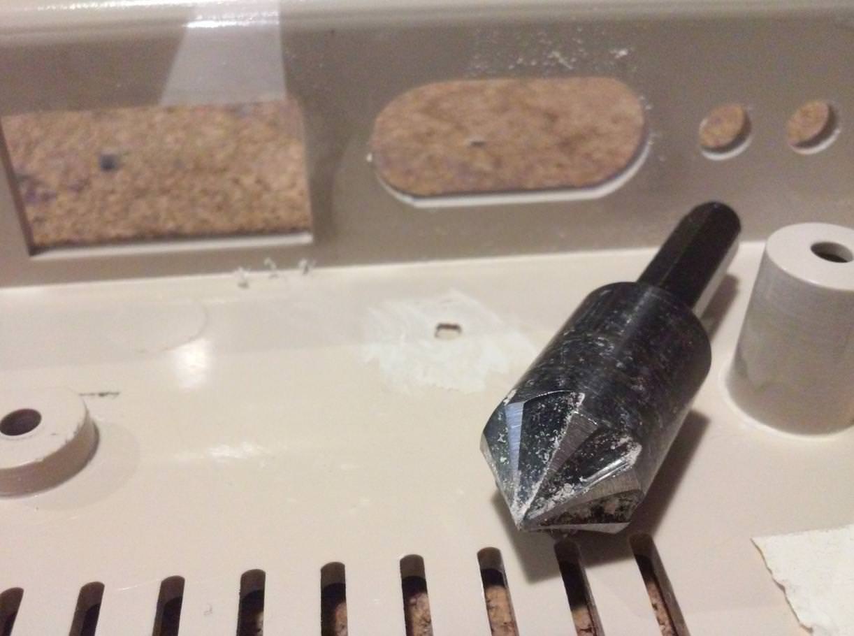
I must admit that drilling a plastic case with a 12mm drill is extremely tricky.
After a couple of failures, I ended up buying a tool that did the job nicely.
A bit of work with the file later …
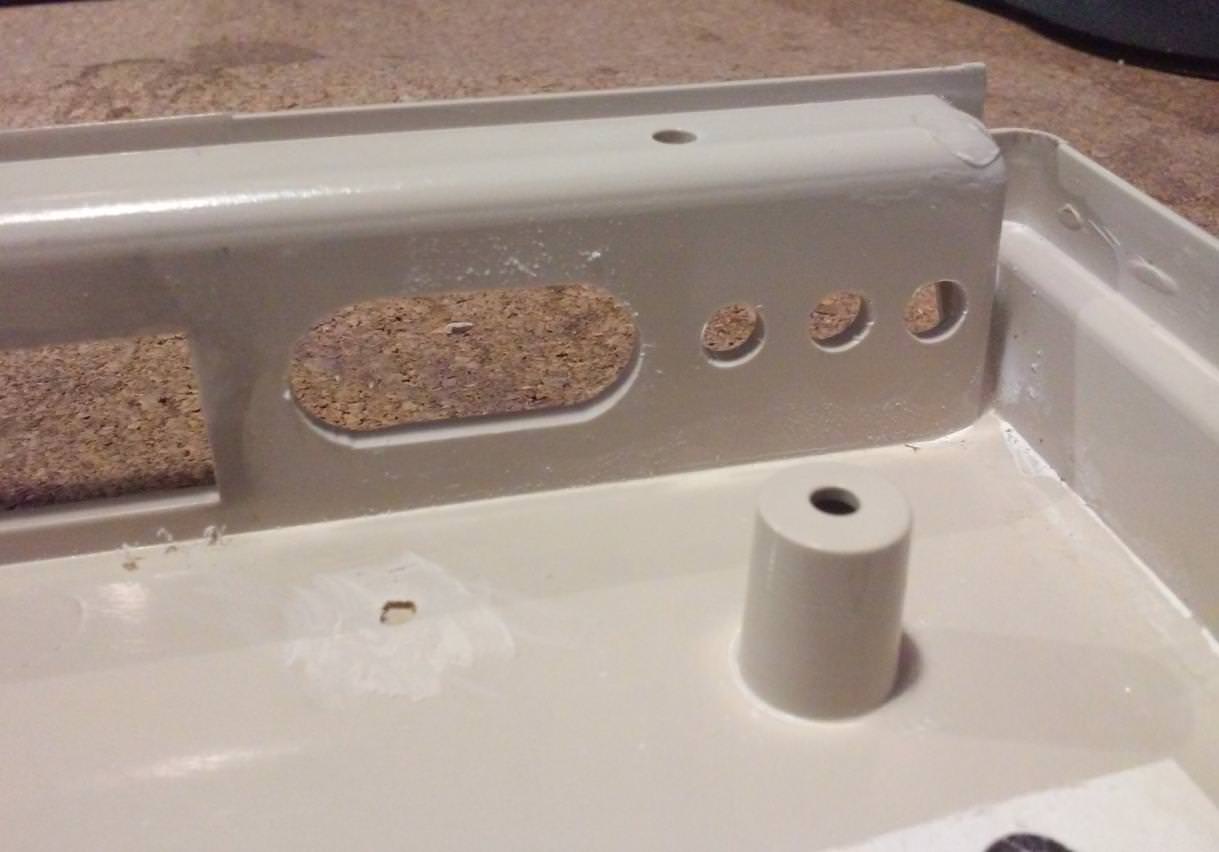
Below you can see an already mounted modulator.
Here is how it looks from the outside.

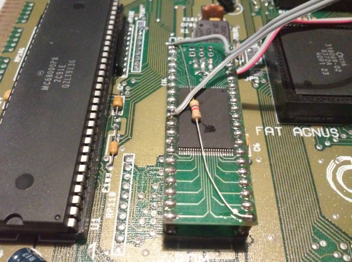
Dual KickStart – 1.3 / 3.1
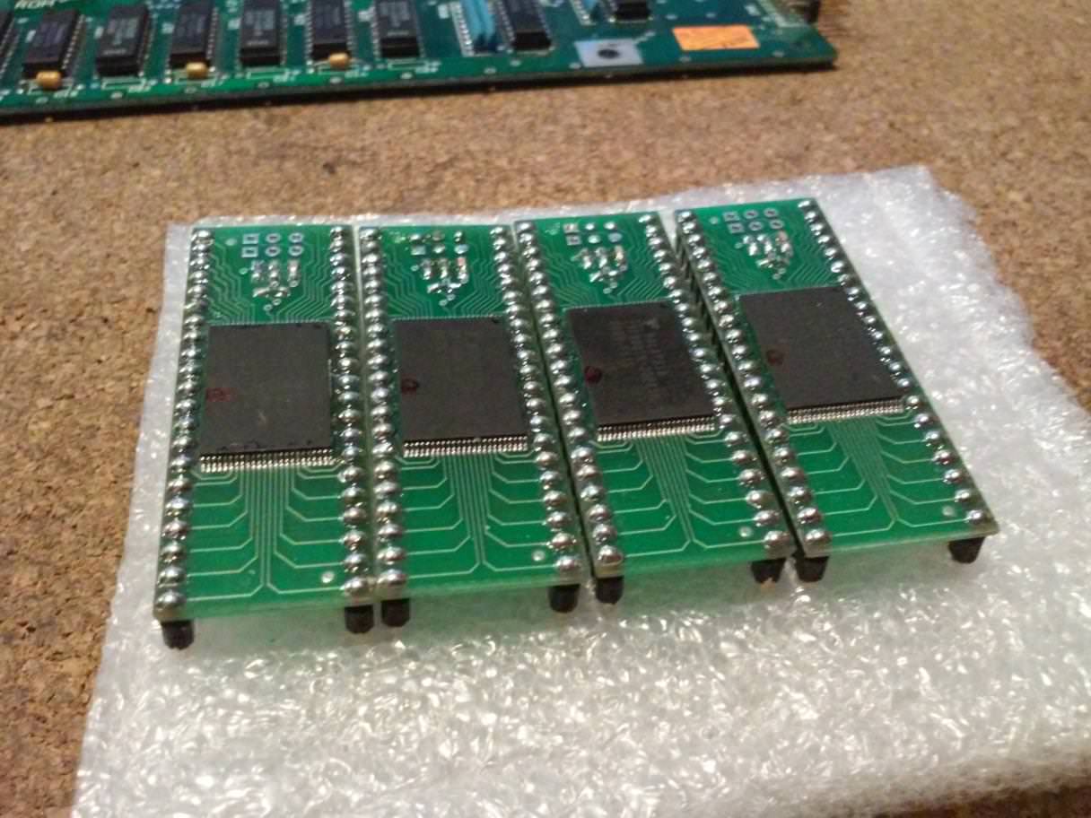
I also wanted to swap the original ROM for a bigger chip that would host two kickstarts, switchable of course.
That was achieved by burning two kickstarts on a 29F800 that was soldered to an adapter.
Chip programming was done using my super crappy Willem EZO programmer only because I already have an adapter for such a chip package. …. and yes, it takes ages to program it via Willem …
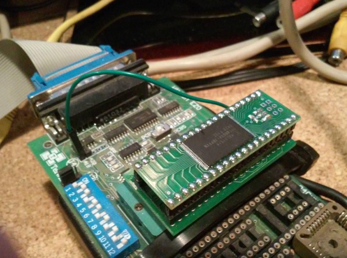

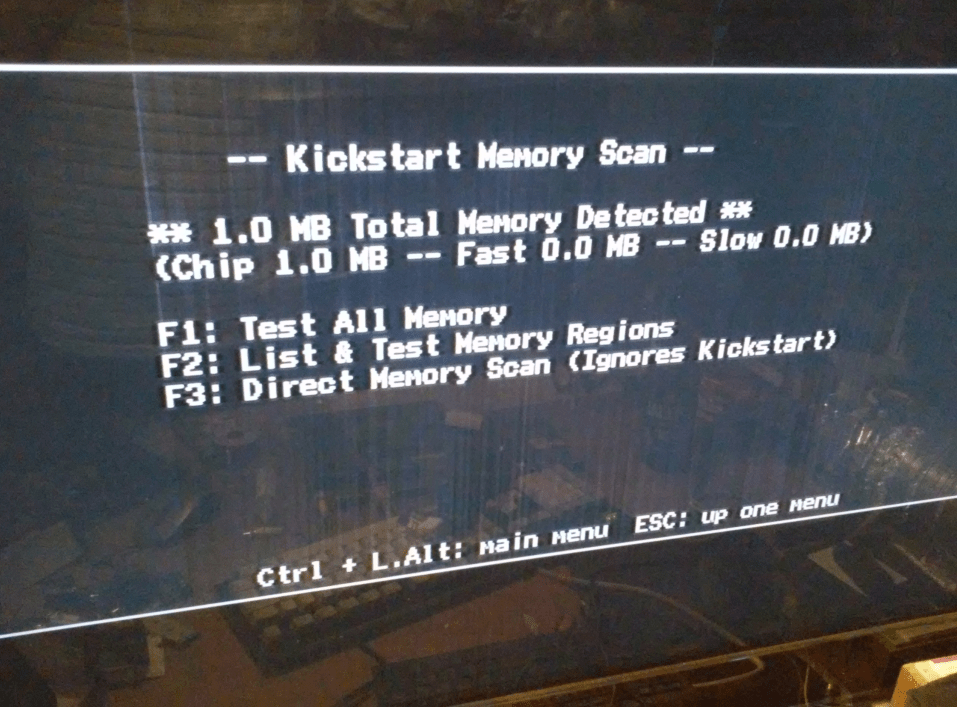
Running some final tests 🙂
GOTEK – USB Floppy emulator
I’ve bought several GOTEK drives to arm my A500s.
The idea here was to install a GOTEK USB floppy emulator along with an original Amiga floppy in case I wanted to run some software in an old-school way 😉 Of course, it had to be switchable. As usual, there were some tricks involved.
The first tricky bit was to flash a GOTEK with new firmware.
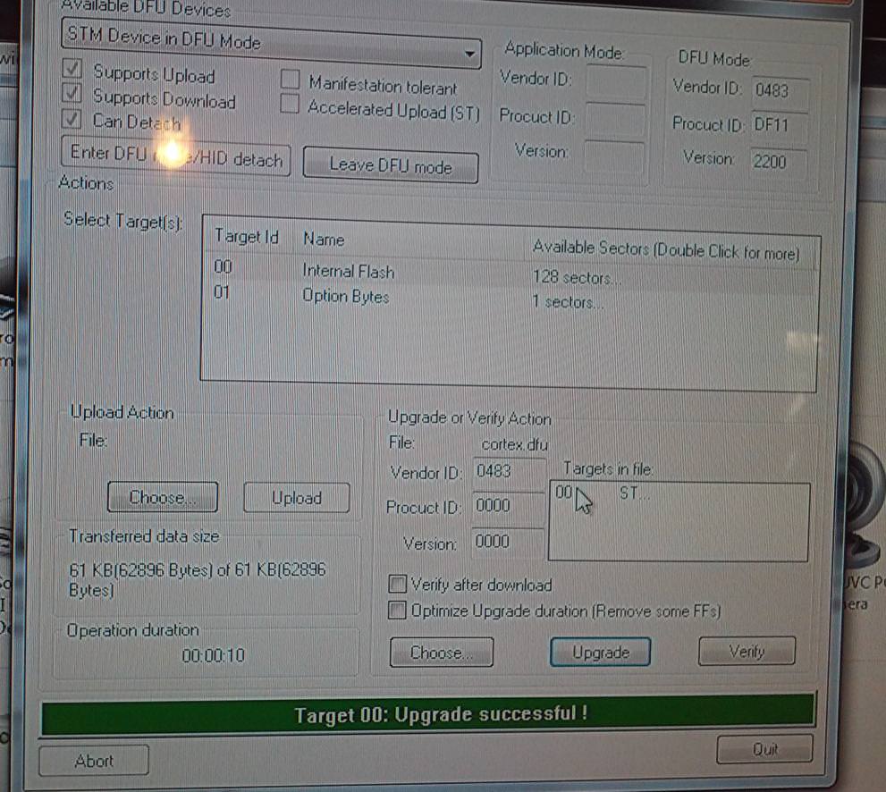
When I was playing with it, the only available open-source firmware was a Cortex. It is an excellent piece of software. However, not so long ago, FlashFloppy firmware was released which is another awesome alternative, plus it runs on Amiga, Atari ST, Amstrad, etc.
Unfortunately, I wasn’t able to program GOTEK through a usb2serial dongle (Yes, I’ve tried all three of ’em – pl2303, FTDI based, and cp2102) and even soldered directly to a chips RX/TX lines …. nothing worked. Fortunately, there is an alternative method of flashing ’em – through a USB with an STM32 in DFU mode.
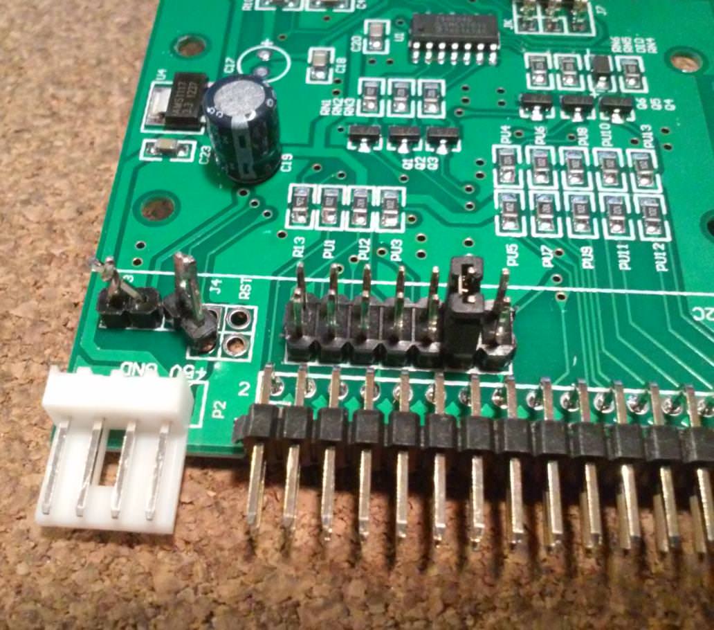
Jumpers setup for flashing in DFU mode.
Flashing in progress 🙂
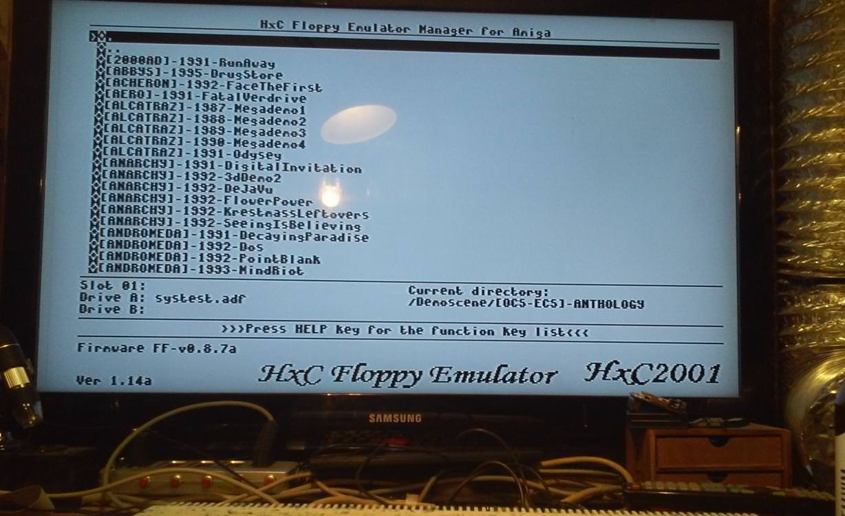
Below you can see pics of both firmware in action 🙂

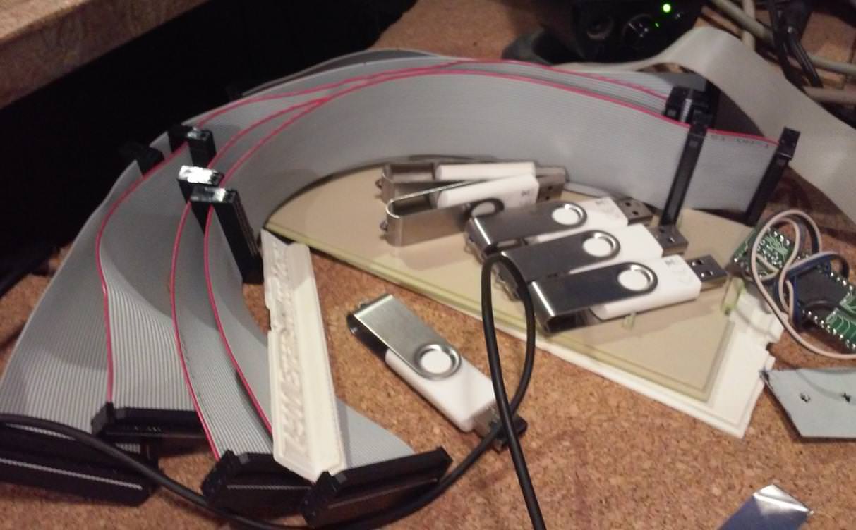
I prepared some 34PIN wires, and USB thumb drives, and I was ready to run some tests.

After successful tests, I could start working on the installation itself.
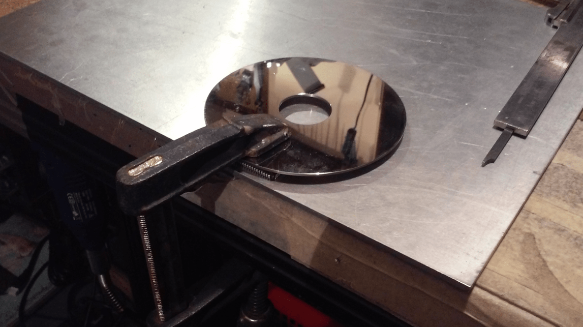
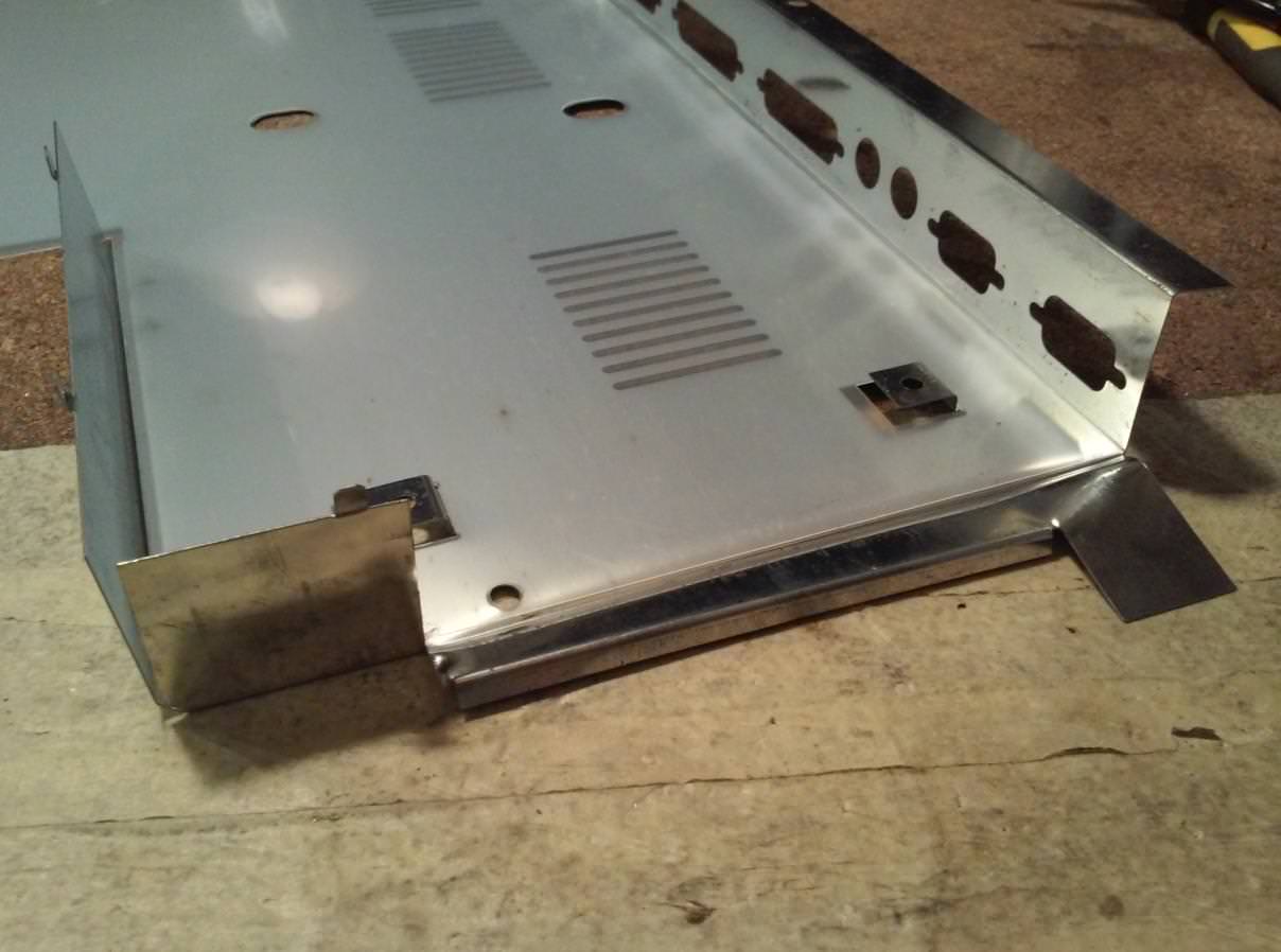
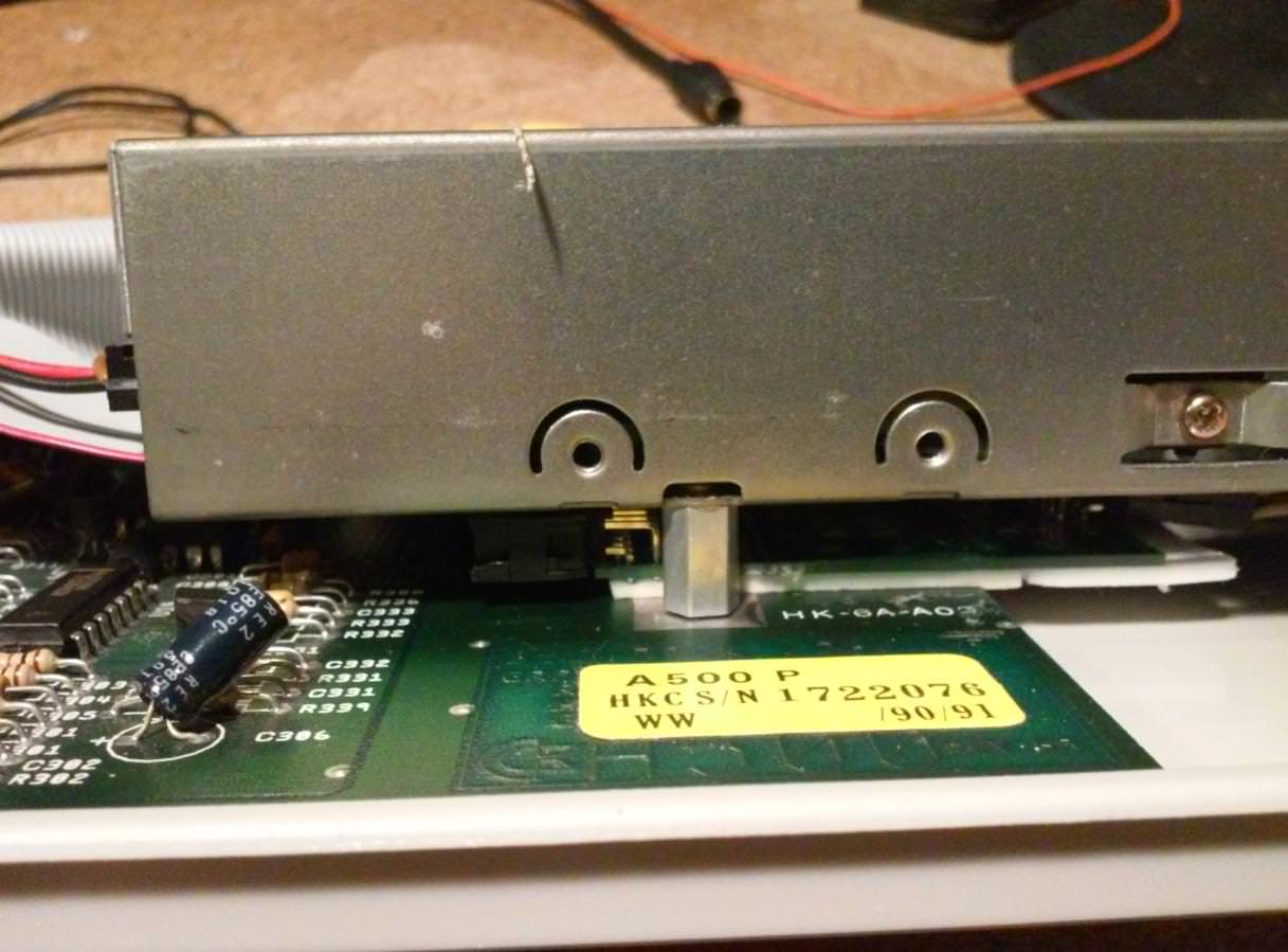
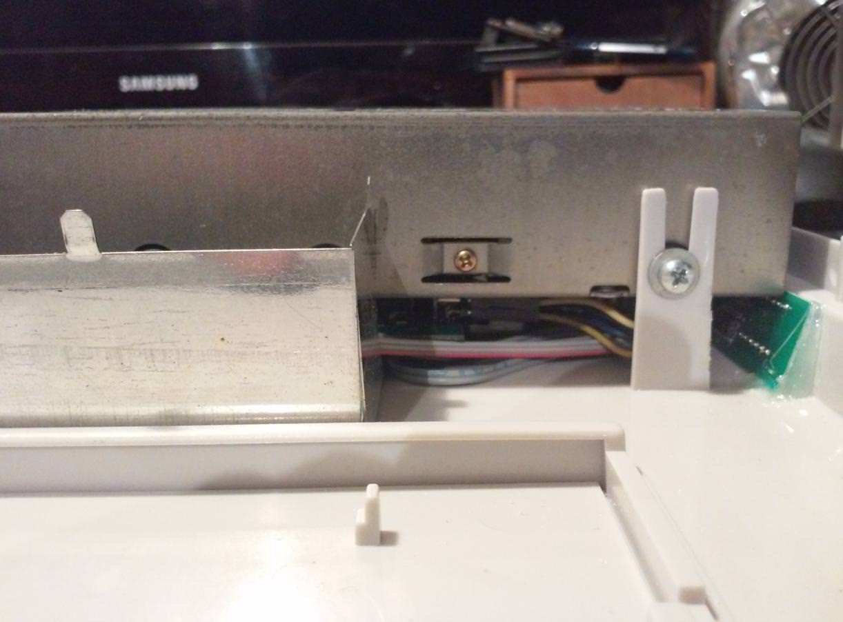
The first thing that needed a small mod was a bottom metal shielding.
The small part had to be removed from the one in the picture below
Troll mode on
Amiga is soooo awesome that even its shielding does demo effects lol 😀
0 CPU EFFECT below
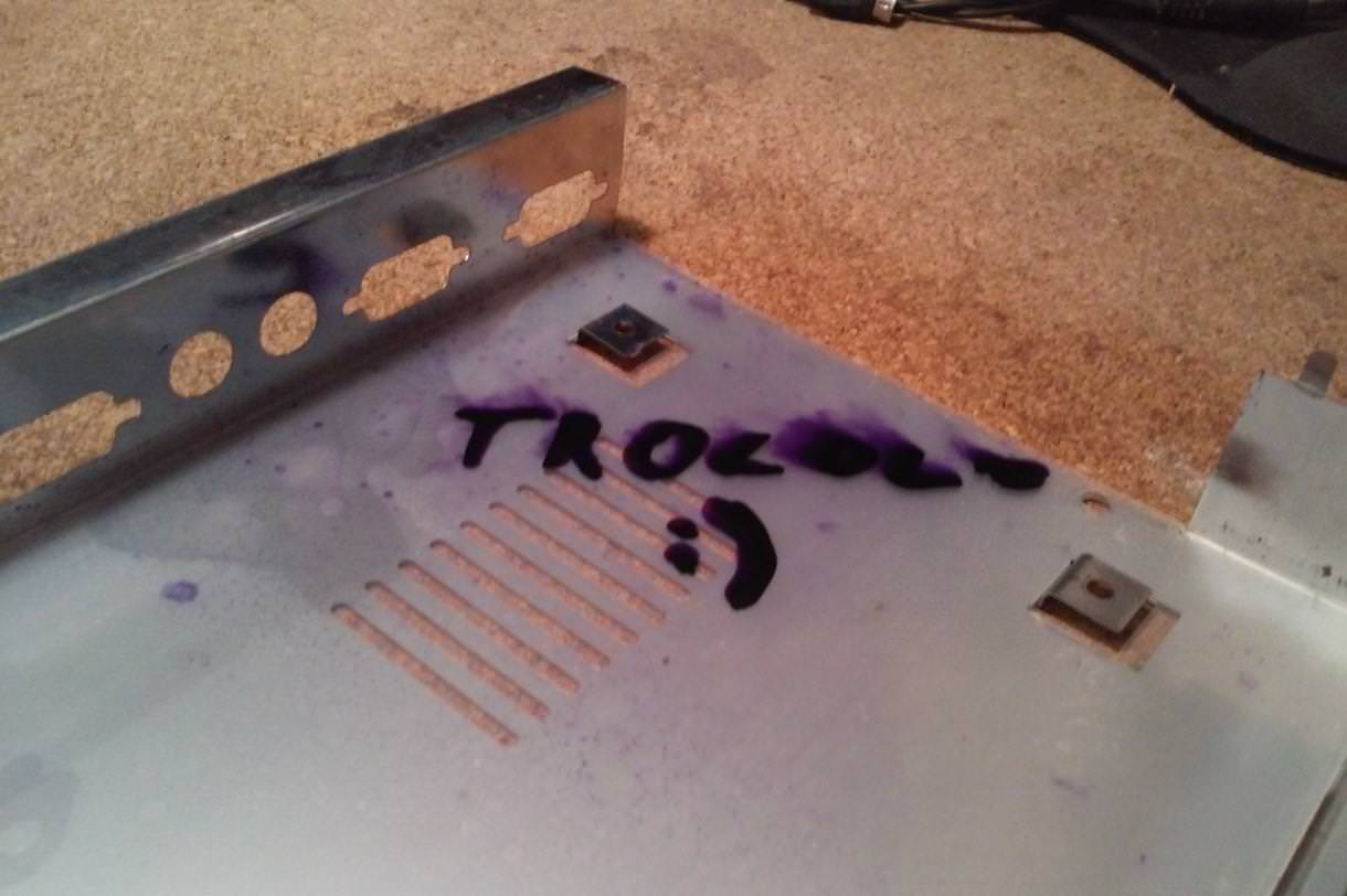
/Troll mode
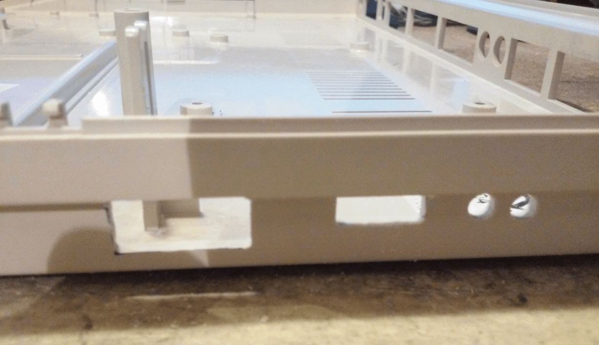
A case had to be prepared as well.
I decided that the best place for a bare GOTEK PCB will be under the original floppy drive. I had to cut holes for tact switches, USB sockets, and LCDs.
At first, holes were drilled and extended to the proper size with a file.
Here is how it looked.


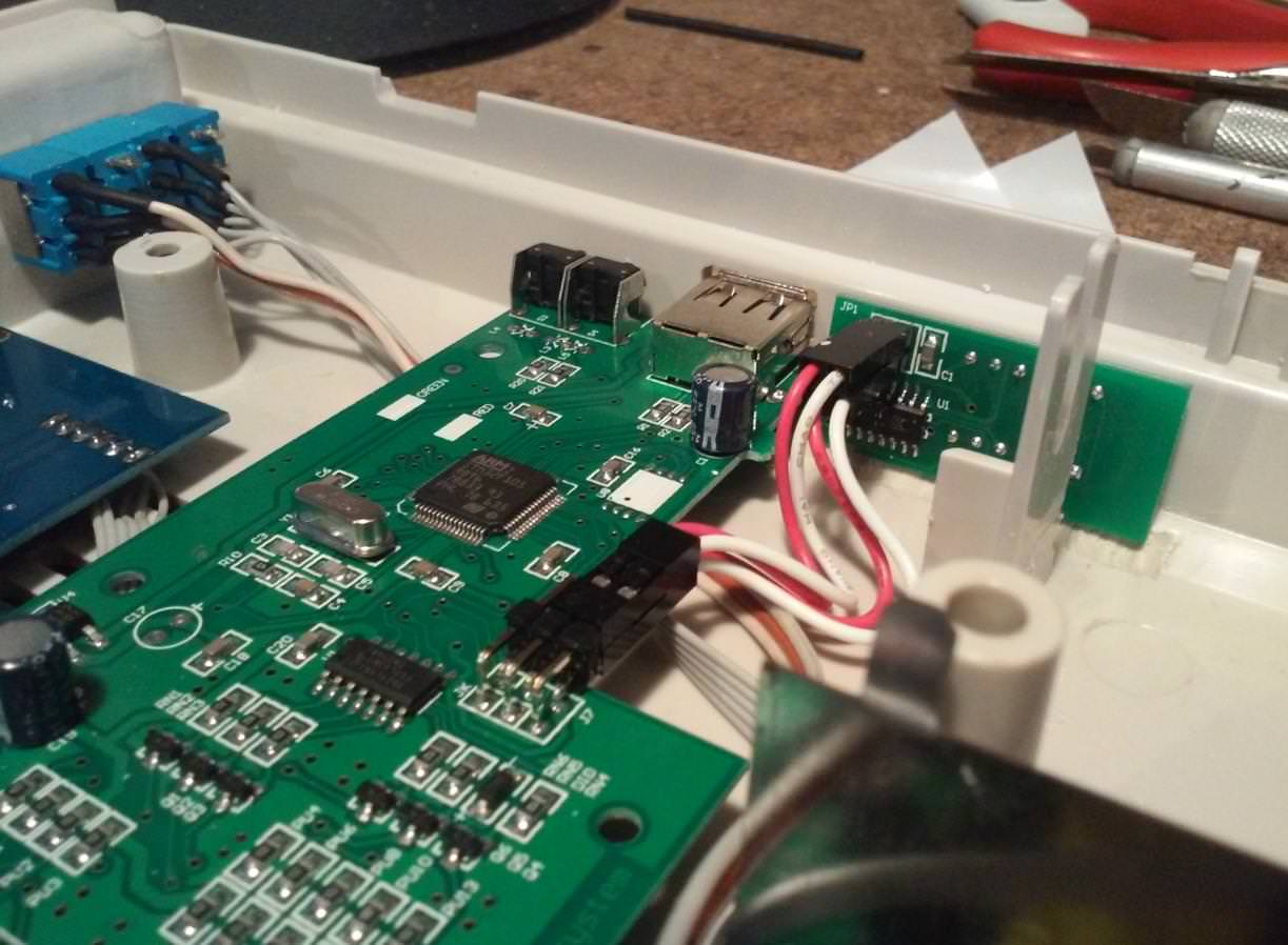
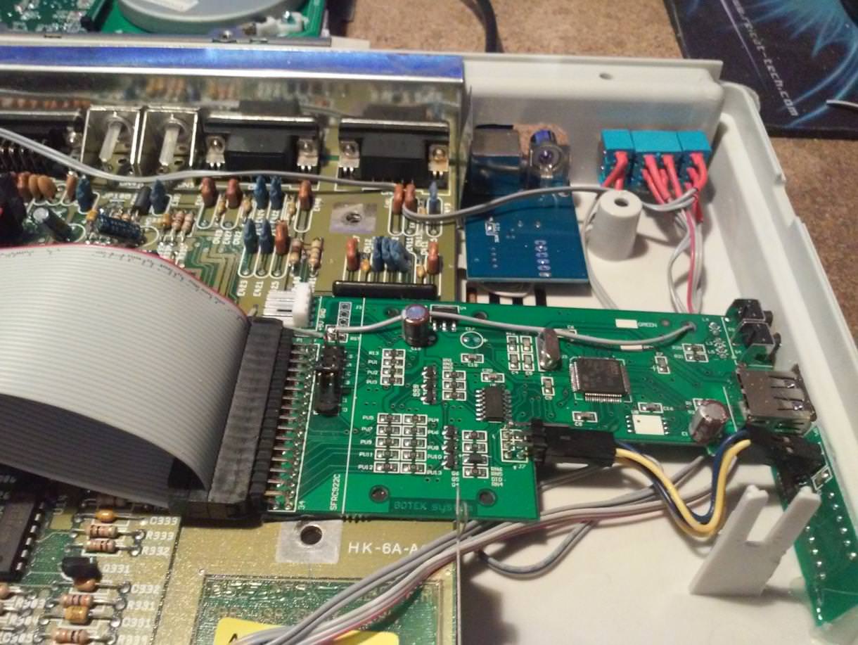
With a GOTEK in place.
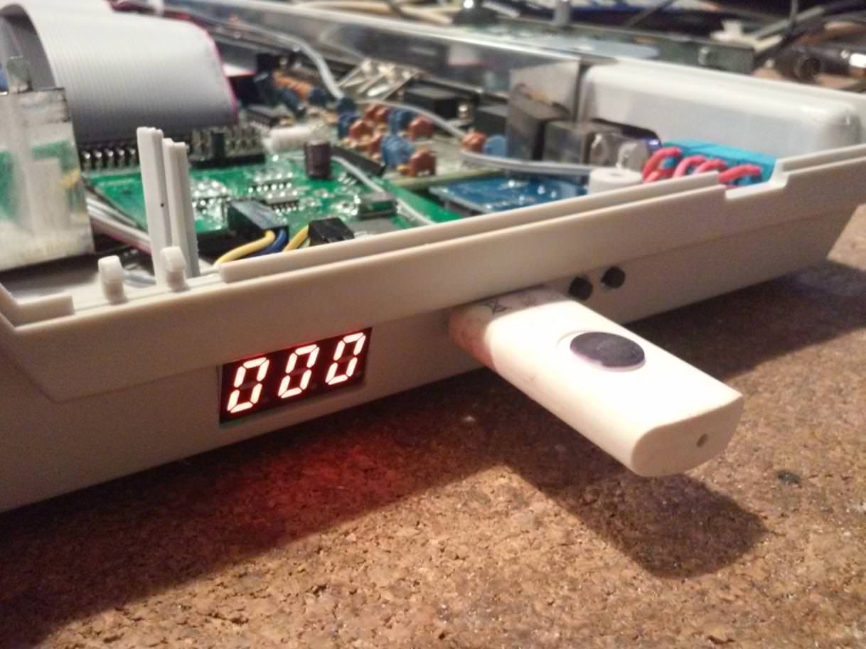
…and with a floppy drive on top of it.
Fits perfectly.

Assembled and ready for final testing 😉
That’s all for now. I am currently working (a shitload of projects would be the best description here) on hydrographic projects that will sort out problems with cases that are in very bad shape. Hopefully, I will be able to present ’em soon 😀
OUTRO
If you want to get retro gear or hardware modules, please visit our shop
New products are added every month.
Also, please support our work by spreading info about it.
Without your support, we simply cannot grow and we have a lot of new excellent retro hardware (and more) products to come 
I recently bought an A500 that has these exact mods, with the Gotek in the same position and the cutouts for it exactly the same. Maybe it’s one you modded. Anyway I’m having a lot of 8000 0004 guru errors. I’ll try cleaning Agnus’ socket and see if that helps
Maybe it was one of A500s that I worked on but who knows. If it has CHIPRAM switch then check if that guru error is appearing in both positions.
Hi
I have a Rev. 8A, but without clock and only with 512kB Chip.
Could you please describe how to use 512kB or 1MB to increase the Chip with the trapdoor Expansion?
JP2 was middle-up, JP7A middle-right, JP9 closed and JP3 ||.
If JP2 middle-down, JP7A open, JP9 open and JP3= nothing happens. My extra 1MB is not visible. I’ve checked it with my real 500+ with 1MB onboard. The Jumpers are like this.
Thank you.
Hi,
Recently, I’ve gathered all materials (pics and info) on this subject. I will be writing a detailed post on how to install 1MB chip in various mobos and 2MB chip in 8A.
I am writing from the top of my head so I might be wrong but IIRC what you need to do is to install 4 missing chips, then set JP2 to middle-down, JP3 || and JP7A open. This will give you 1MB chip ram. I might be wrong but I don’t recall chip ram upgrades thought trapdoor.
If you have a Rev. 8A with 1MB onboard and you put another 1MB inside of the trapdoor, it is also Chipram > 2MB. I’ve never changed any jumpers for this.
I want to keep the board like it is. No extra solder work, if I can avoid it. 1MB is enough and the rest can be inside of an Alfa Power for example.
Any news for a board like mine? I soldered U32 with open jumpers beneath it. JP7A and 9 are open, JP2 both possibilities checked, but I have only a green screen.
Hi, if You have a board rev8 with 512kb on board and You want to add a 512kb trapdoor ram, by default is set to 512 chip and 512 slow. But JP2 set ram map between chip and slow (default). Change blob on JP2 set trapdoor ram to map as chip. If trapdoor ram has a disable switch it must be set to disable OR JP7A must be open. This set Amiga to 1 MB chip (512 on board and 512 from trapdoor).
I don’t understand your Agnus measurements. From what I see in the first measurement pic it’s a bit more than 3 centimeters. And the later pictures do not show any difference (or I am blind). Where do you see 4.7mm? So can you please improve that description?
You are correct, there was a mistake in that description that probably appeared while I was moving from one blog engine to another. I’ve corrected it so it should be ok once caches are cleared.
Thanks, that’s better now. Still, maybe I don’t know how to correctly read the scale of your tool, but I do neither see 30,3mm nor 30,35mm nor 30,47mm in that pictures. All I see is 30,03mm maybe, but in all of them.
now it is all ok, that .47 was obviously wrong as a caliper shows up to 0.05 but all the rest is fine.
Hello its a verry cool mod, is there any posibillity that you could upload a schematic for the mod
Hi Kenneth, which exact mod do you have on mind ?
🙂all of Them, but espesially the gotek/floppy wiring, Its so neat👍
And is it posible that you have a template of the Case-holes-Mod🙂
Oh, I will have to prepare a separate post about it all someday but I cannot promise it will show up soon, I am afraid. I have quite a few posts to cover right now 😀
Its okay👍
Can you point the way to where i could find the switch you use
(The trible switch)
Sure, just search for “mts 203 switch” 🙂
Great🙂thanks
I really liked your mod and will try to do it myself. BTW, how did you make the drives switchable? Are they on at the same time? Is it possible to switch them between DF0 and DF1 with a flip of a switch? Thanks
To switch between DF0 and DF1 you would need a boot selector and one of the drives should be connected a bit differently. It is doable with a bit of tinkering but in this case I am only switching 5V rail between two drives. This is A500 so it is mainly for gaming 🙂
Hi can you help I’ve got an a500 rev6 board and I’m getting I suppose it’s a light green, and green light blinkin, I already tried to reseat angus 8372a several times, exchanged cia’s , reseated rom , and other chips. I felt some of the soldered rams were warm . this machine had an a501 installed. What I tried was to disable all the VCC supply going to all rams asto check if I still got a green screen. I disabled voltage to rams and still green screen. So what could be the issue? . Is there any jumper I need to move to enable the external a501?
Hi Paul. By green light, do you mean green screen after turning on A500?
If yes, then it indicated a CHIP RAM problem. Most often is a PLCC socket issue where FAT ANUS is. Reseating doesn’t always solve a problem. Remove Agnus and check if the pins of the socket are not corroded.
Another thing to check is RAM onboard – 4 chips. They can go warm while amiga is powered on but look for a chip that is really hot. If that doesn’t help RAM has to be swapped with new chips.
If it is about A501 there are usually two jumpers that can cause issues JP2 and JP7A. JP7A disables trapdoor expansion connector. Also, check for a jumper or switch on a A501 itself.
In general, there may be several causes. Let me know if above helped 🙂
Like to know if you have a template that I can use to drill the hole of the gotek in the same are that you did the mod.
Actually, I do, but I’ve made it out of a sheet of copper. However, you just gave me a cool idea. I can redo it in software and upload to blog 🙂
I don’t know when I’ll manage to do it though.